Build Your Own (Physical) 3D Models
Brief Overview On CNC Milling And The Coding Interface
A CNC machine needs only the geometric detail of the model, usually without textures. Textures can be further converted to reliefs, which can then be applied over the model's geometry. For my particular application and size I was able to get away with the simple 3D mesh I'd already created. Even though control of CNC machines can be done by computers with relatively slow processors, a speedy video card takes precedence over the visualization/creation of a 3D model and proofing of any animation and effects.
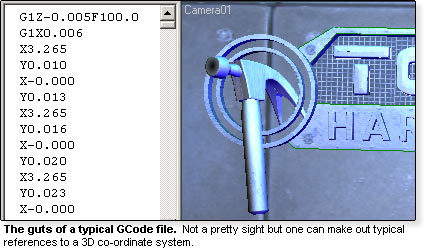
CNC mills, mine included, understand a complex set of mathematical formulas commonly referred to as GCode. This data is interpreted by the machine as a sequence of moves relating to X, Y and Z axes and combinations thereof. While opening a file appears to display a gibberish of numbers and text, the machine interprets it as a series of lines and curves that comprise the physical model.
CNC technology is pretty simple, but effective. Basically, X, Y and Z axes are fed along an I/O channel to a set off stepper motors, which interpolate the amount of spin needed along the given axis to represent distance. The first step in creating the physical model is to export the information from 3D Studio Max into a program that can write GCode for a particular machine. GCode is somewhat universal, but small changes in its structural syntax can adversely affect movements with disastrous results. One must be careful when porting GCode not written specifically to one's machine, as this can cause the bit to perform unintended movement. A CNC operator doesn't want a sparking dynamo replete with a bit ready to plunge into the machine bed or destroy an expensive piece of stock due to script malfunction.
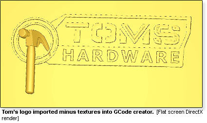
3D Studio Max has always had the strength of being able to convert from Autodesk's AutoCad into a variety of file formats. For the program I'm using the export determination is the Stereo Lithograph or .STL format. This will allow for easy import and manipulation using the multiple toolsets available in the GCode creator.
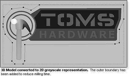
Once the model has been imported, it is advisable to convert it into a 2D grayscale representation to work with tool boundaries more efficiently. Tracing a contour line around the outer boundary of the model will allow the tool bit to move only along the interior of this spline in an XYZ direction. This saves a great deal of time as the bit does not have to trace the entire boundary of the model as framed by its maximum limit, represented by the outer rectangle in the picture below.
Get Tom's Hardware's best news and in-depth reviews, straight to your inbox.
Current page: Brief Overview On CNC Milling And The Coding Interface
Prev Page 3D Modeling Is Not Just For Video Games! Next Page The Roughing Pass

