How To Build A $500 Gaming PC
Our $500 Best PC Build provides excellent entry-level 1080p gaming performance at bottom-of-the-barrel pricing. The Intel Core i3-7100 is a speedy chip for a budget build, and the lack of dual-channel memory is a trade-off with some risk in gaming performance. That 8GB is sufficient for some top-end games, but the single memory module has lower total memory bandwidth than a dual-channel kit, and memory-intensive tasks are stunted because of it.
The Asus RX 460 graphics card performs well for the price, pushing playable framerates in some hard-hitting game titles at 1080p on high settings (see GTAV and Bioshock Infinite). However, we’d recommend pulling back on the anti-aliasing and other higher detail settings to get it to play above 60 FPS for some of the more demanding games. The 450W SFX PSU won't sweat with the low-power CPU and GPU, and there’s adequate storage capacity with the 750GB 7,200RPM 2.5” HDD. However, load times can be painfully slow.
The main attraction of this build is the Fractal Node 202 case, which impresses us with its versatility. Although the case restricts you to only two 2.5" drives, you could easily create an attractive and accessible SFF living room gaming machine using it as a starting point, with space for full-size GPUs, and easy-to-remove cages and frames to make assembling a PC within a restricted chassis much easier. It’s not the flashiest case, but it has a sleek look.
Specifications
| "I can ITX anything you can ATX" by Why_Wolf | |
|---|---|
| Case | Node 202 |
| CPU | Core i3-7100 |
| Graphics | RX 460 |
| Memory | Crucial CT8G4DFS8213 8GB DDR4 RAM |
| Motherboard | ASRock H110M-ITX/ac |
| Storage | WD Blue 750GB Mobile HDD |
Now, let’s assemble the $500 Best PC Build.
The Case
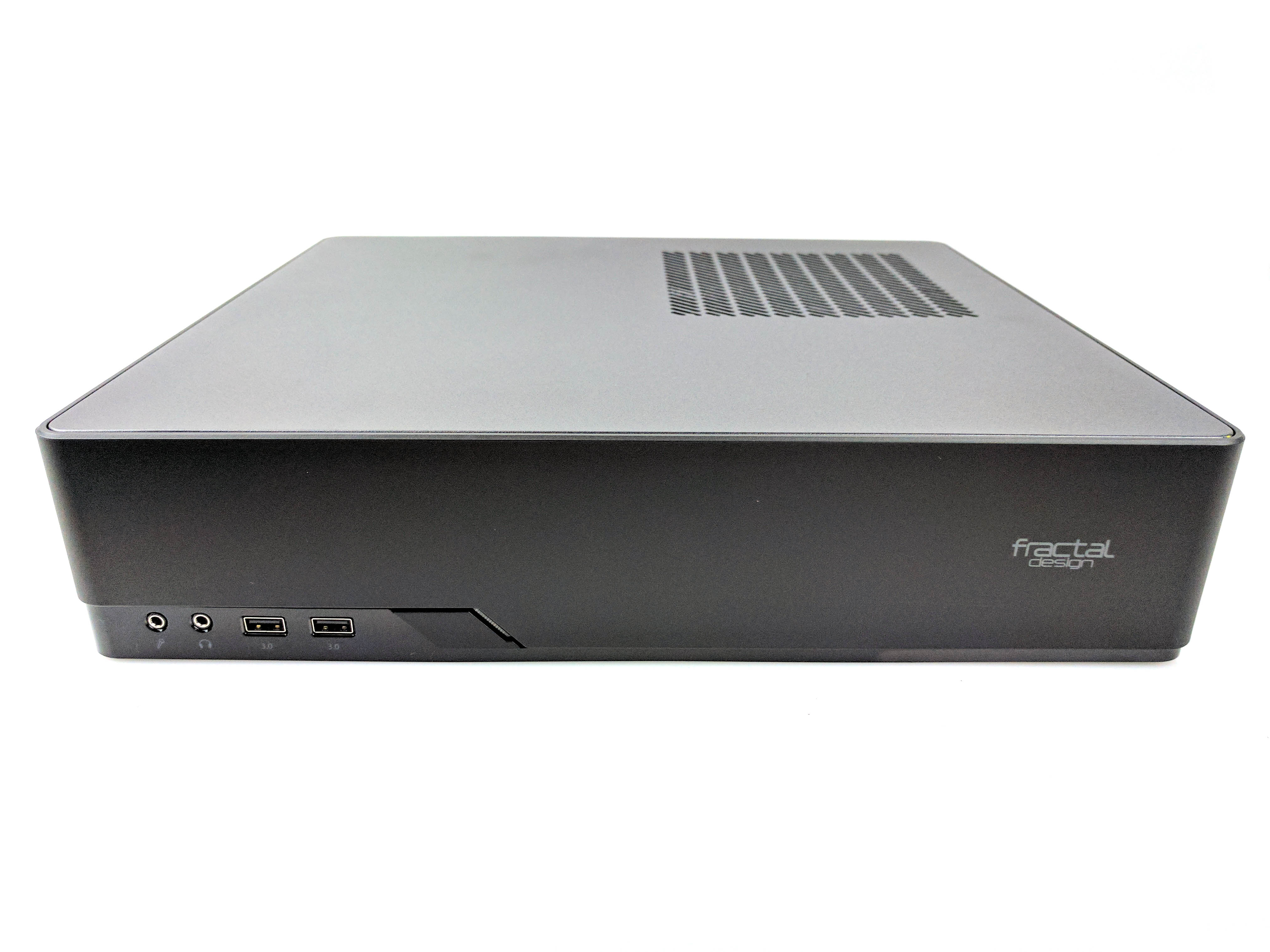
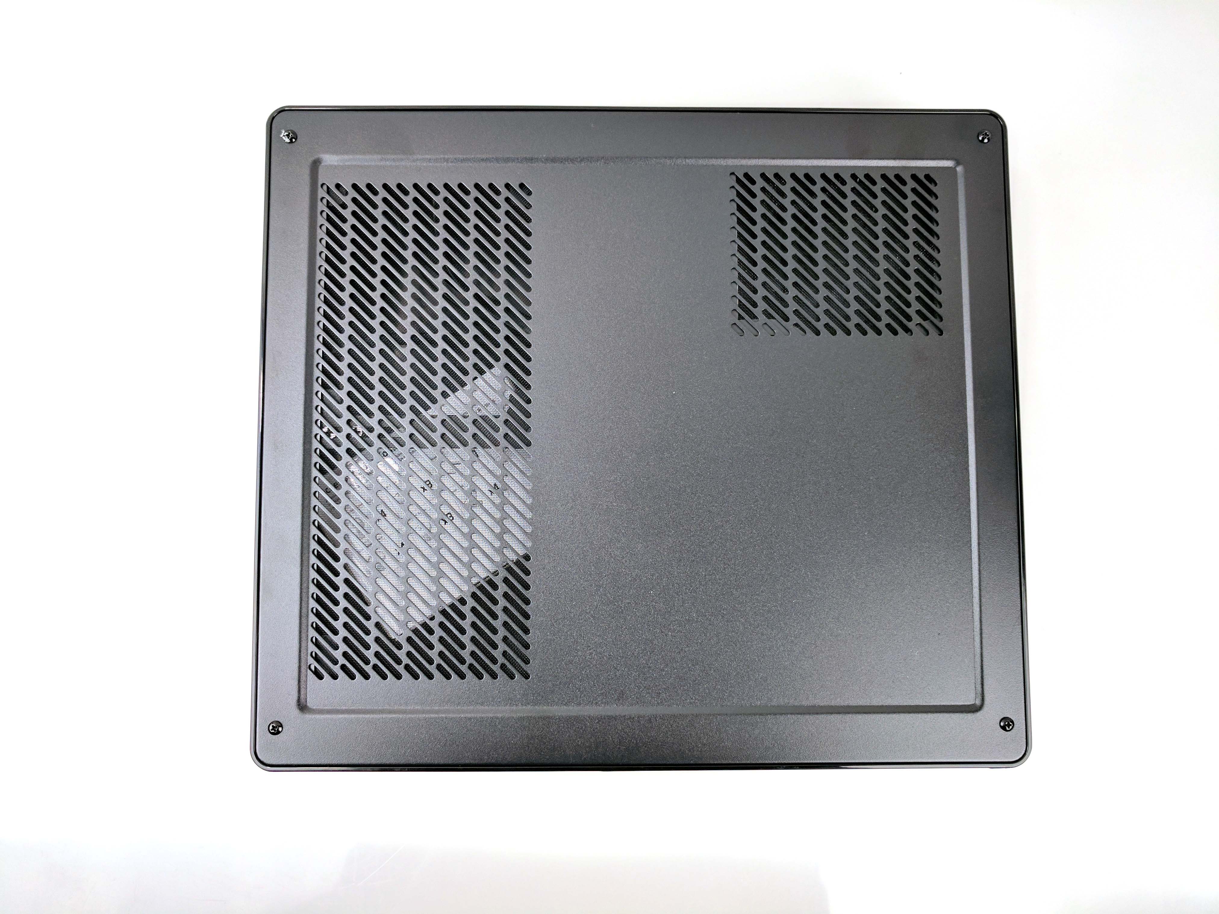
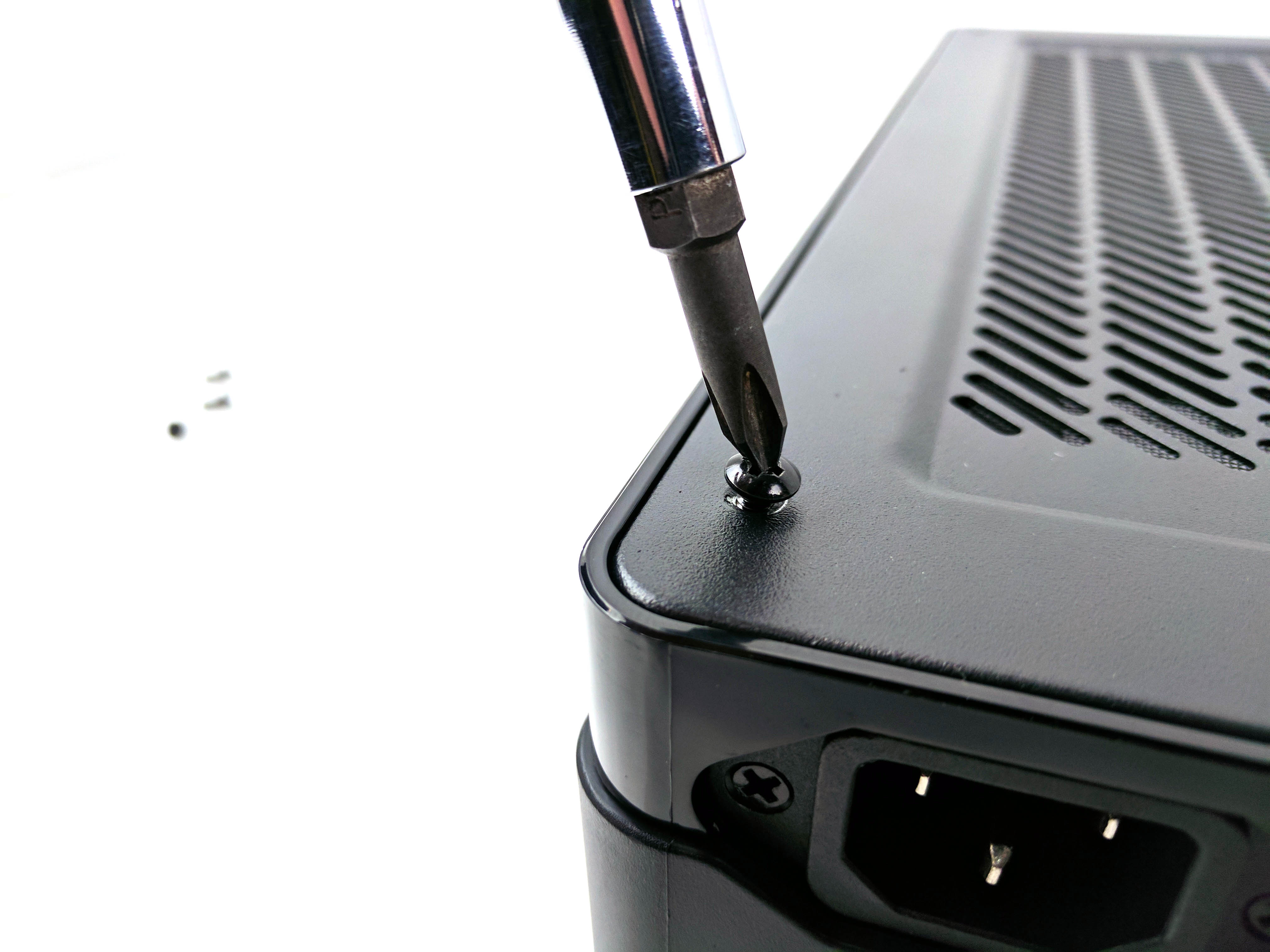
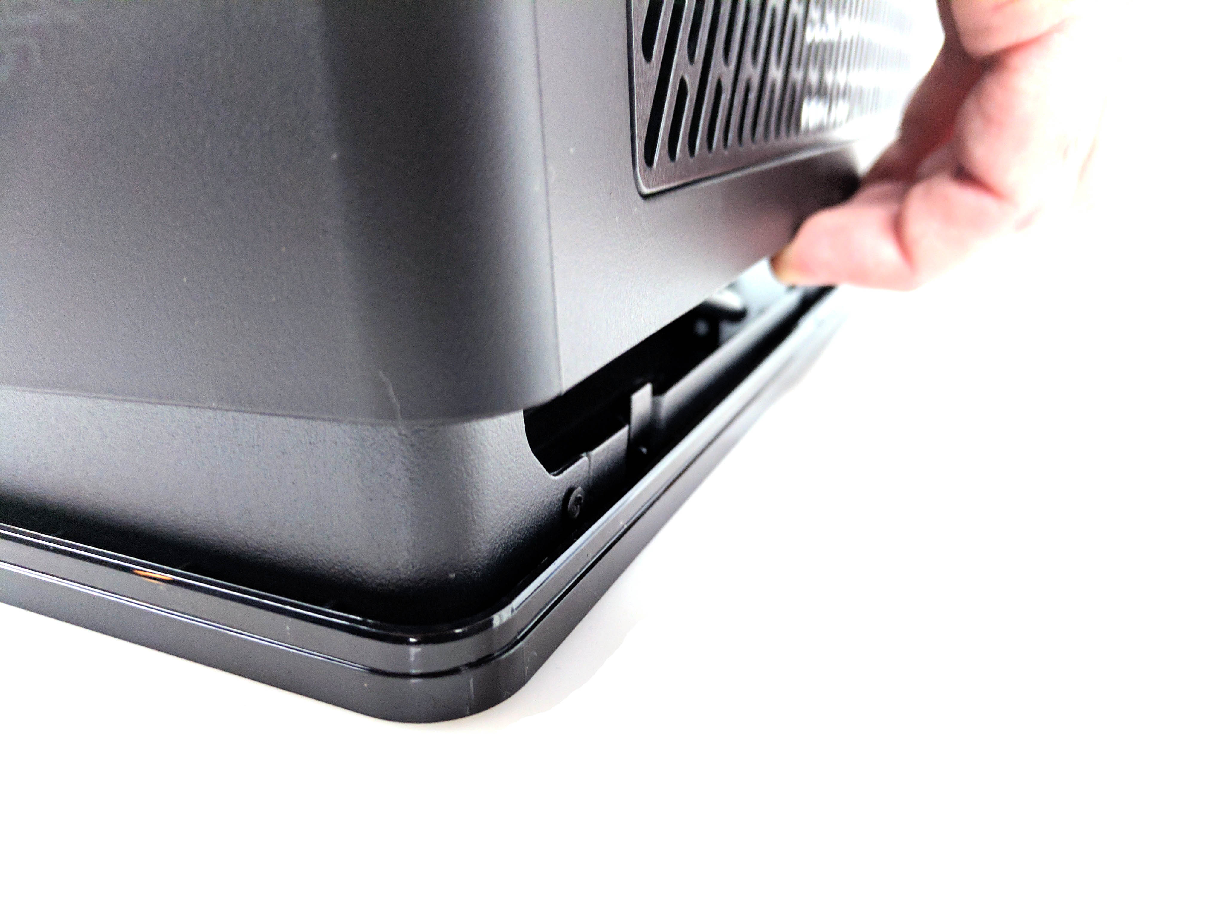
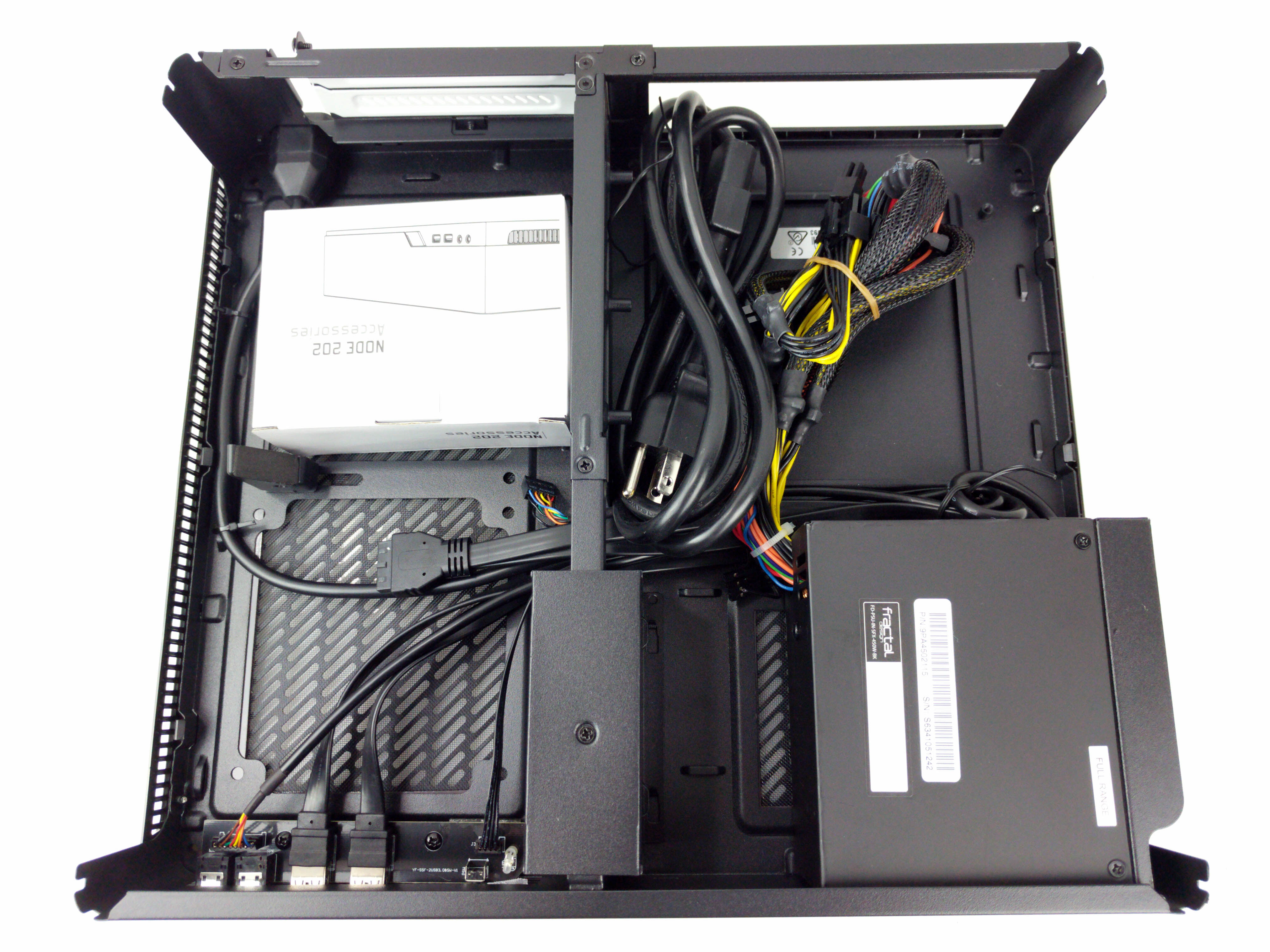
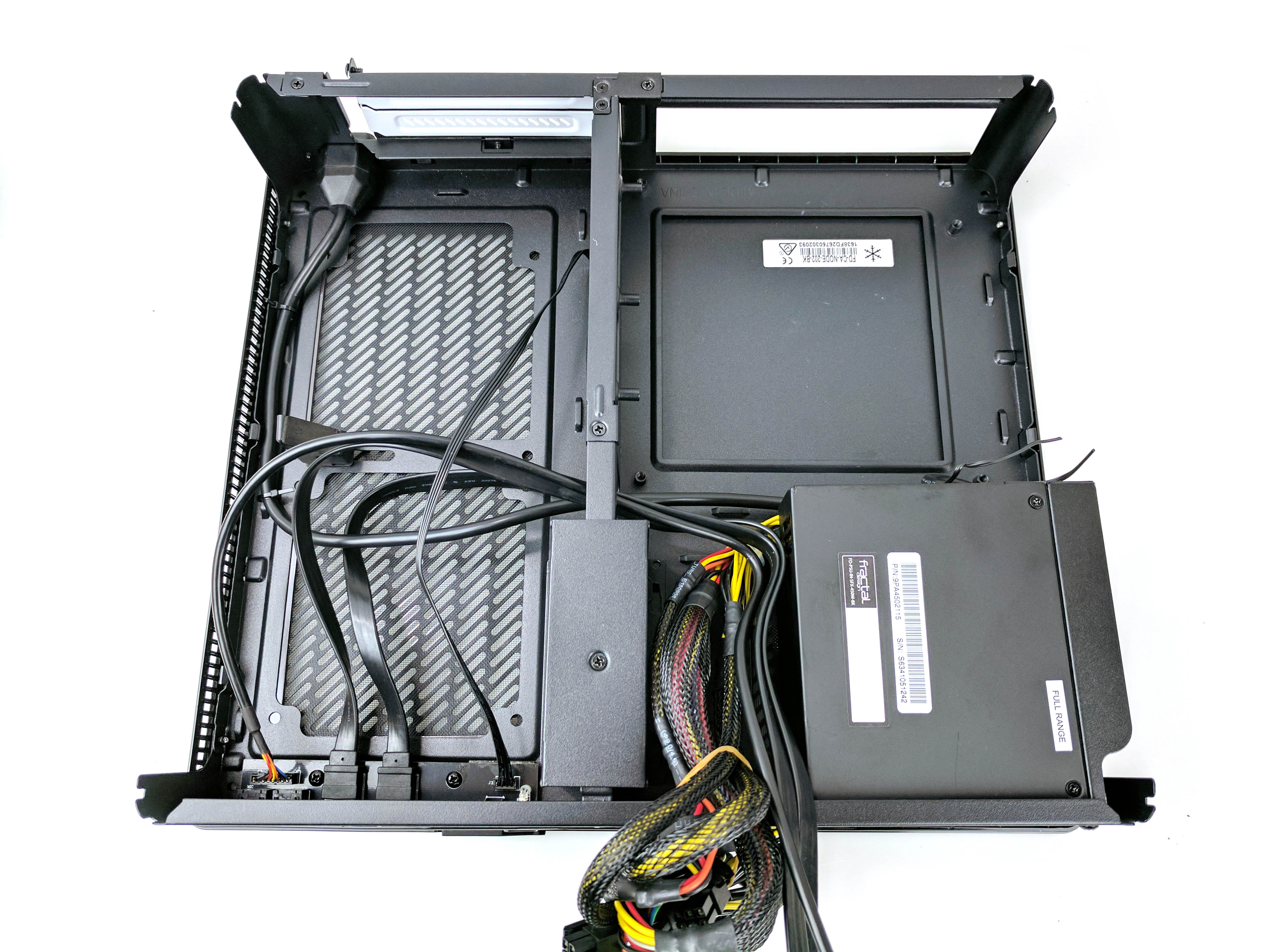
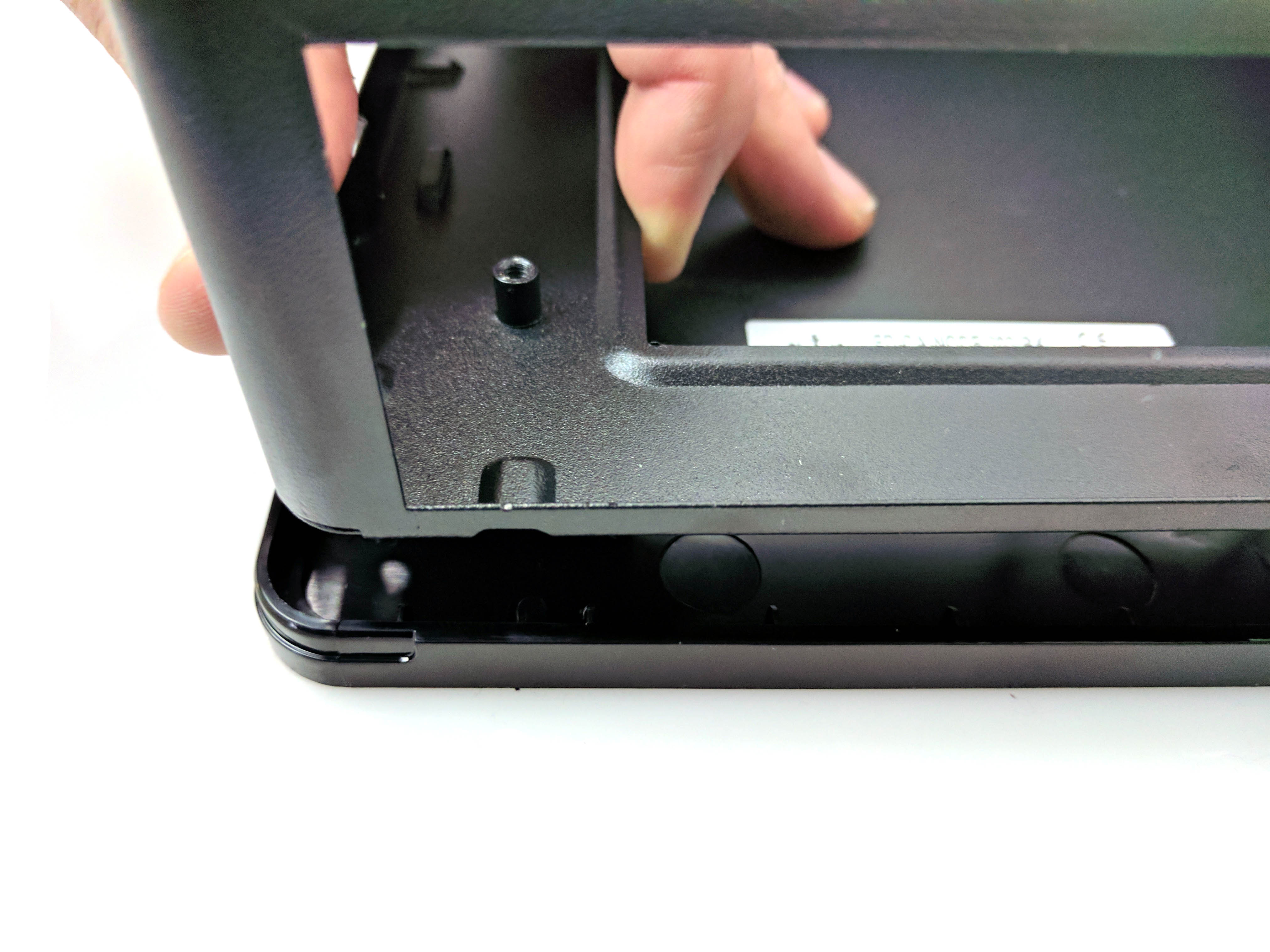
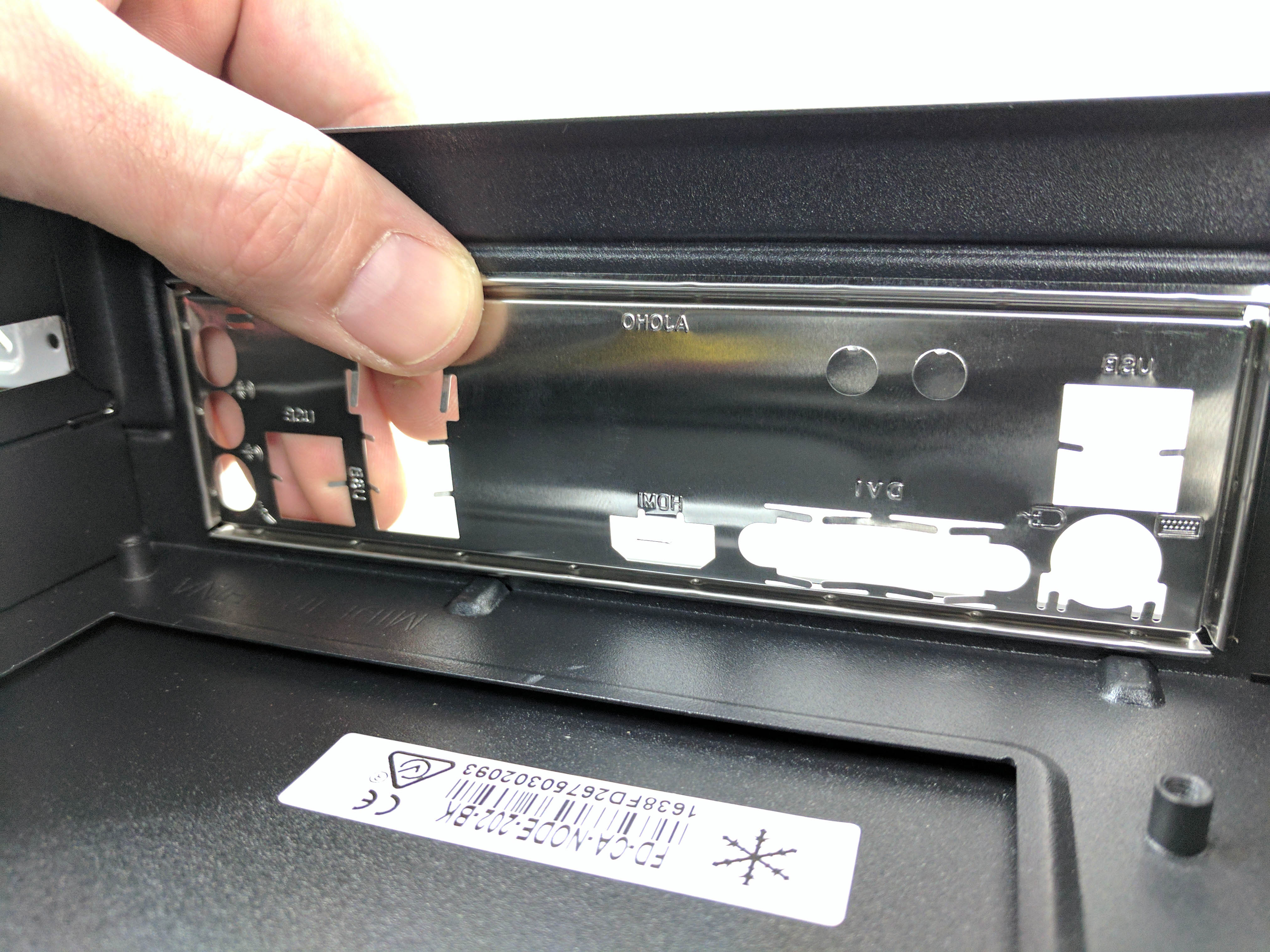
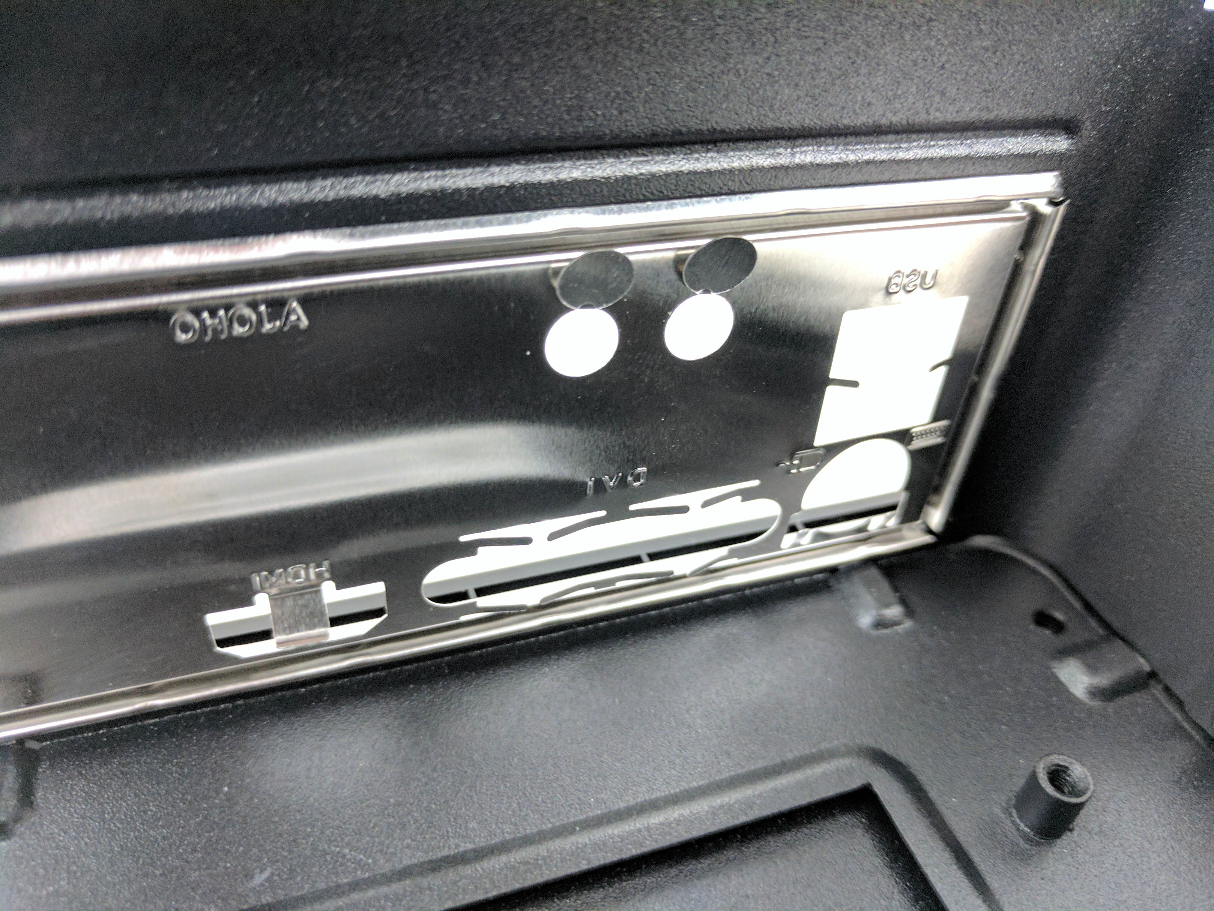
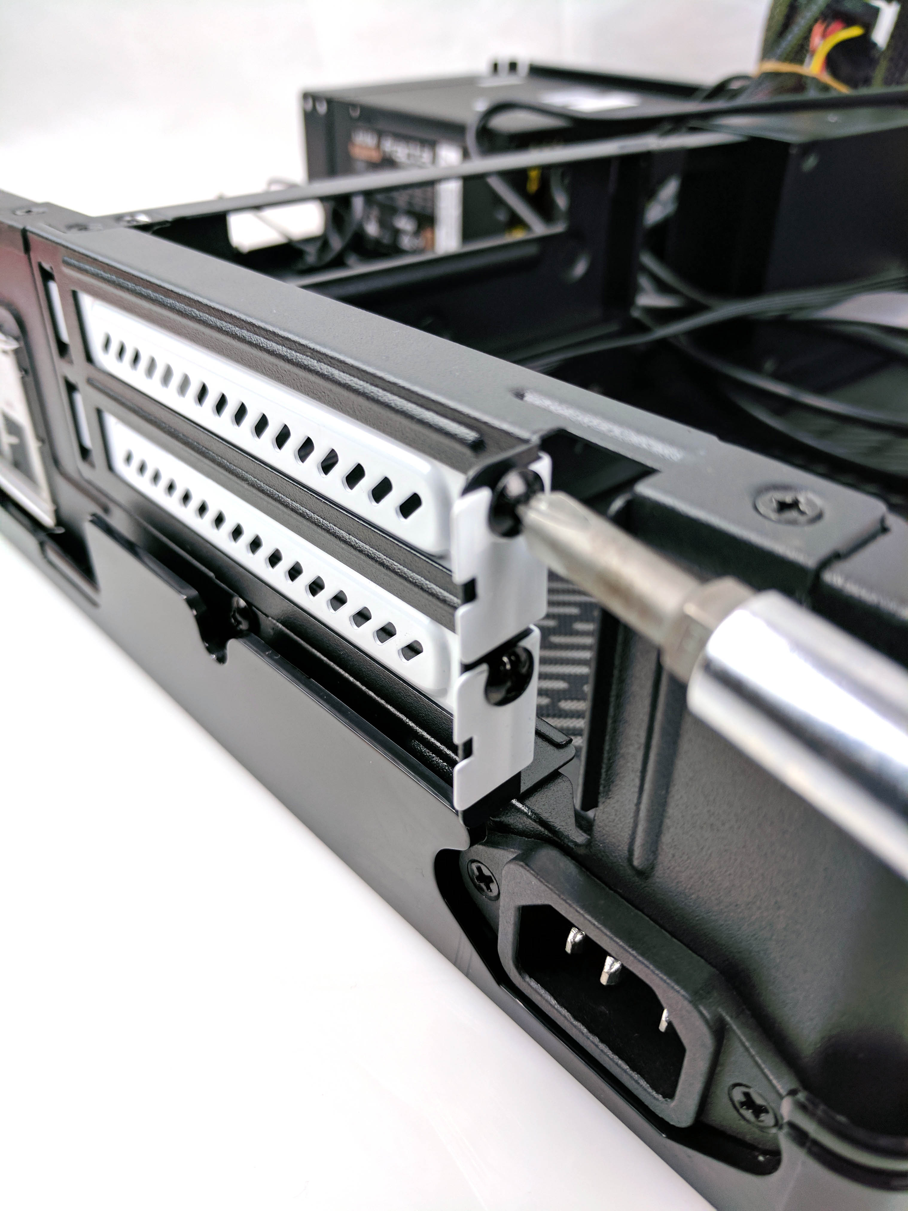
The Fractal Node 202 case is the star of the show, and it’s an ideal choice for a small form factor (SFF) system. It supports mini-ITX motherboards and full-sized graphics cards. Start by removing the case from the box and setting it on your workspace.
Flip the case so that the bottom panel (laying flat) is face up and remove the four screws (one in each corner), as you see in the third slide above. Flip the chassis again and lift up on the cover to remove it.
Remove the power cable and hardware box from inside the chassis. This particular Fractal Node 202 comes with a 450W power supply. Untie the bundle of cables and pull them back so that you have free access to the motherboard tray.
Get Tom's Hardware's best news and in-depth reviews, straight to your inbox.
You can also remove the bottom tray if you want, but you really won’t need to get to the case’s underside until one of the last steps, so we've left it attached. However, it’s not a bad idea to get it started by applying pressure to the panel from the motherboard tray and gently pulling back on the tabs of the cover (see the sixth and seventh slide in the album above).
Grab your motherboard box and locate the motherboard rear I/O panel. Install the backplate to the case and punch out the two perforated holes above the DVI slot to make room for the WiFi antenna threads (slides 8-10). Remove the PCIe plates on the case’s back panel.
The Motherboard & CPU
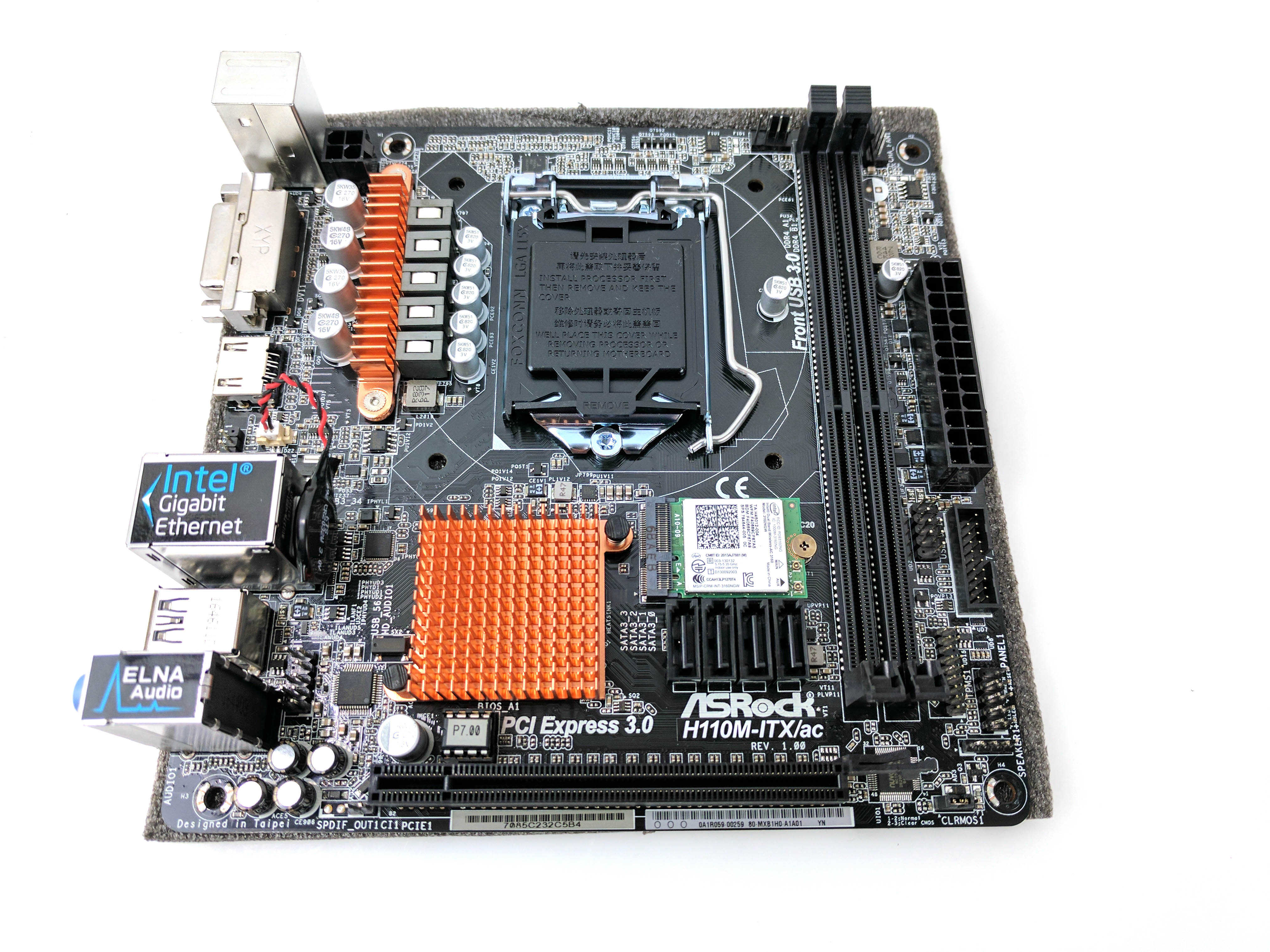
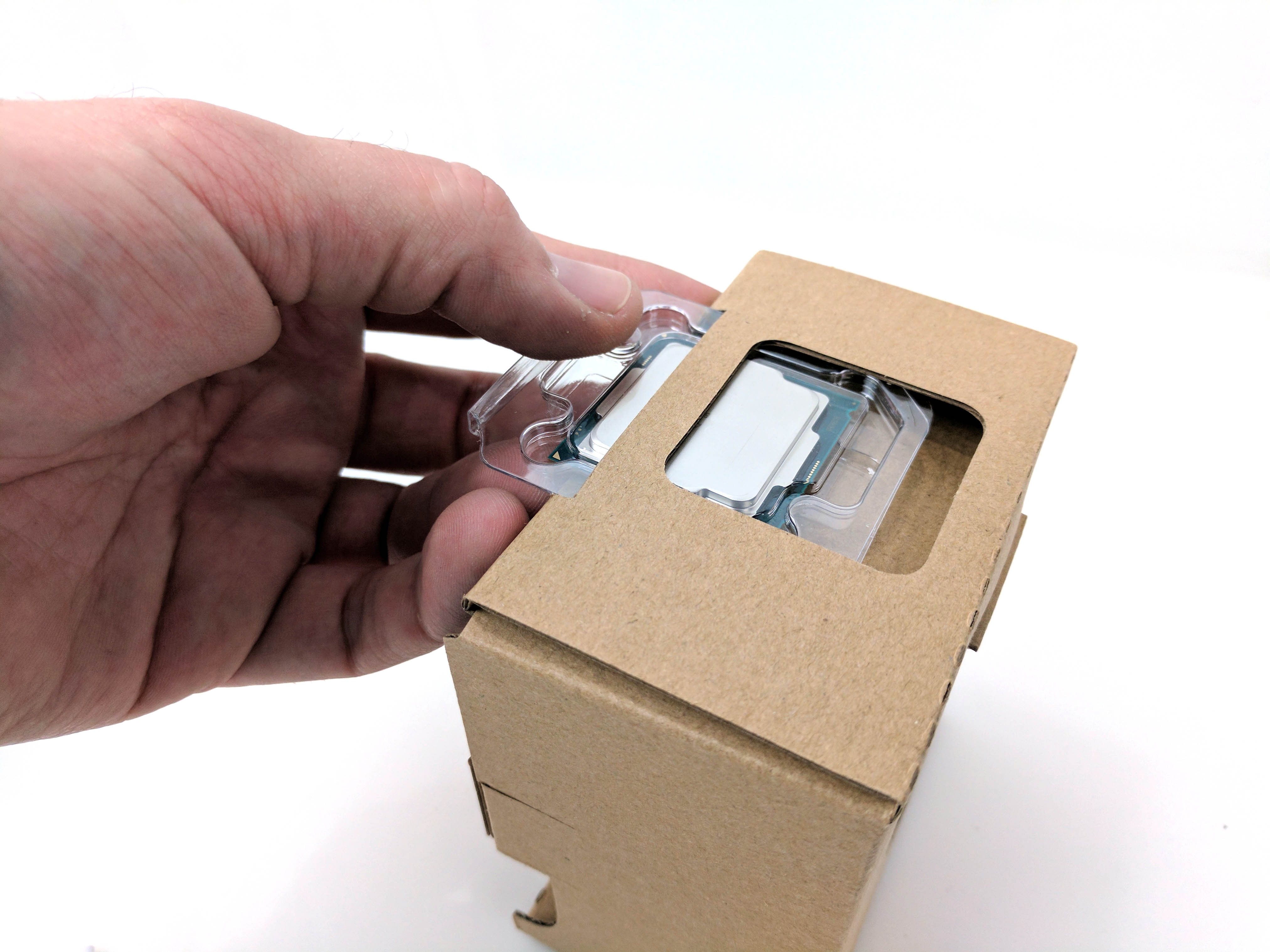
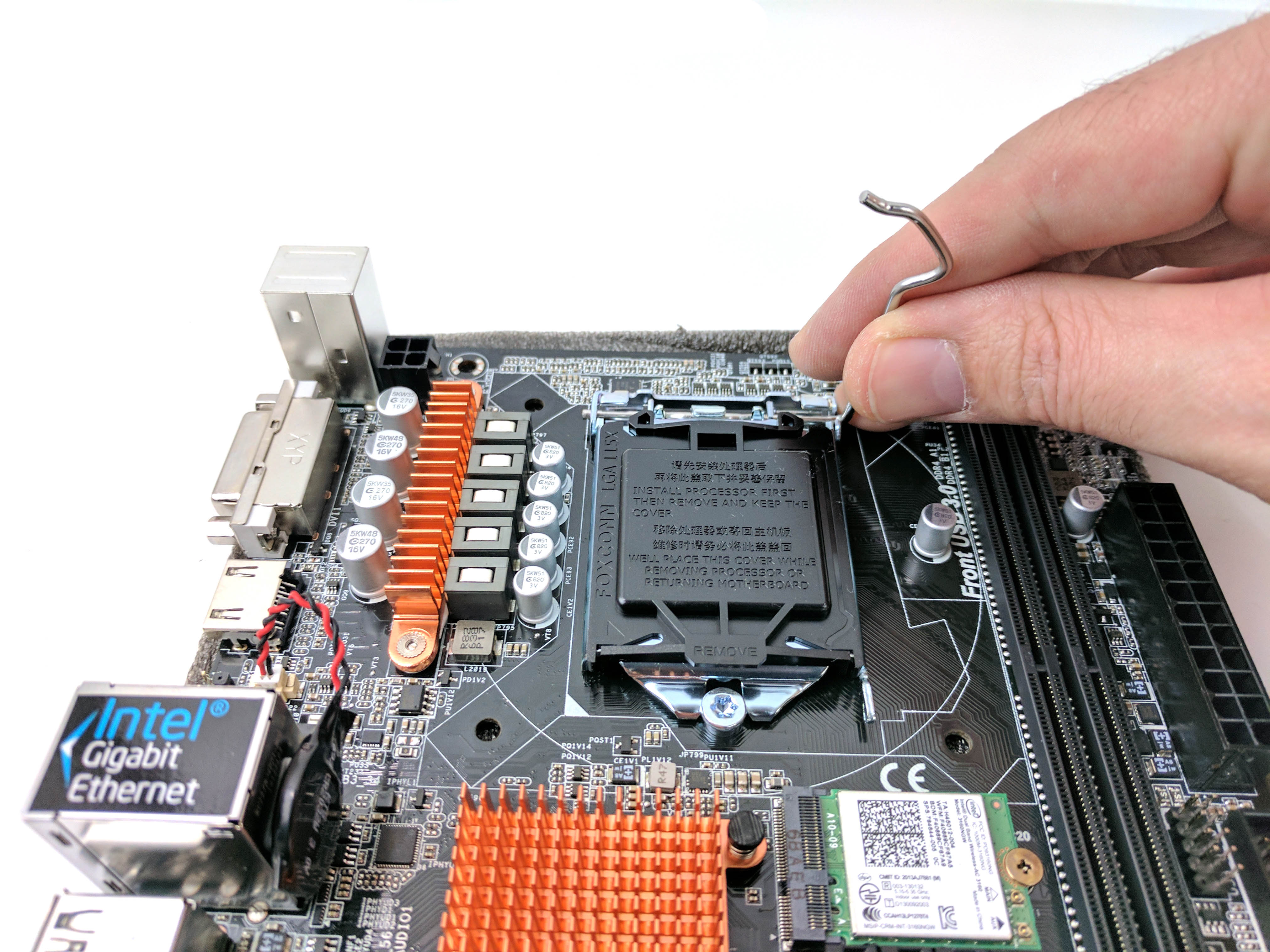
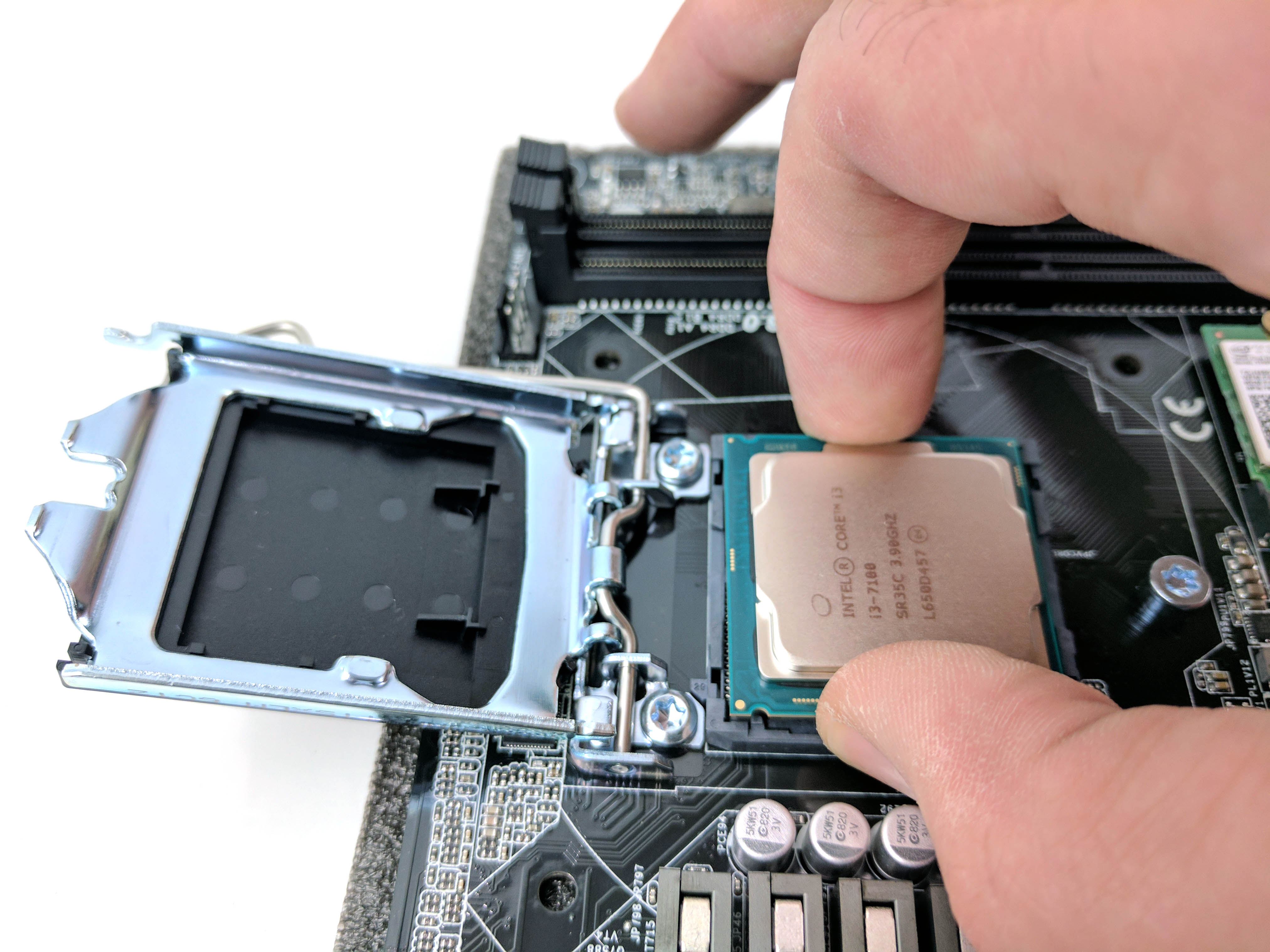
Place the ASRock H110M ITX/ac motherboard on a flat surface with its foam padding positioned underneath it (think of it as a motherboard coaster). Unbox the CPU (in this case, an Intel Core i3-7100) and stock Intel cooler.
Unhook the CPU socket arm on the motherboard and raise the clamp to expose the socket. Remove the CPU from its plastic case and locate and align the notches in the chip and motherboard and gently place the CPU in the socket (see the fourth slide above). Don’t forget to discharge any static buildup before handling the processor with an anti-static wrist band, or by simply touching a grounded metal object nearby.
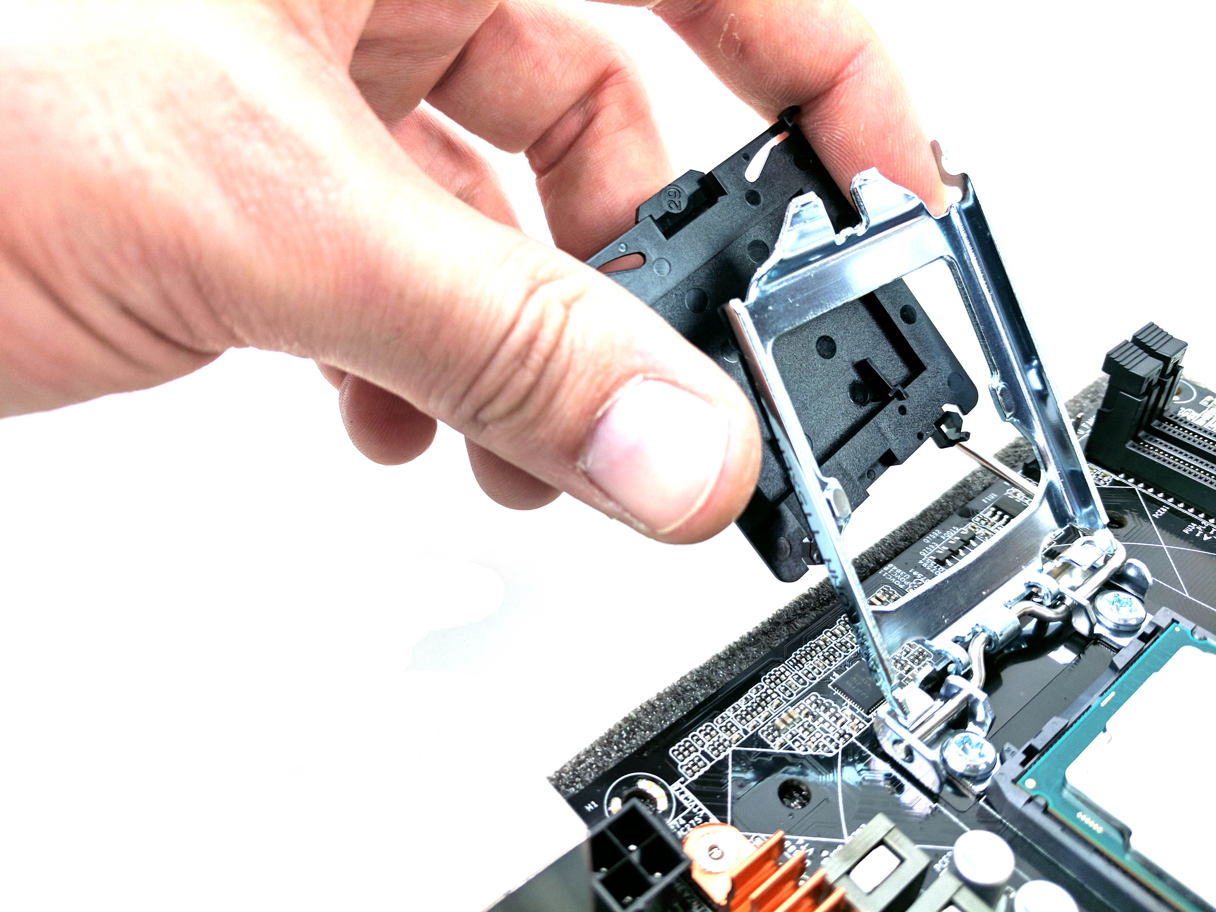
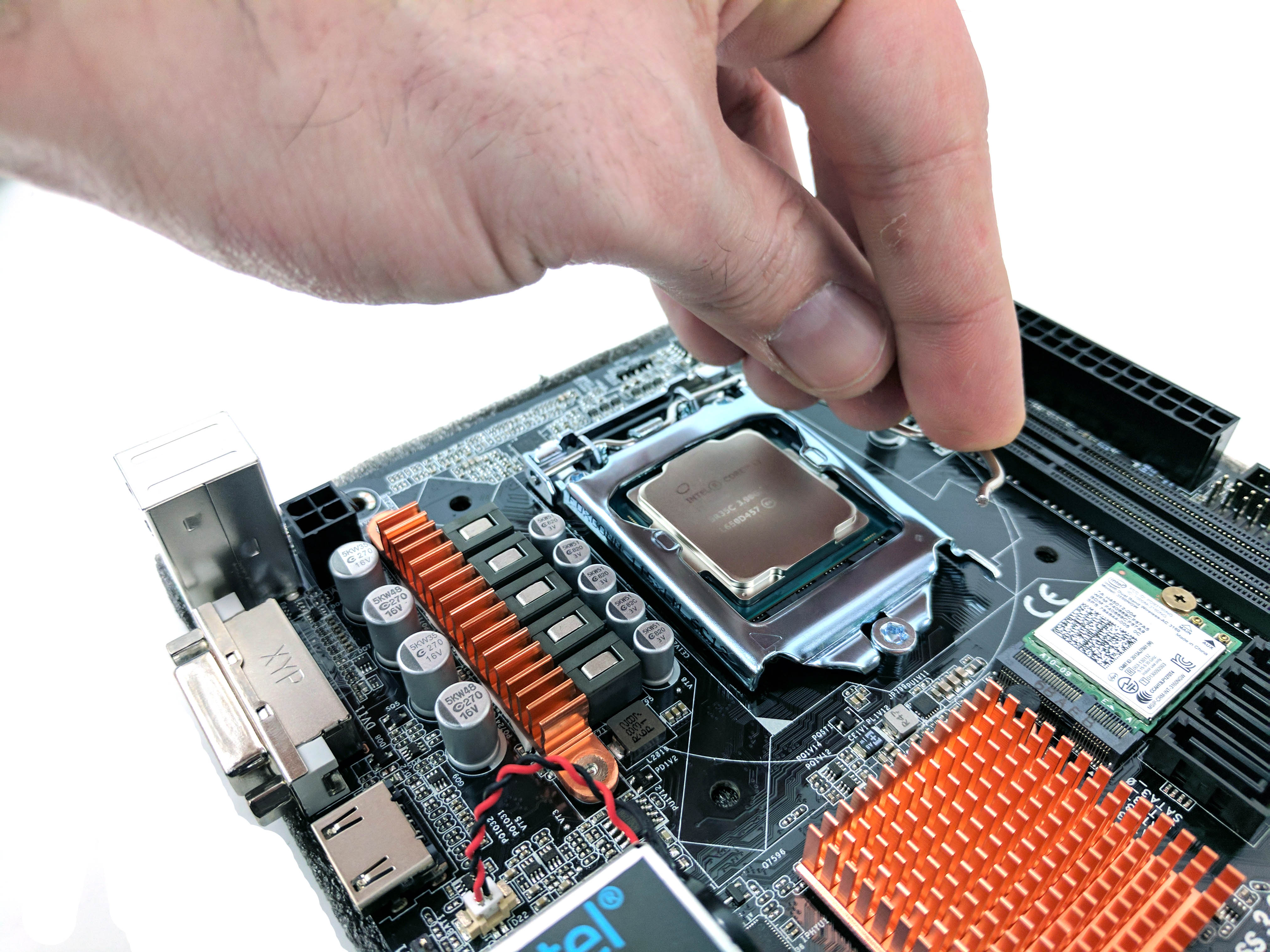
Remove the plastic cover on the clamp, lower it back into position, and lock the arm into place to secure the processor to the motherboard (slides 5 and 6 in the album above).
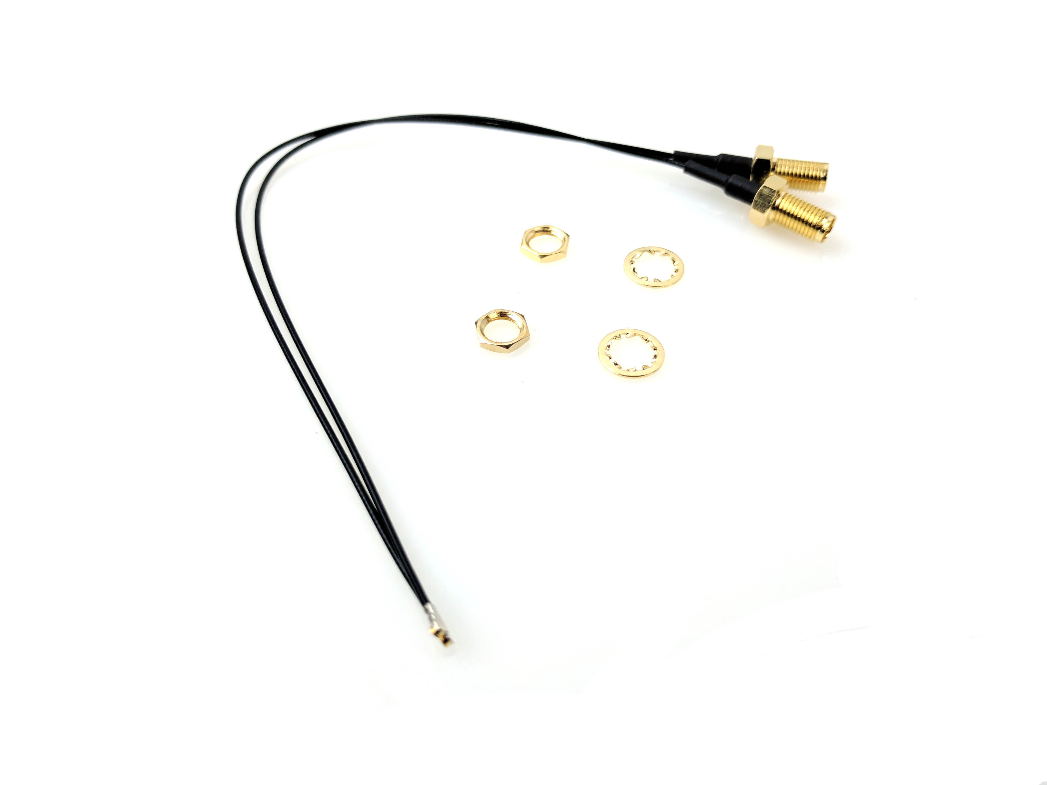
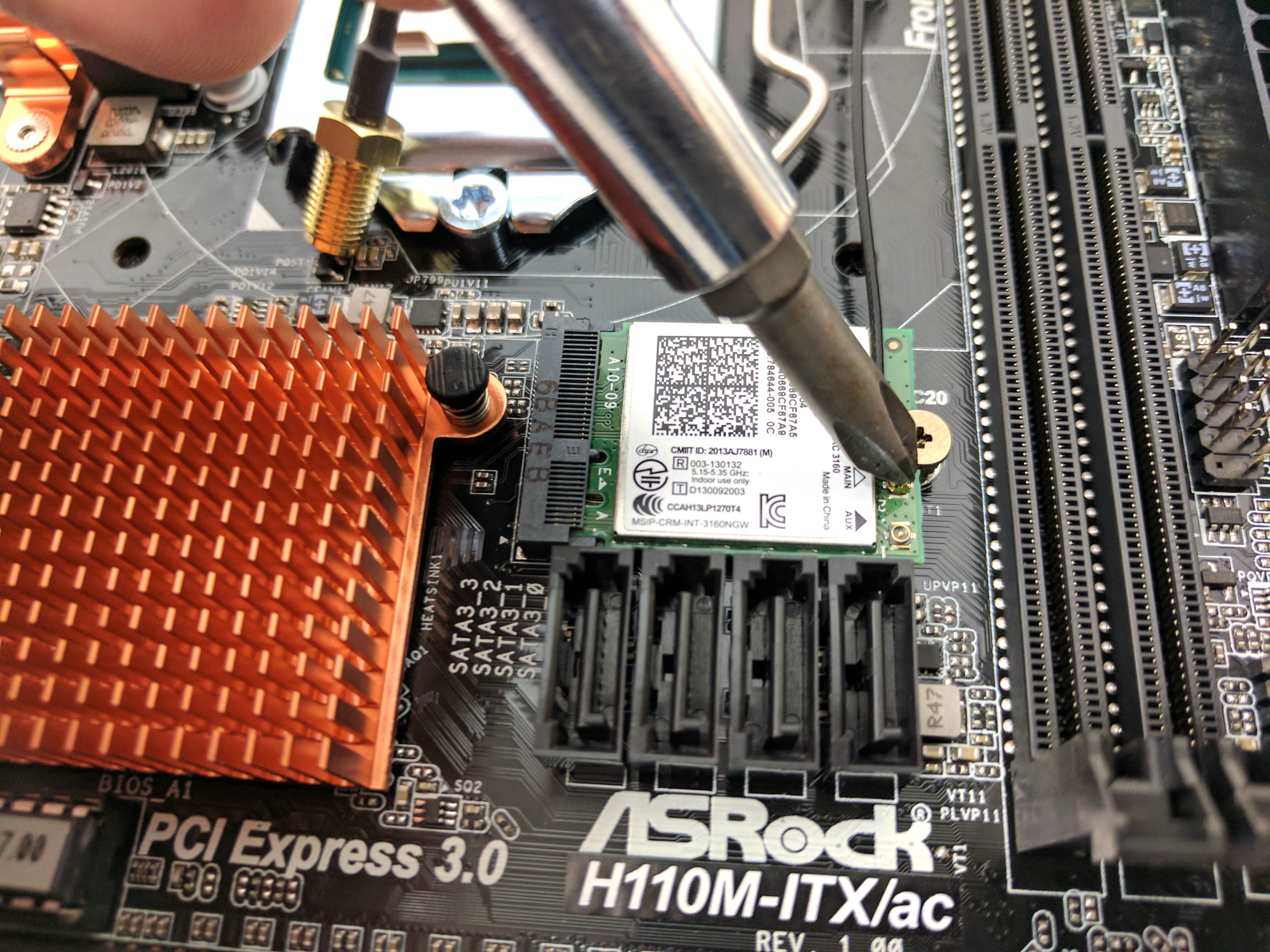
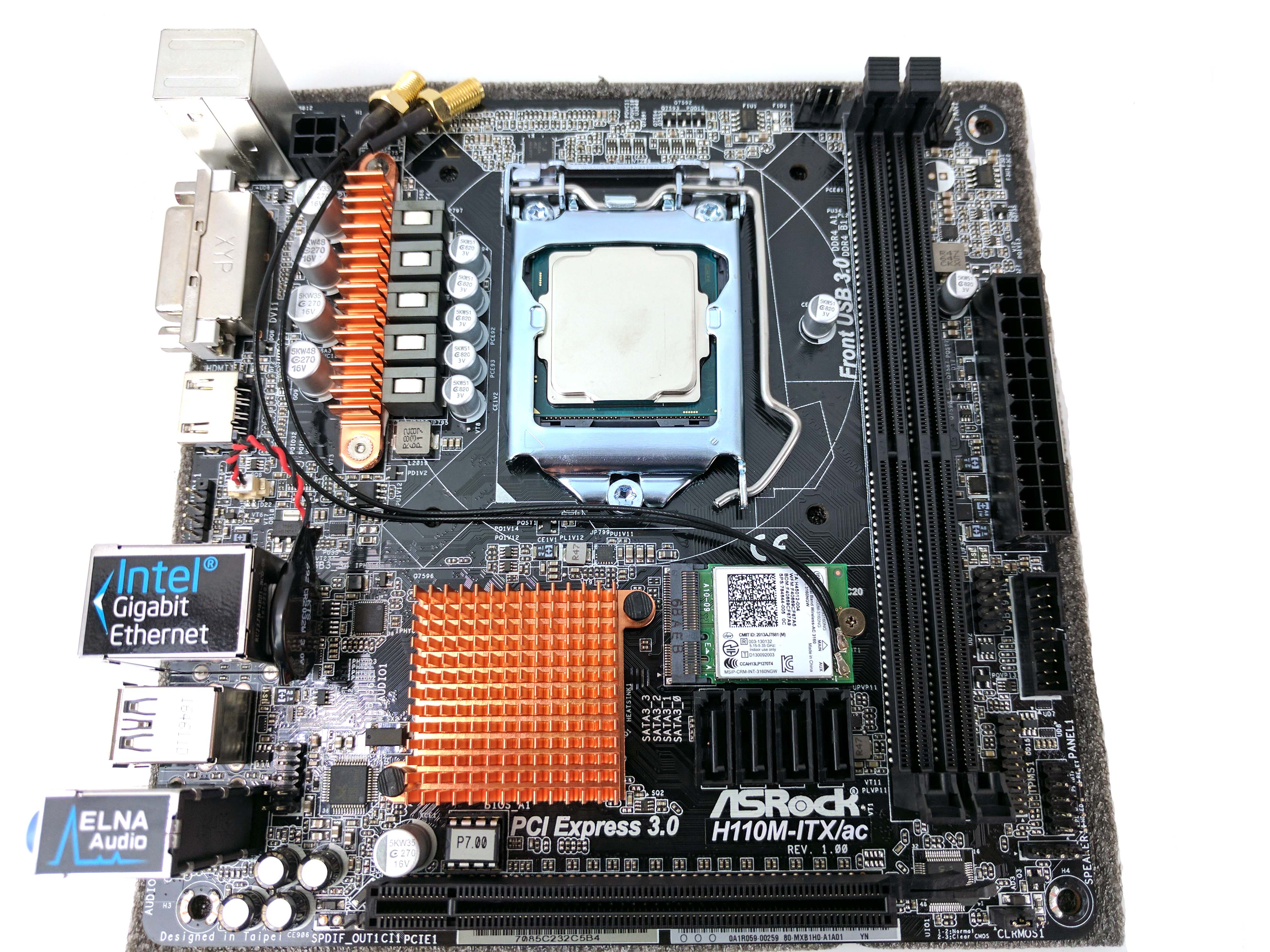
The motherboard comes with an Intel Wireless AC module installed, but you have to route the antenna wiring and attach it to the card and backplate yourself. So that we have plenty of clearance, we’ll hold off on installing the CPU cooler for the moment. Take the thin antenna cables (the 7th picture in the album above) and use the head of a small screwdriver to attach the leads to the WiFi card (the small M.2 device next to the memory DIMM slots). Run the antenna wiring towards the back panel I/O so that you can attach them to the rear I/O panel in the case once you mount the board.
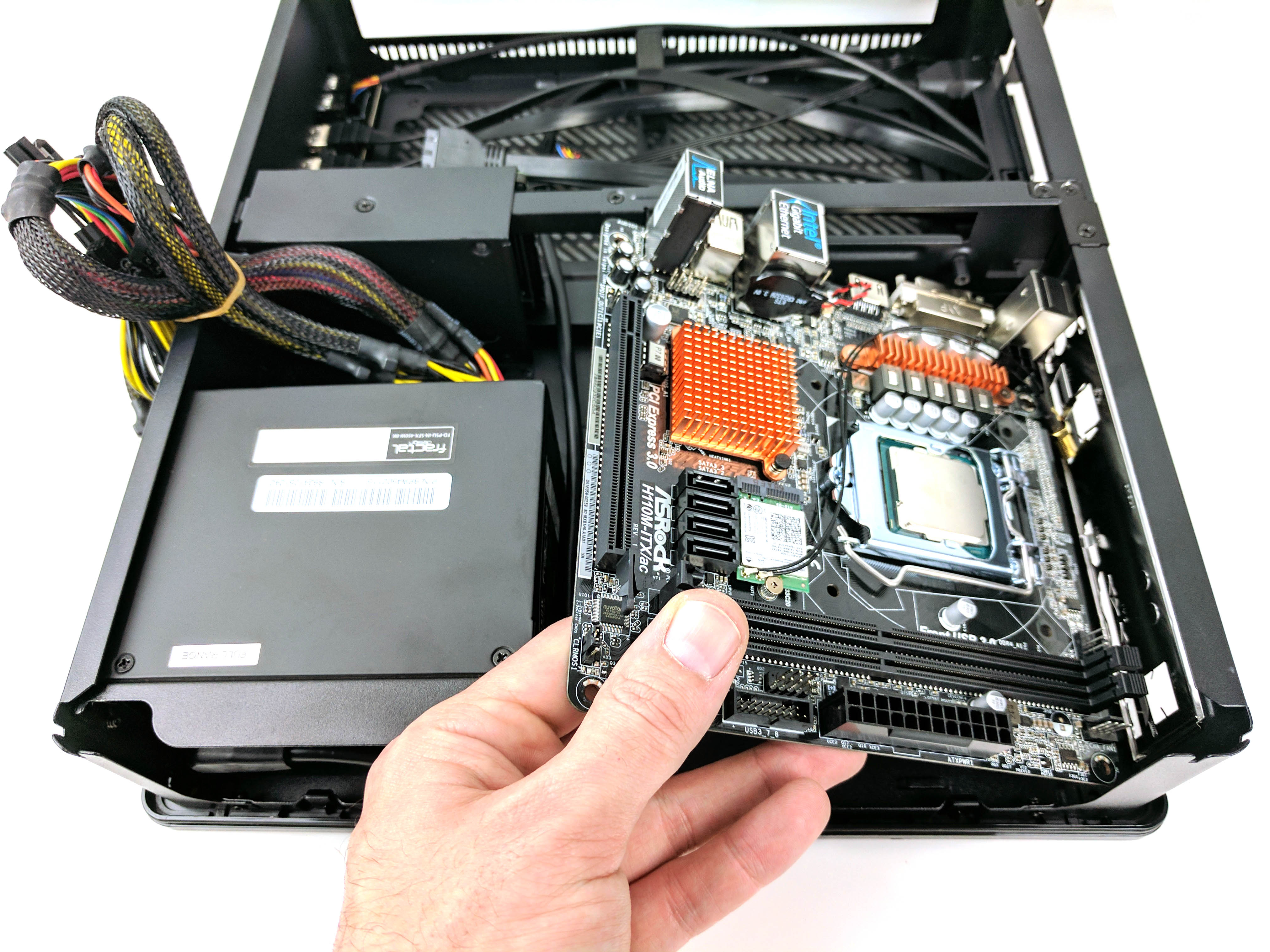
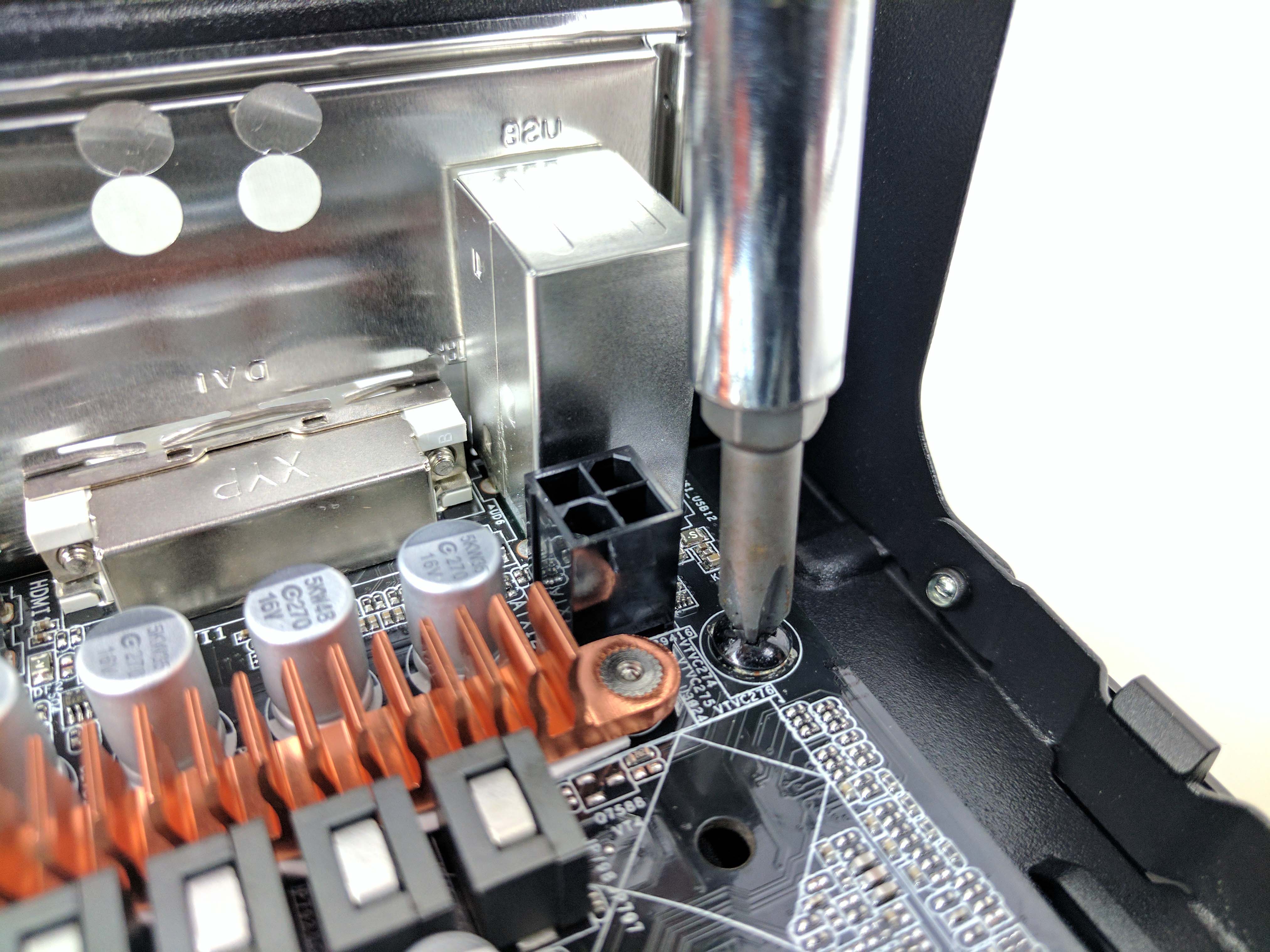
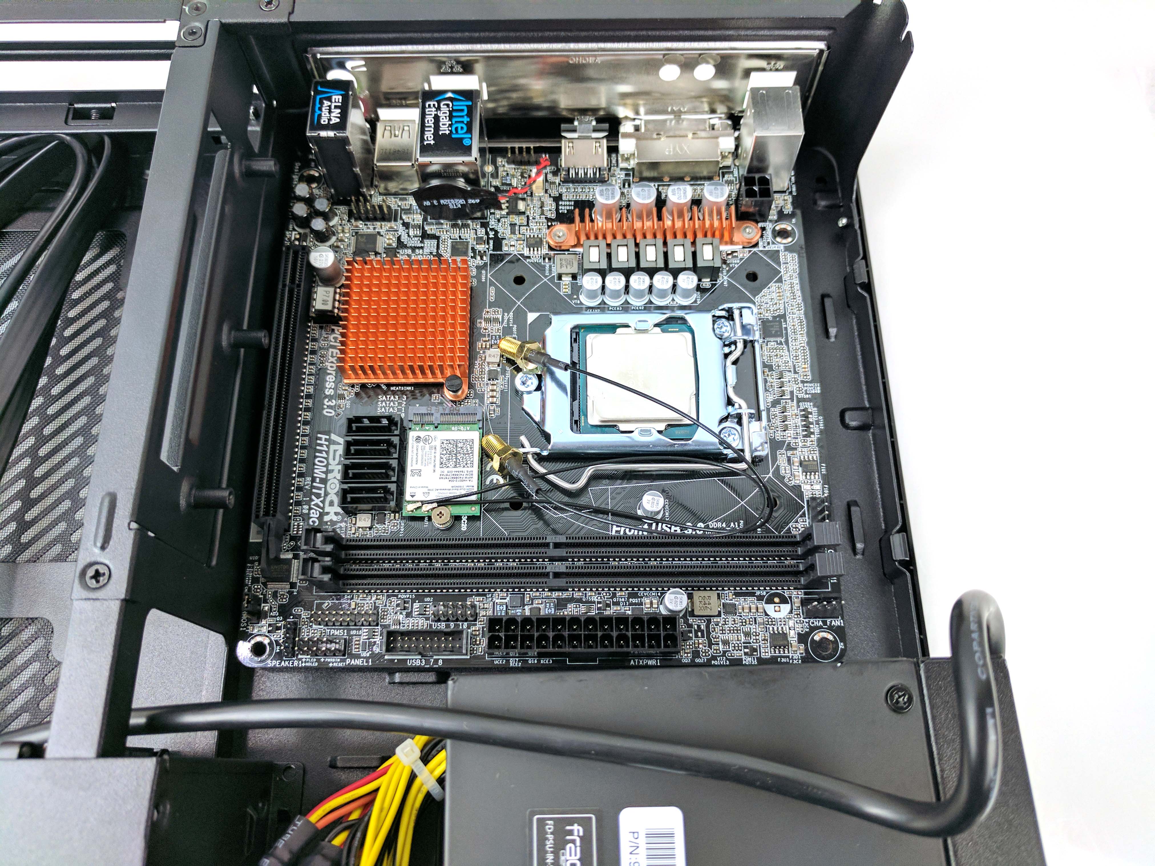
To install the motherboard and remaining components, begin by locating the short Philips-head screws that came with the case. Use four screws with the thicker threads to attach the motherboard to the chassis. You’ll also need the thinner screws later, so set them aside. Lower the motherboard into the chassis and line up the mounting holes to those of the case (slide 2 above)).
Be sure to align the motherboard’s rear I/O ports to the backplate so that nothing is bending or blocking a port. It’s also important to mind the WiFi antenna wiring, which will simply rest on the board as you install it. You may also have to lift away the primary ATX power cable (the big one) coming off the PSU to be able to land the motherboard properly.
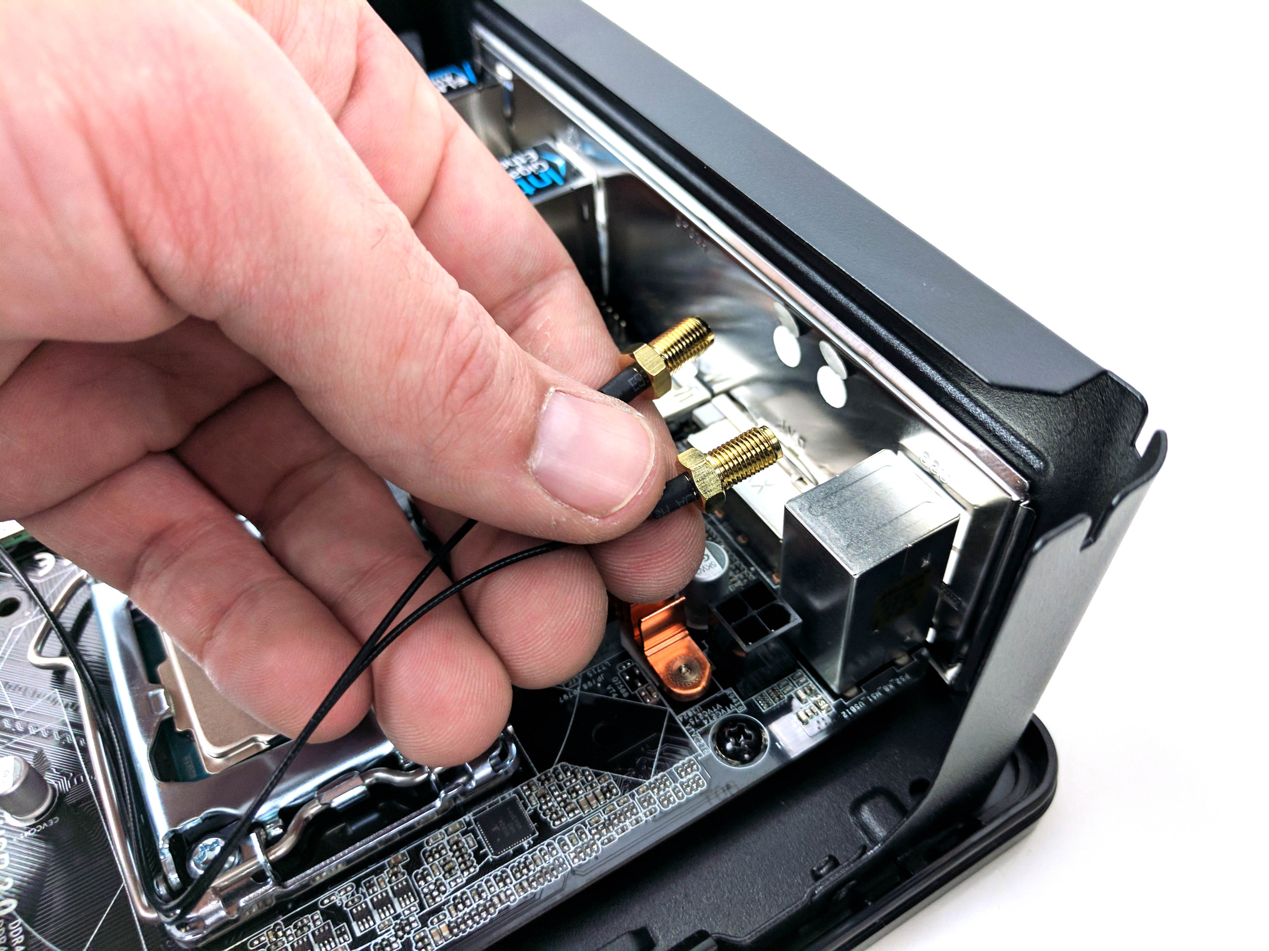
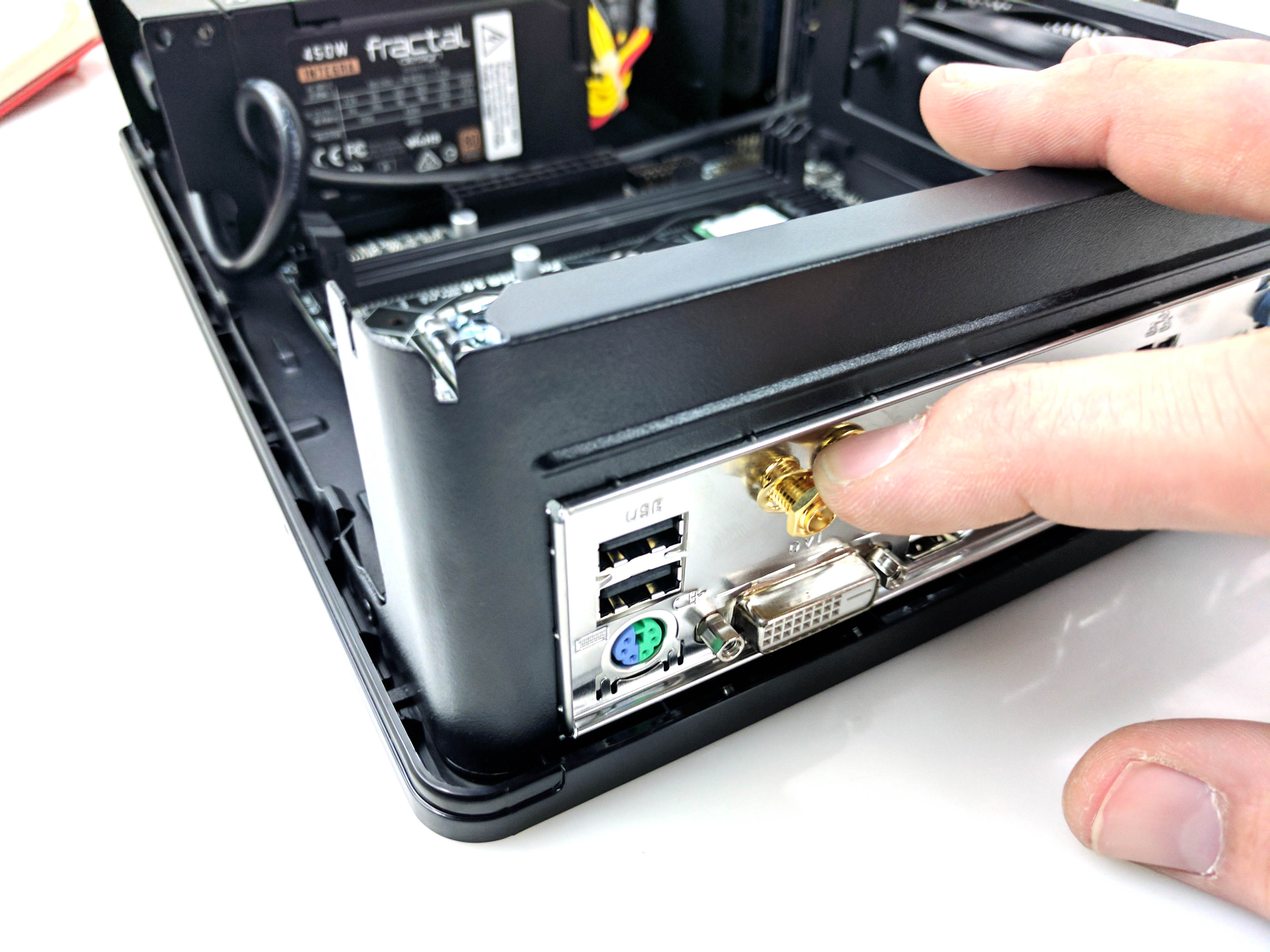
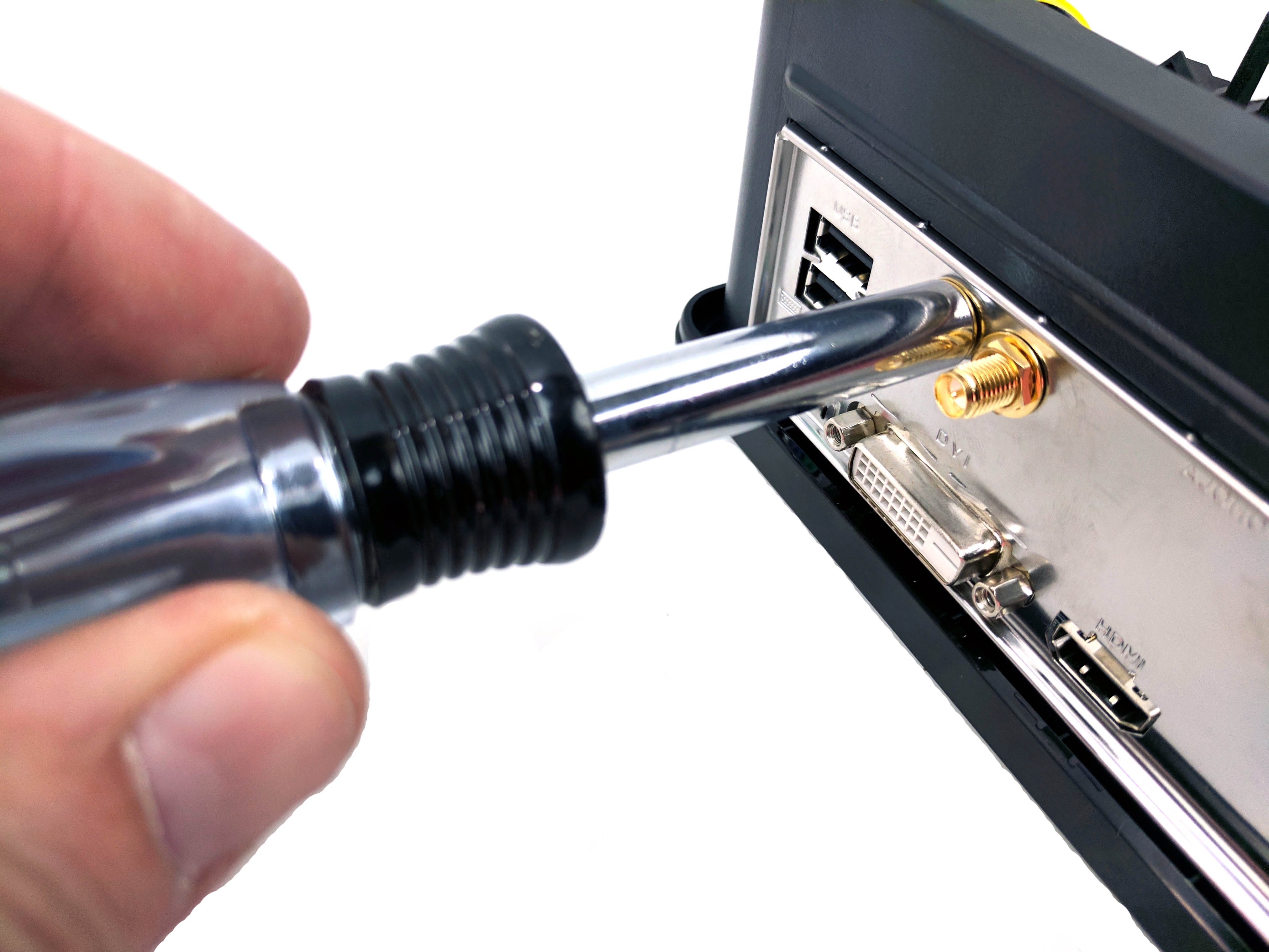
Secure the motherboard with the screws in each of its four corners (slide 4 above) and feed the WiFi antenna threads through the motherboard backplate (slide 5 above).
Secure the threads to the backplate with the provided washer and nut (small, gold-colored). You can start threading it with your fingers, but then you can use a pair of pliers to tighten the nut. If you have one handy, we found that a reversible screwdriver’s shaft (take out the screwdriver tip) was just the right size for it.
The Cooler
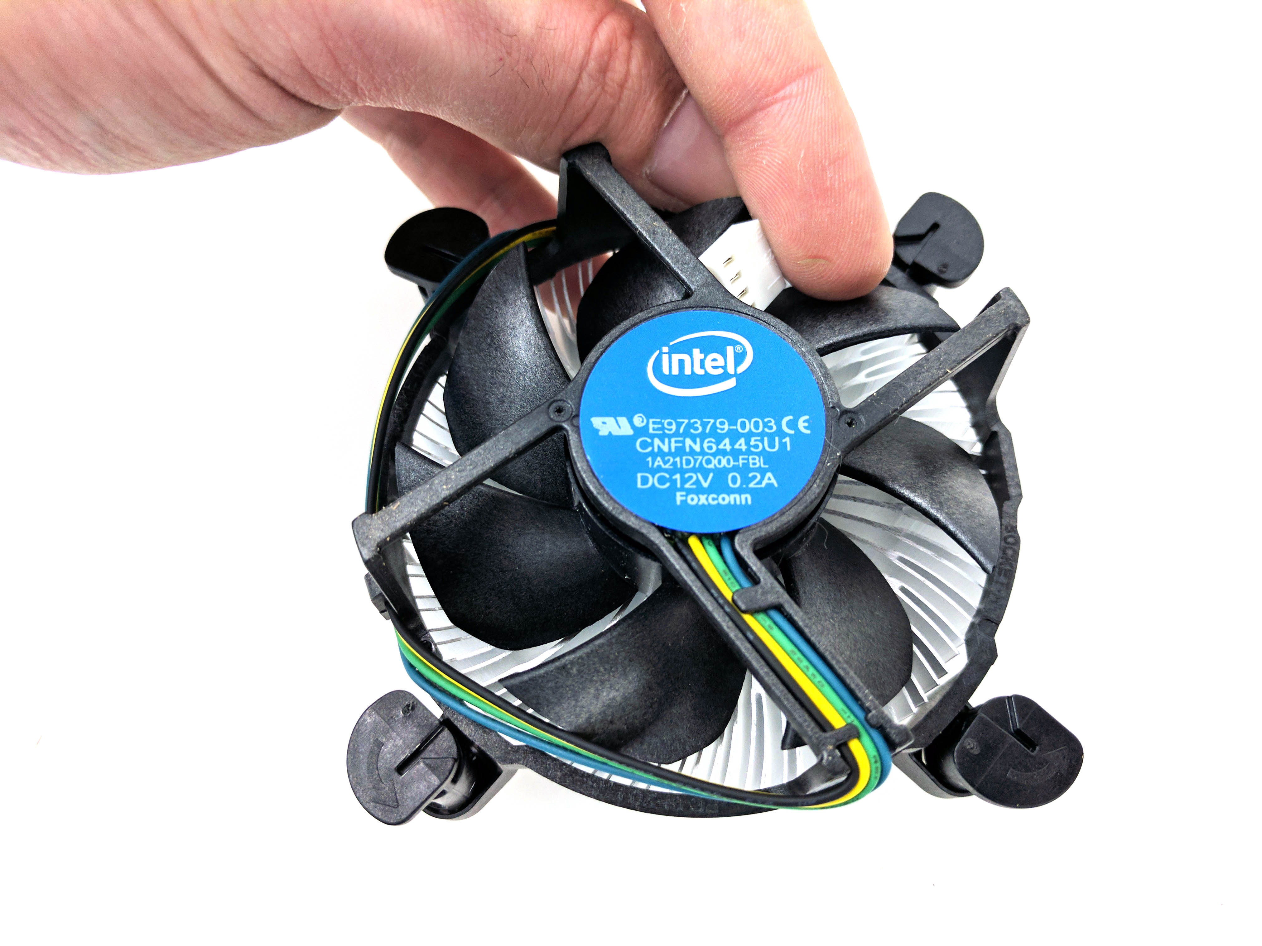
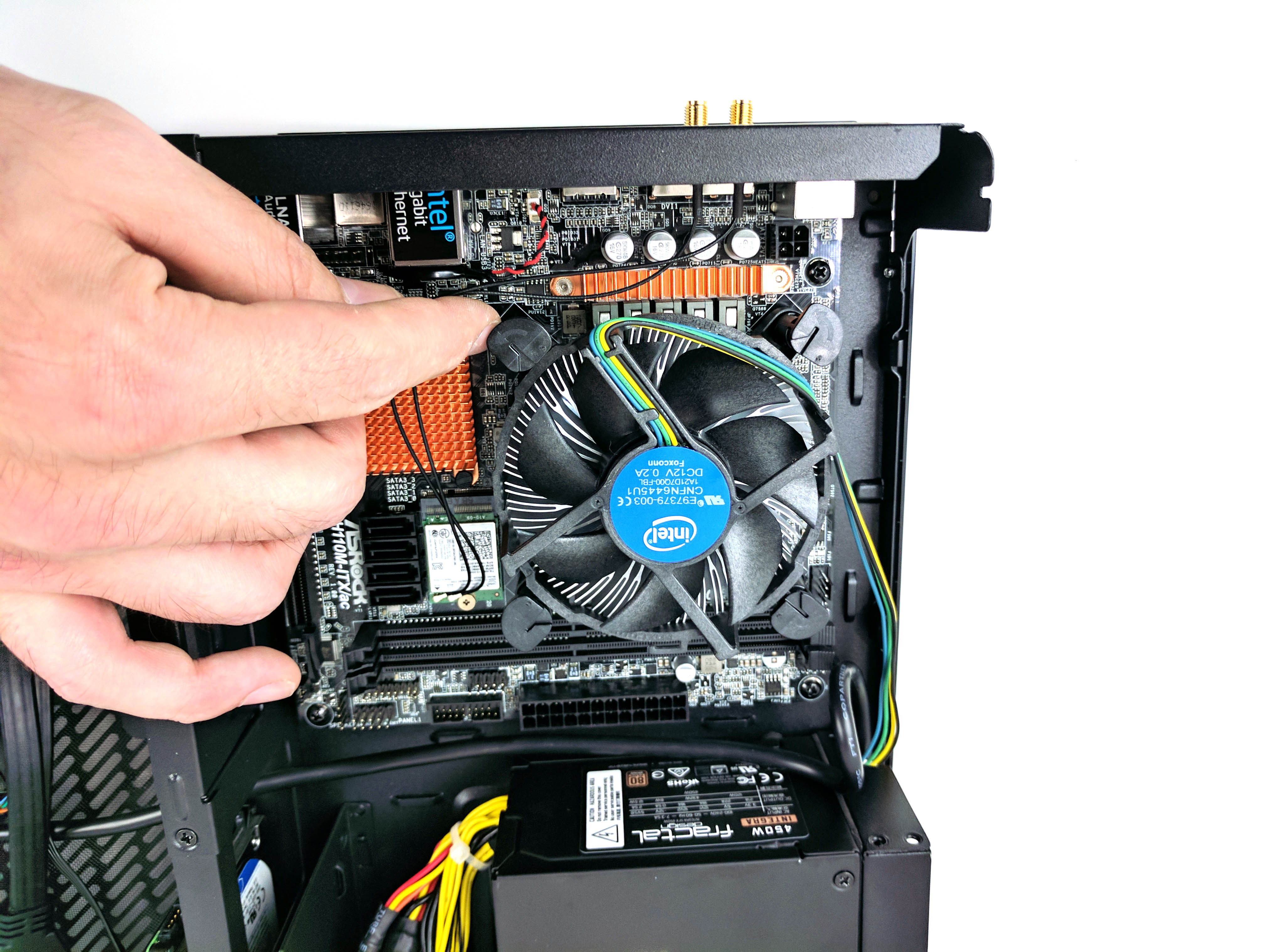
Take the stock Intel CPU heatsink and fan out of its box and untangle its fan cable.
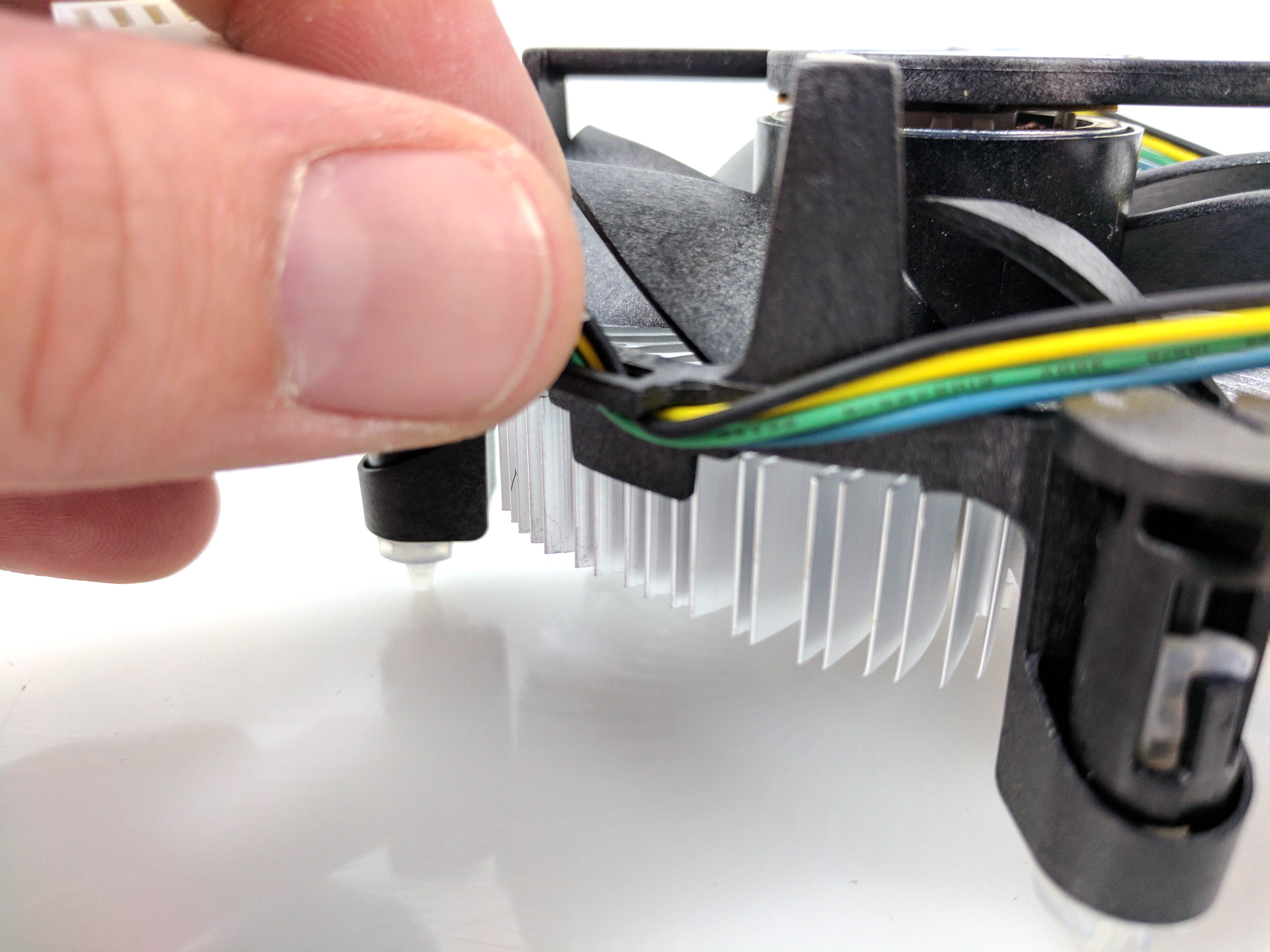
You should remove the wiring from the plastic hook on the heatsink to give yourself enough slack to reach the fan port (see slide 2 above). Also make sure that the fan can spin freely, without hitting the cable.
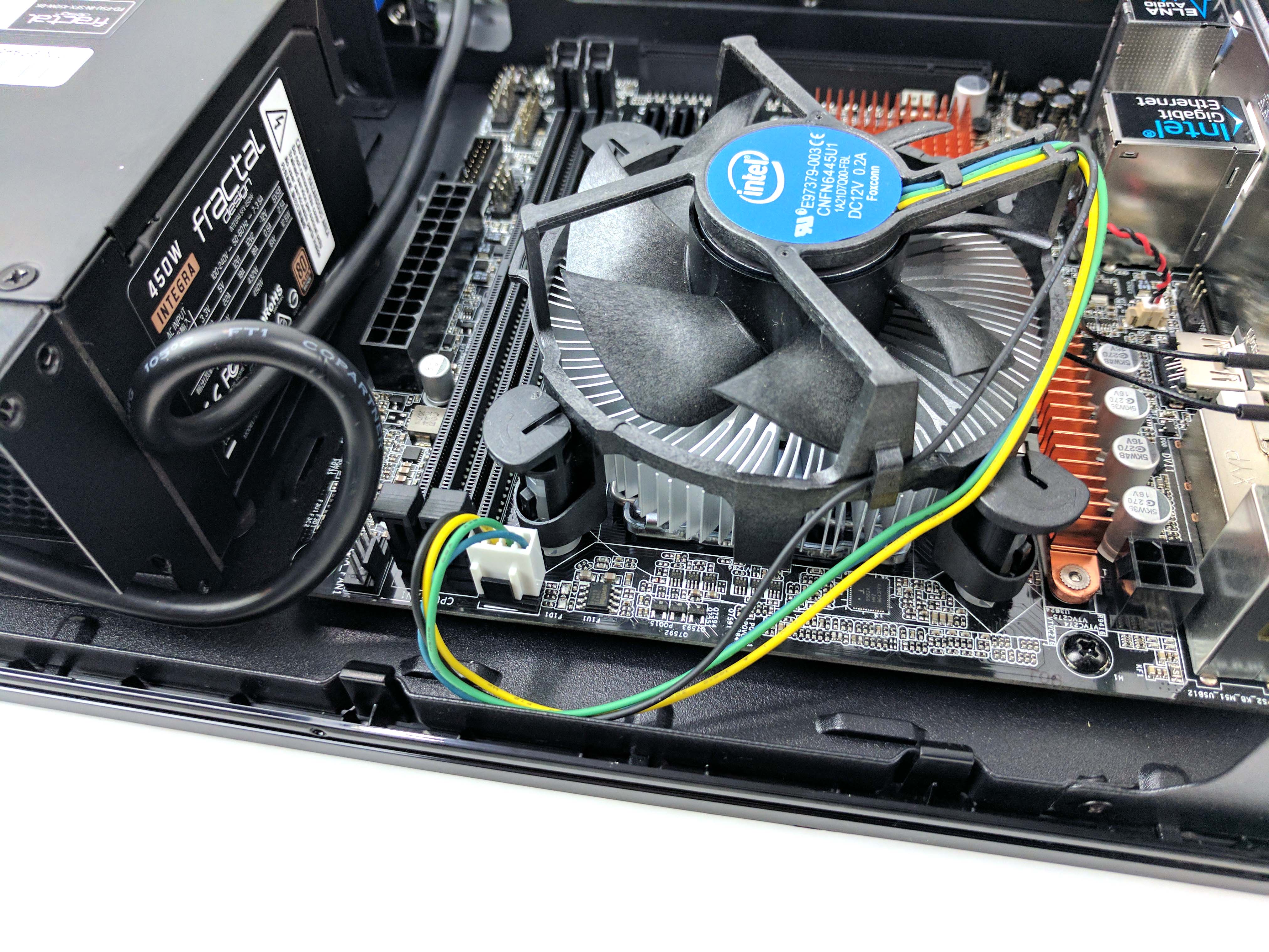
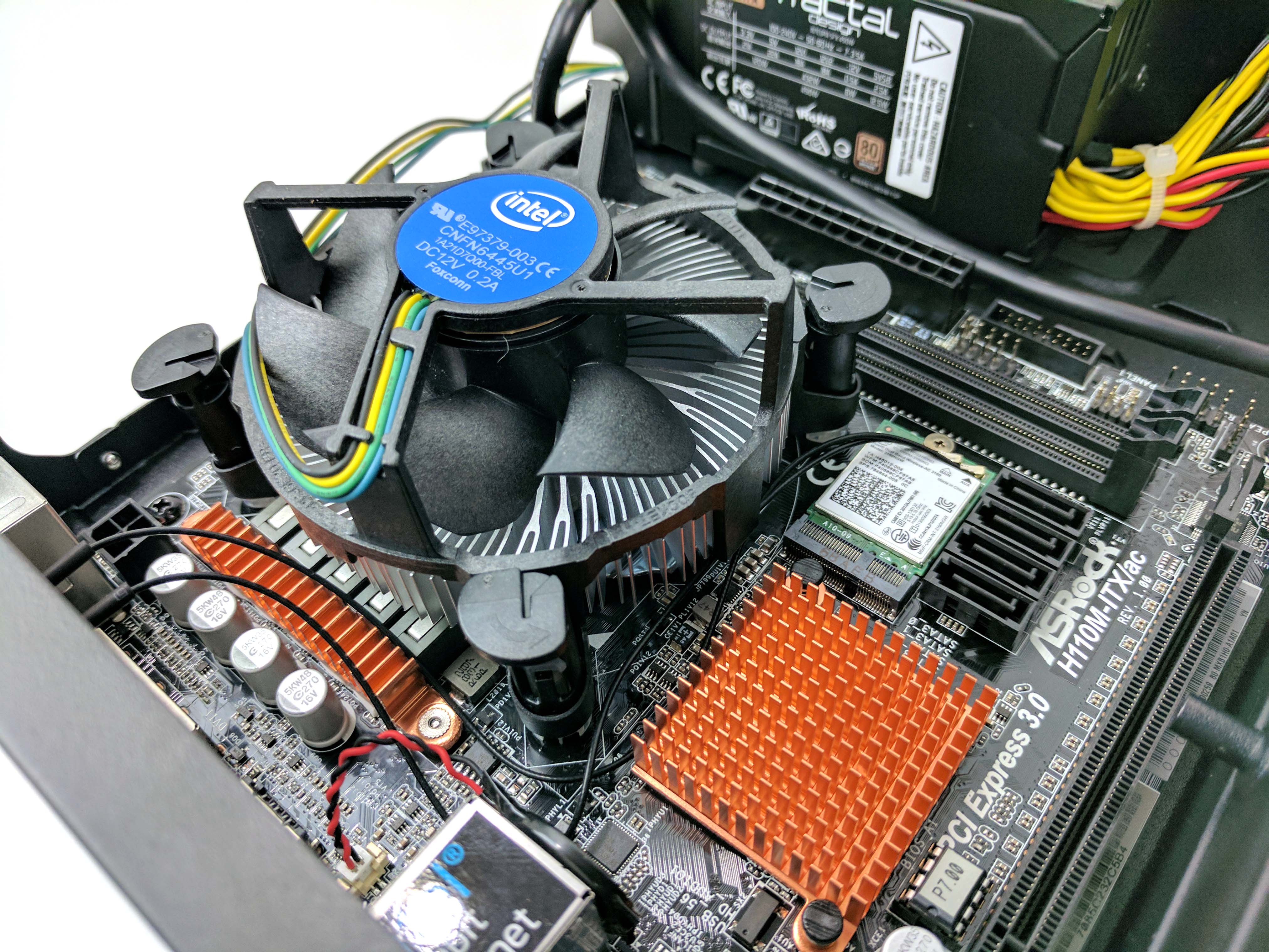
Line up the white plastic pegs of the CPU cooler to the corresponding holes in the motherboard directly over the mounted CPU and socket (see slide 4 above). When it’s all lined up, apply pressure in opposite corners to secure it to the motherboard. Make sure the WiFi antenna cables are clear of the heatsink before locking it into place.
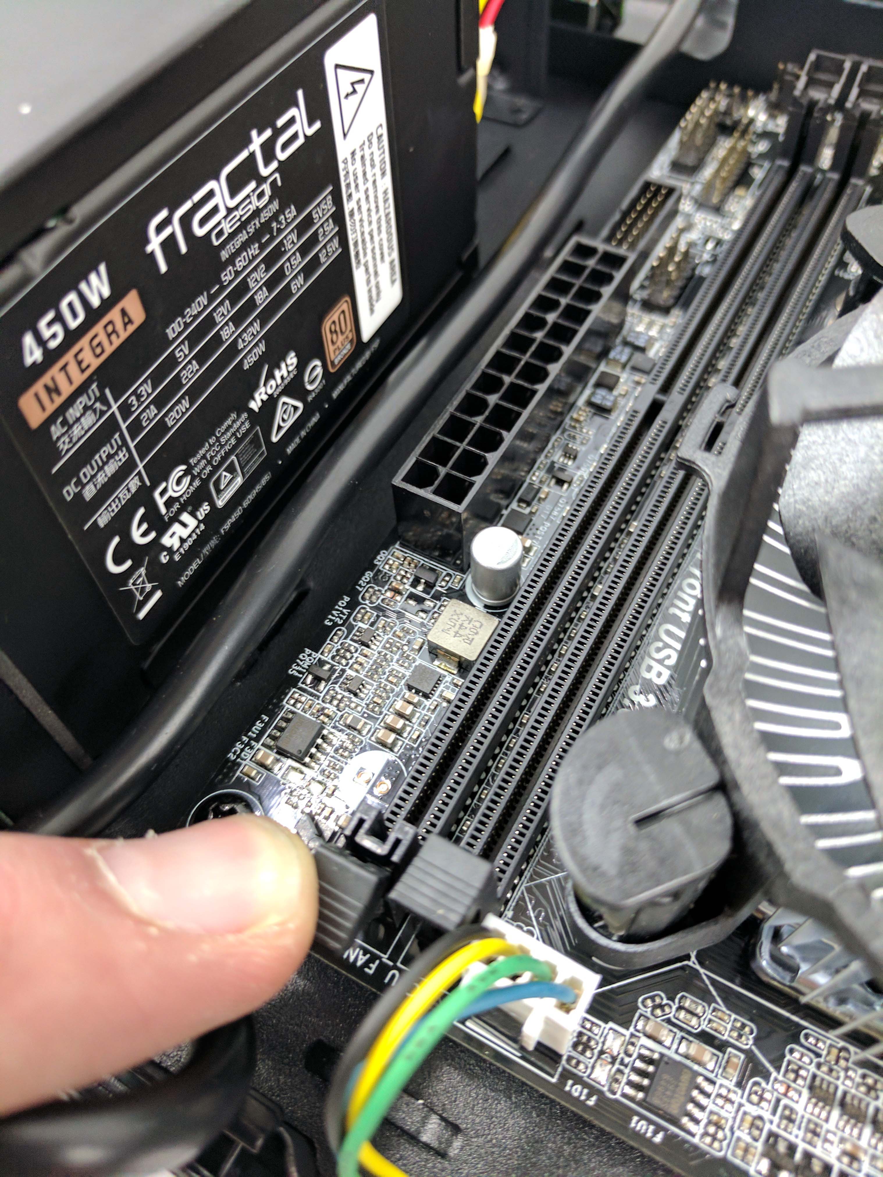
Plug in the heatsink’s fan to the CPU fan port on the motherboard, which is located next to the memory DIMMs (see slides 5 and 6 above).
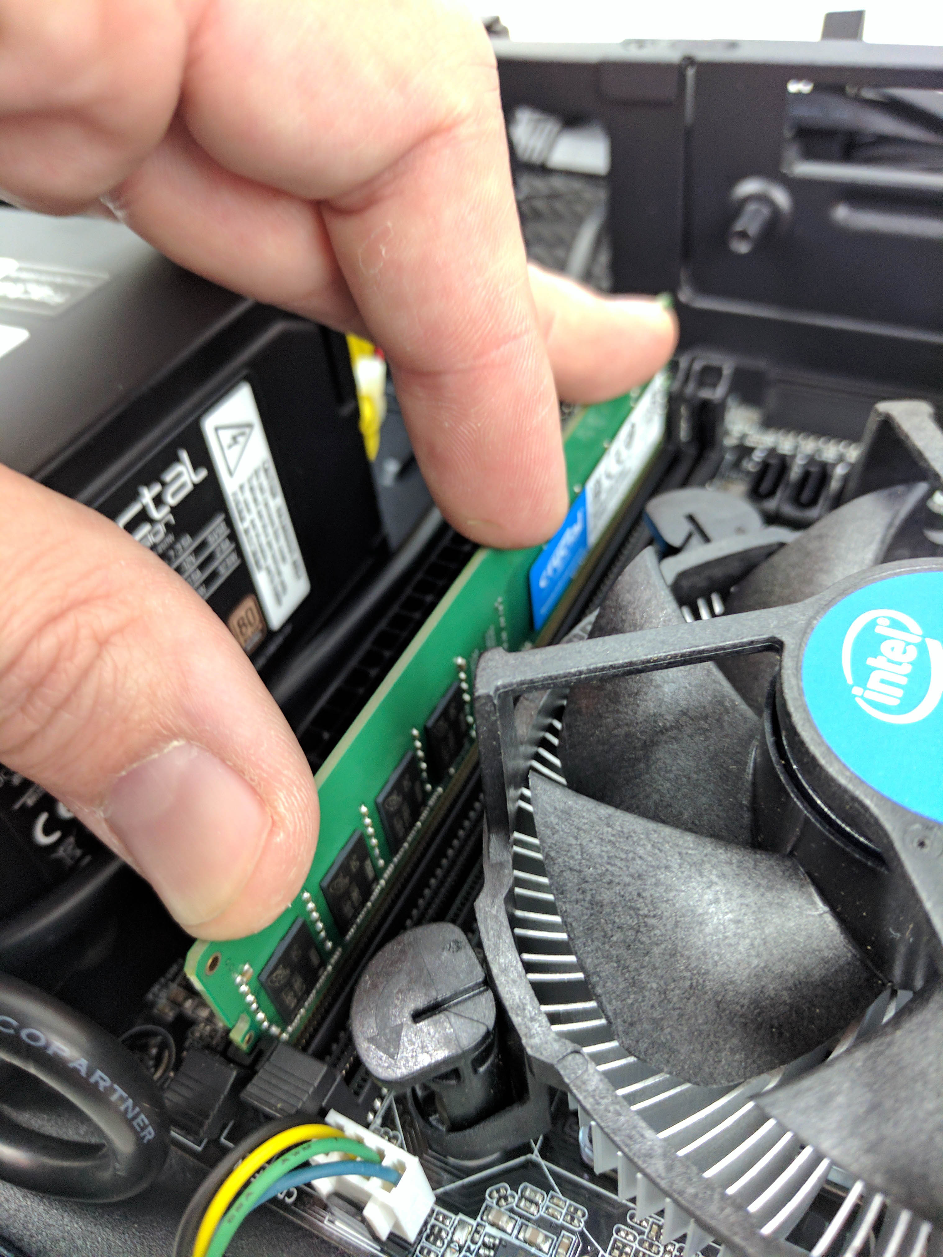
Speaking of which, open the latch and install the single 8GB of DDR4-2133 (making sure its properly seated and locked) in the memory slot furthest from the CPU, next to the ATX power plug (see the last picture in the album above). Speaking of which...
The Power Supply
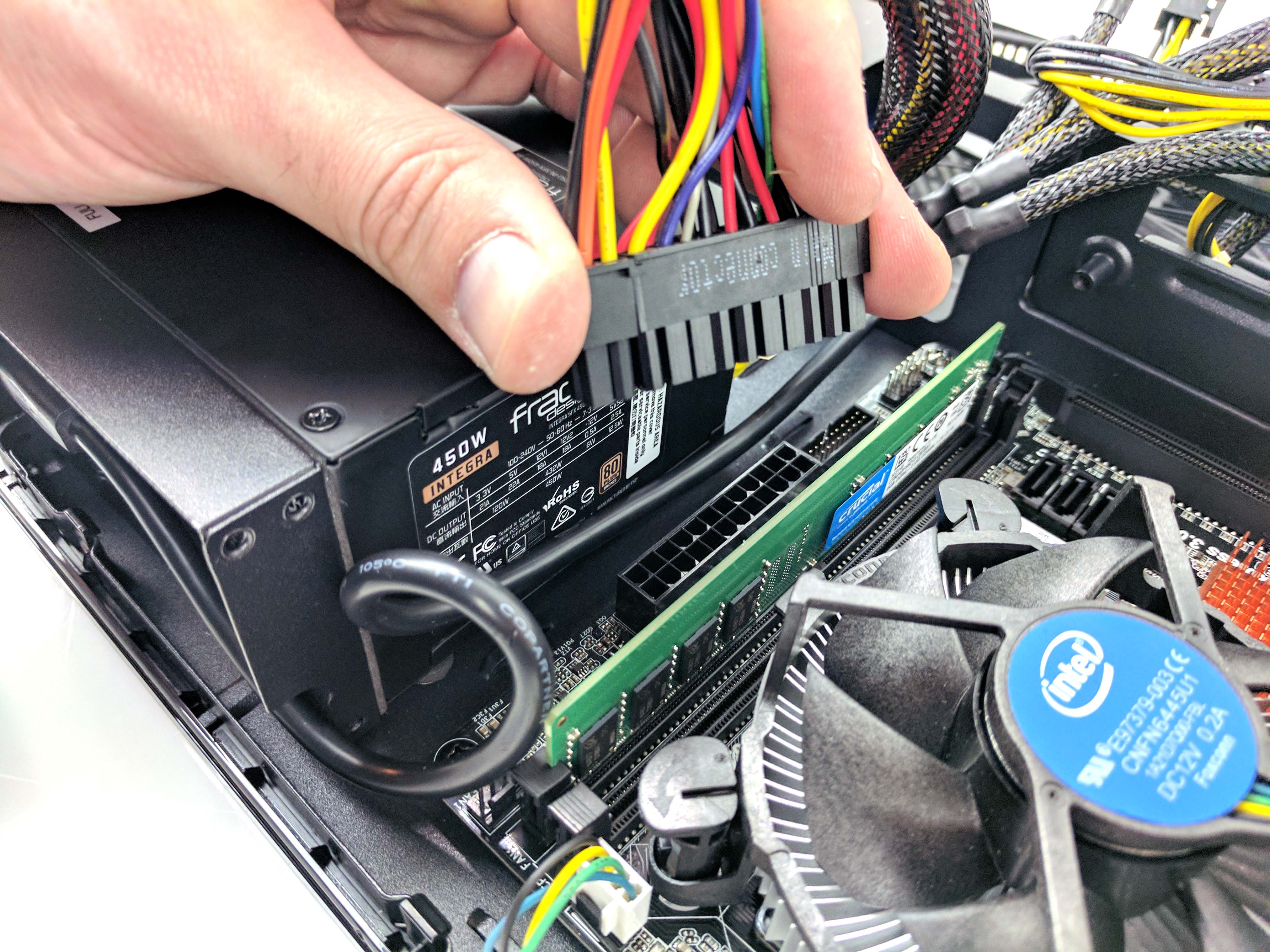
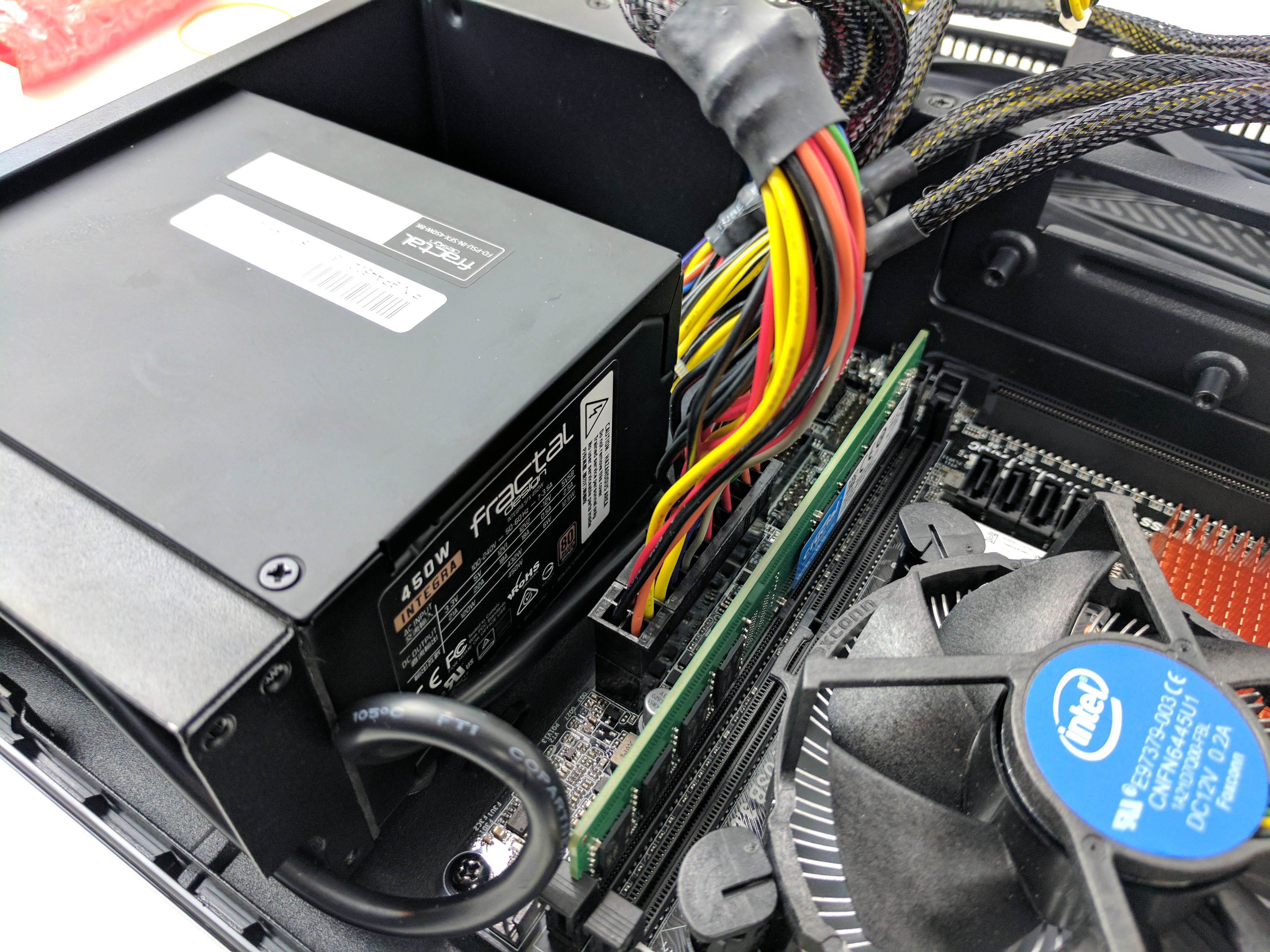
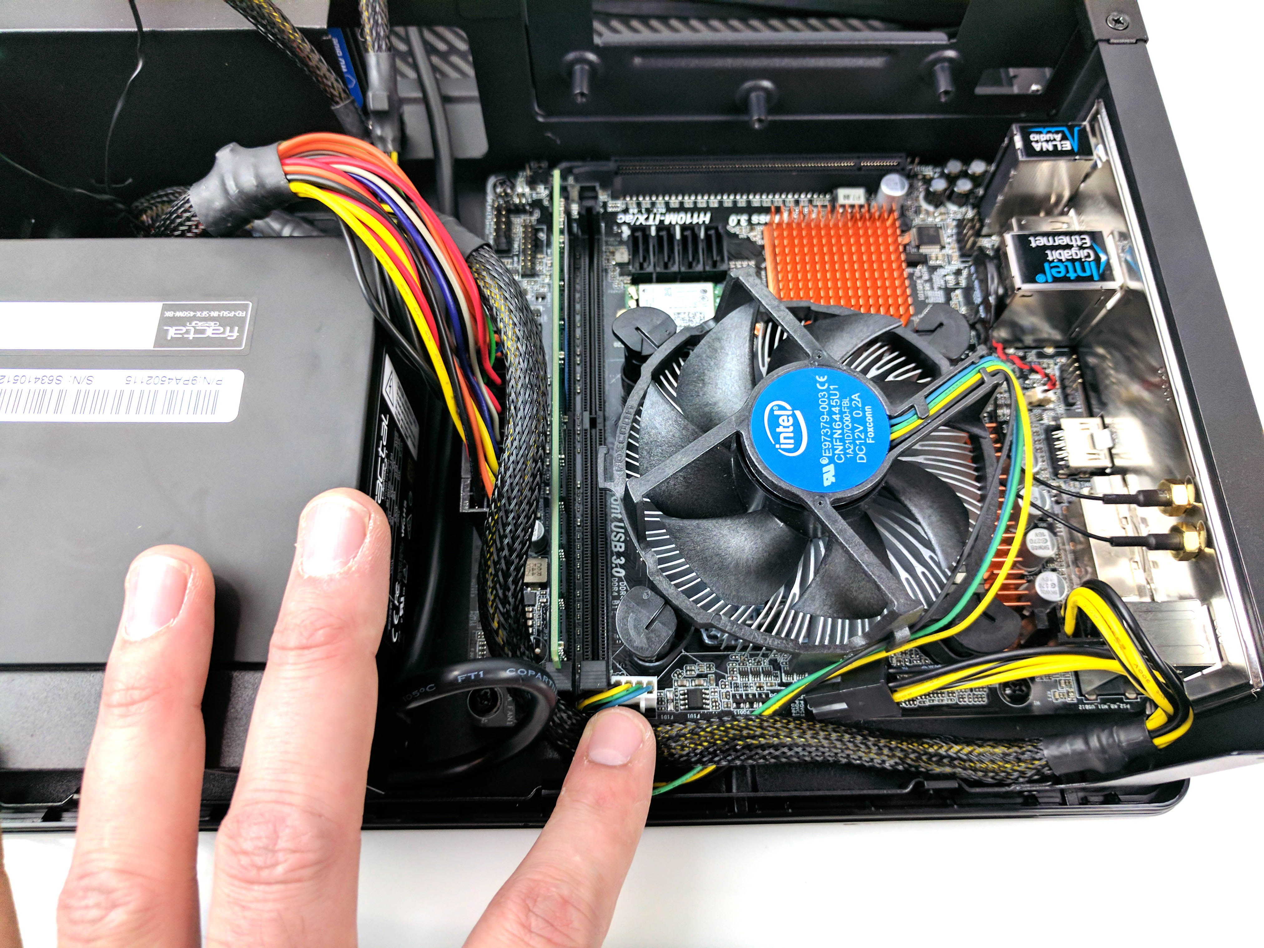
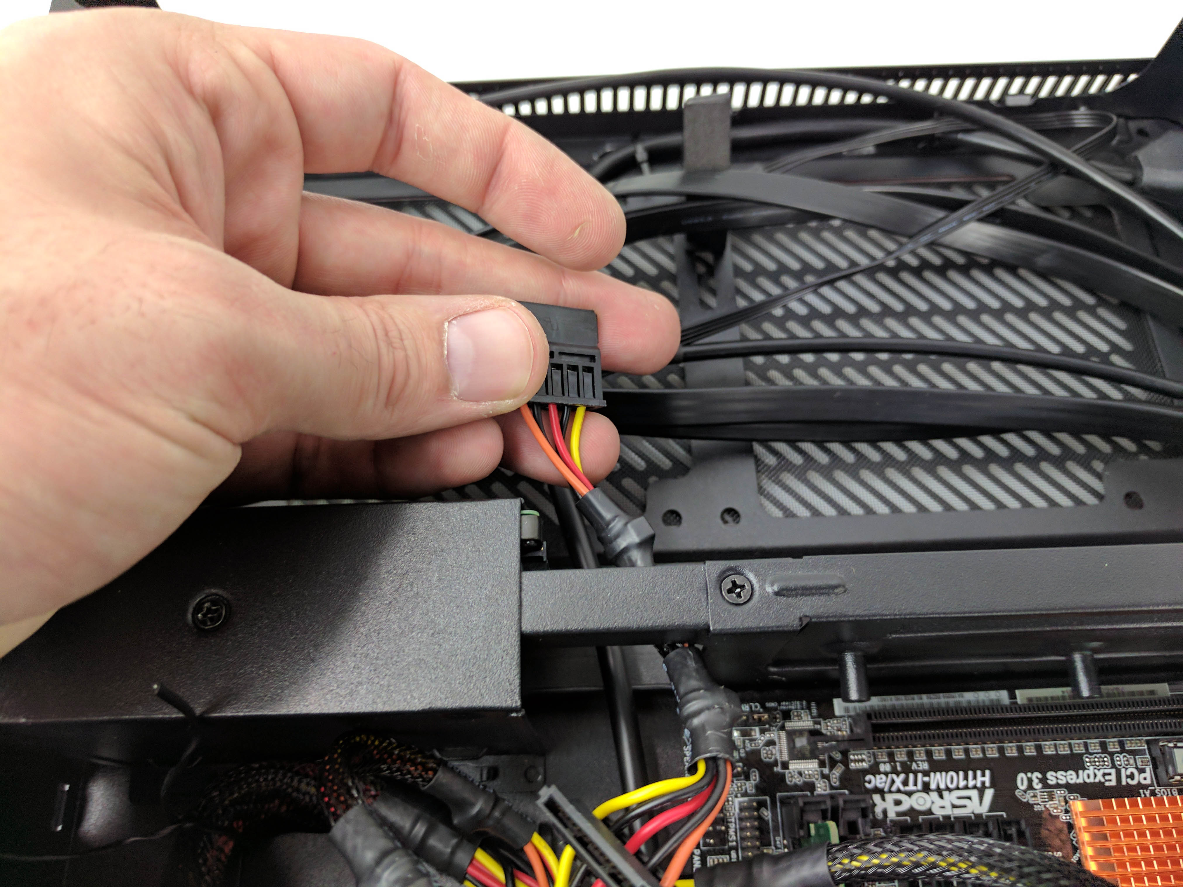
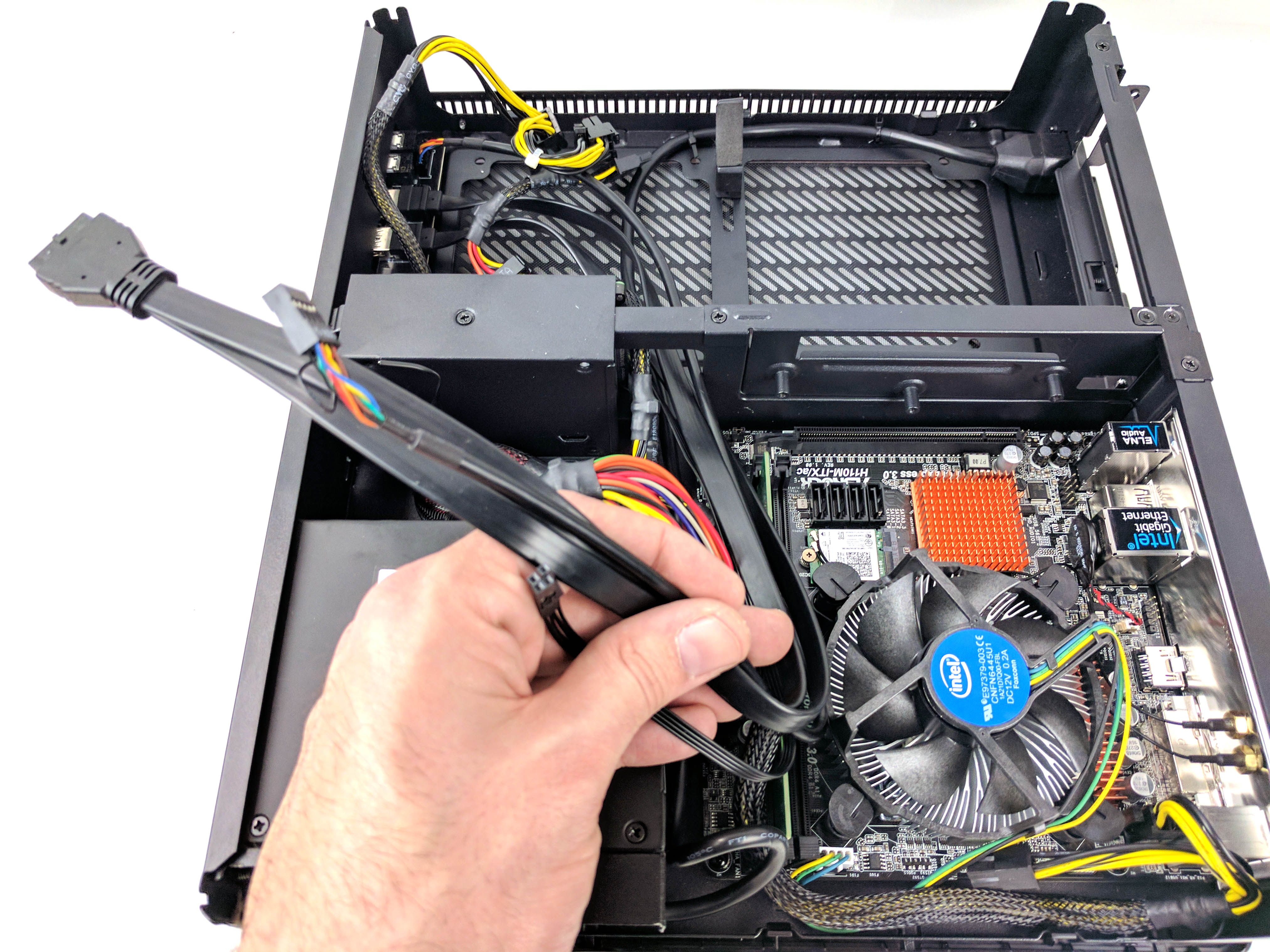
Connect the power supply’s 24-pin ATX power cable to the port on the motherboard (see slide 1 directly above), making sure to run the excess neatly into the open space of the case (where the PSU cables originate).
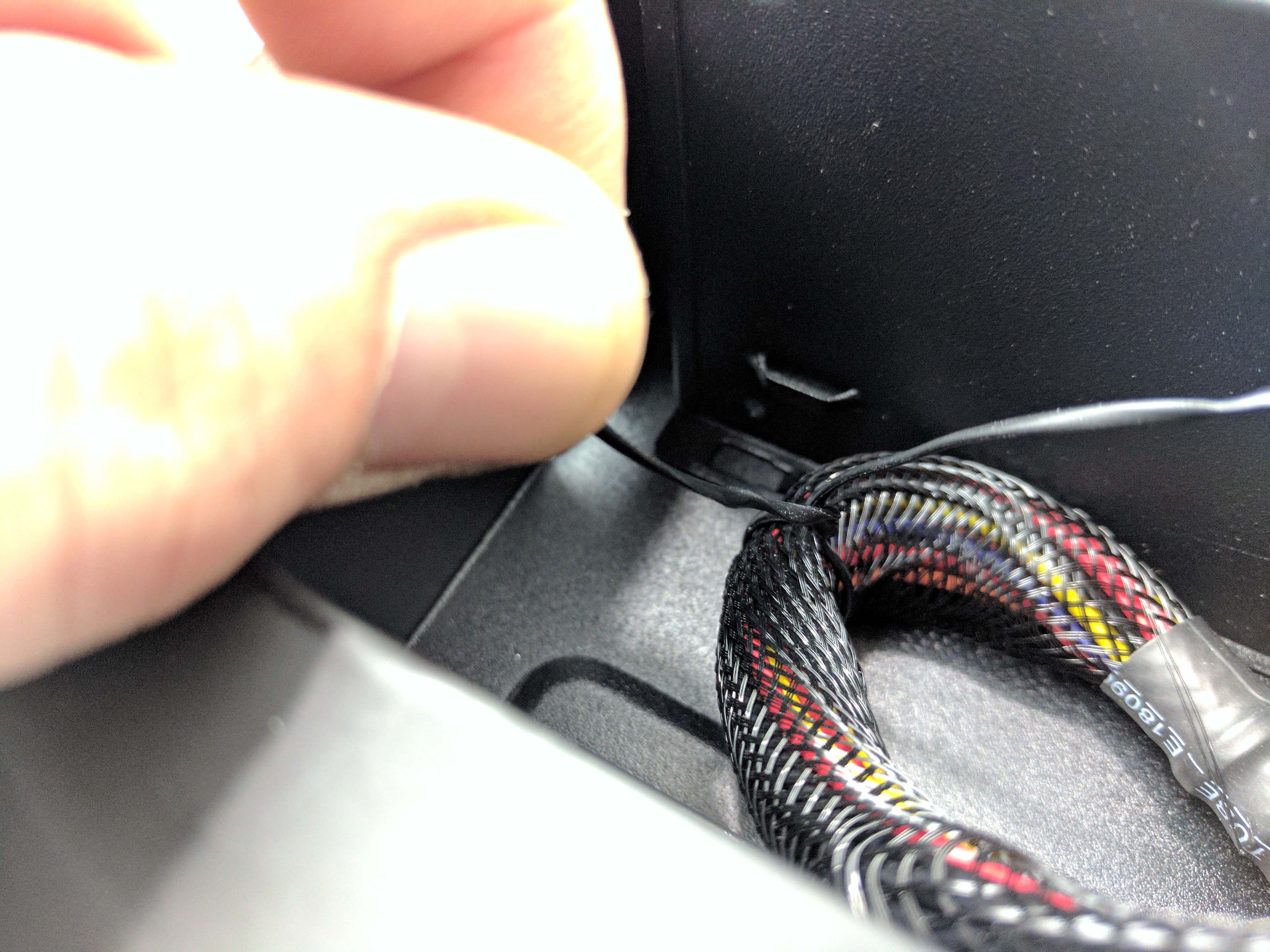
Secure the main ATX power cable using a tie wrap through the loop in the chassis near the 2.5” drive bay (it tends to pop up if you don’t), as seen in slide 3 above.
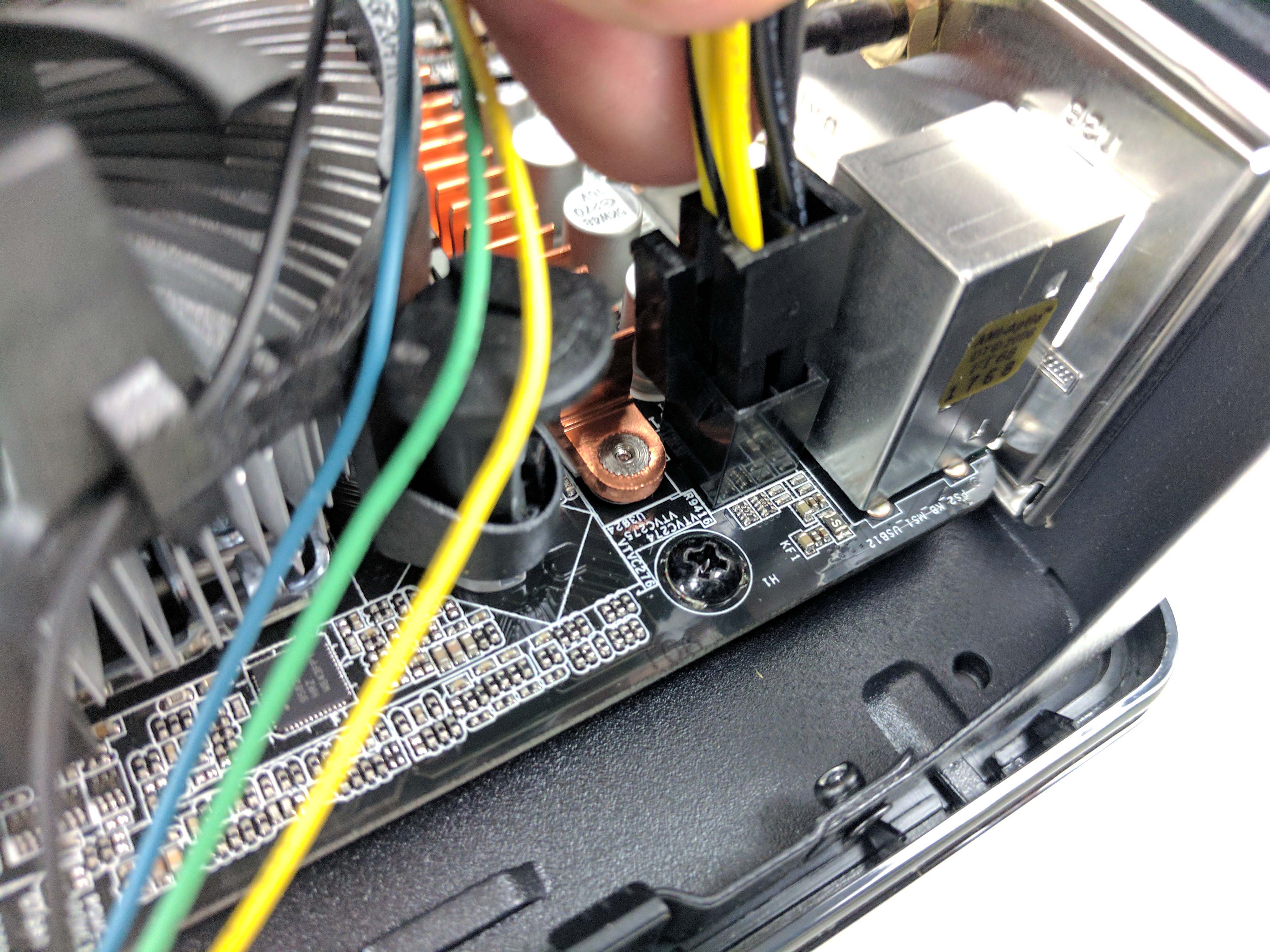
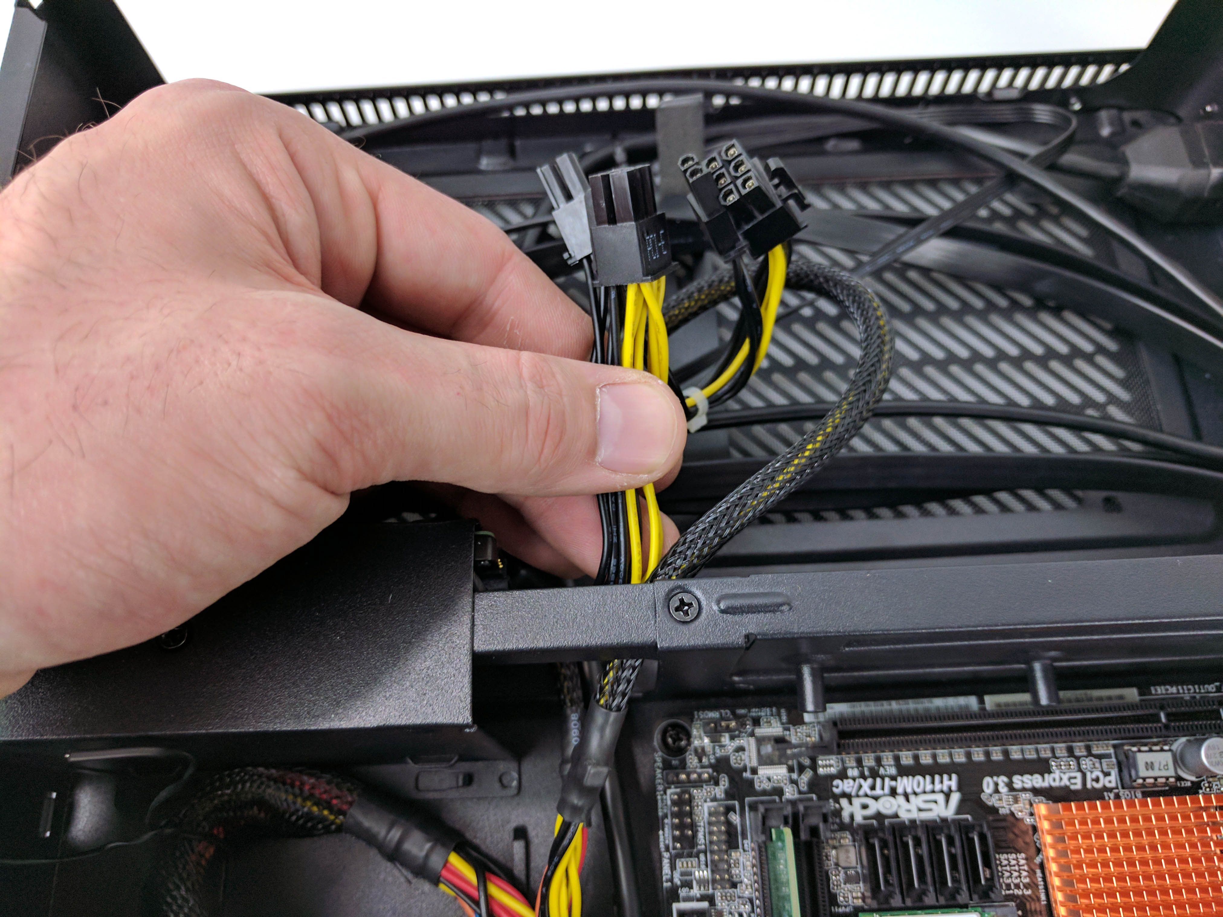
Connect the 4-pin CPU cable to the port on the motherboard (see slide 4 above) and run the cable as best you can around the memory and ATX power plug.
As you bend the PSU cables to make them fit within the constraints of the chassis (it’s not a case that exactly allows for meticulous cable management), you may also notice that the power supply and its internal cage feel slightly loose, but this is normal, and it will become stable when you reattach the case panels and screw them down.
To make room for the rest of the cables, feed the power supply’s PCIe and SATA power cables to the GPU bay of the chassis (see slide 7 above).
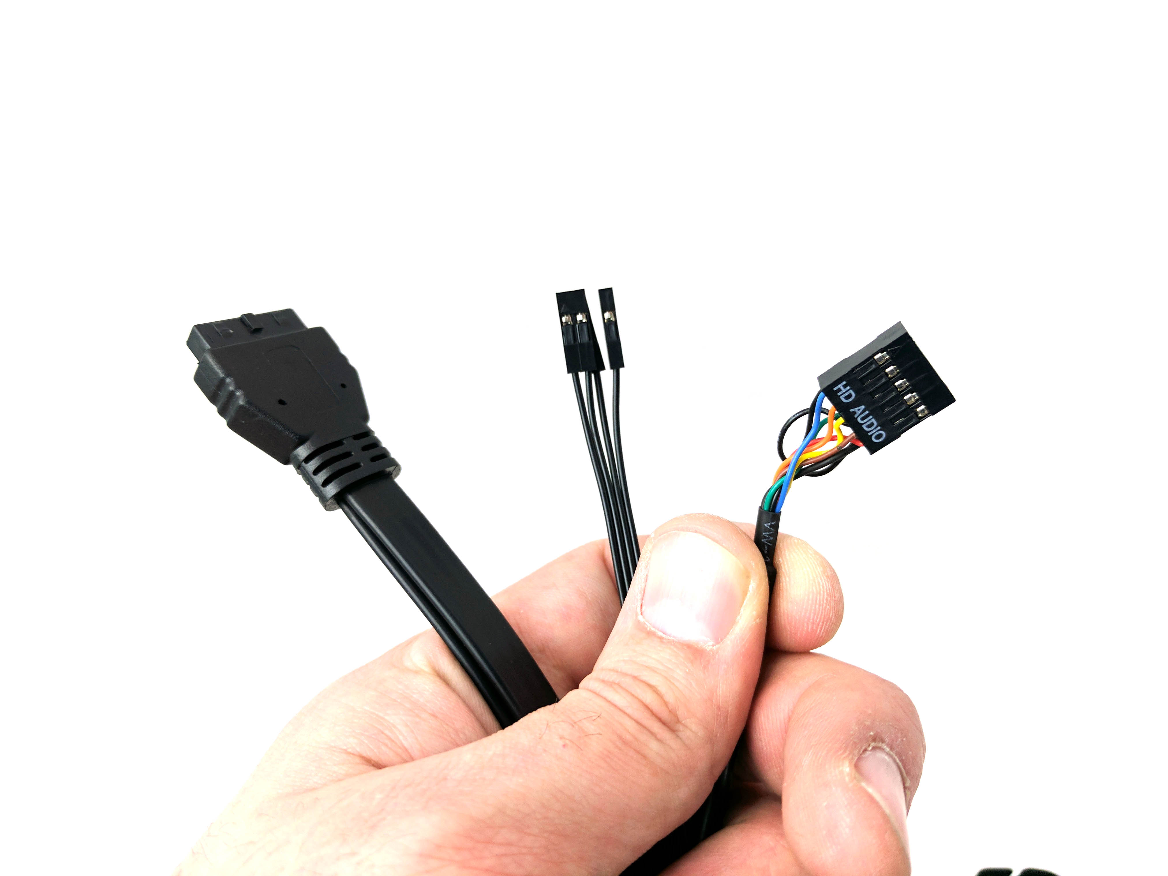
Feed the USB 3.0, audio, and front panel wiring from that bay to the main chamber (as shown in the last two pictures in the album above).
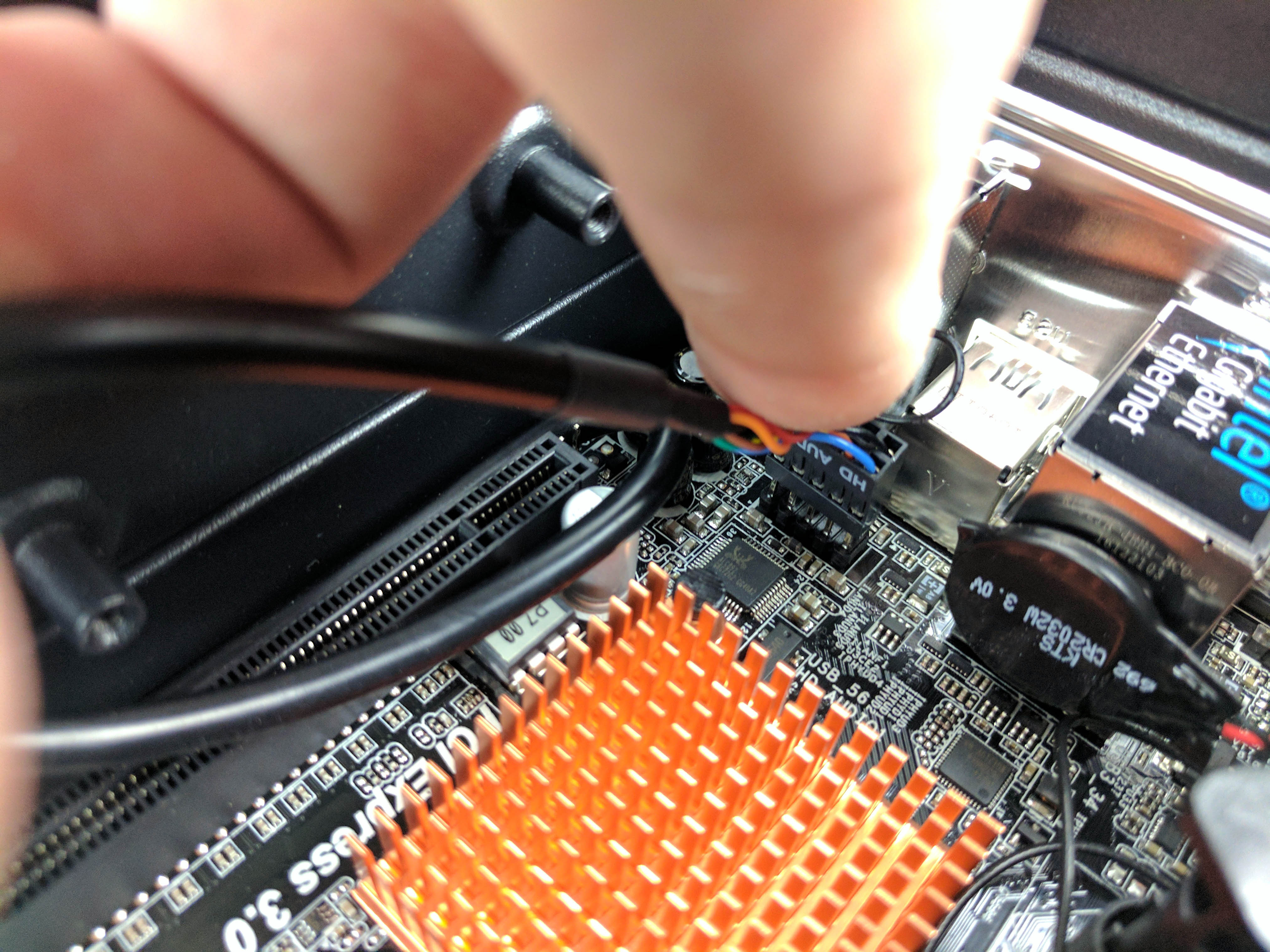
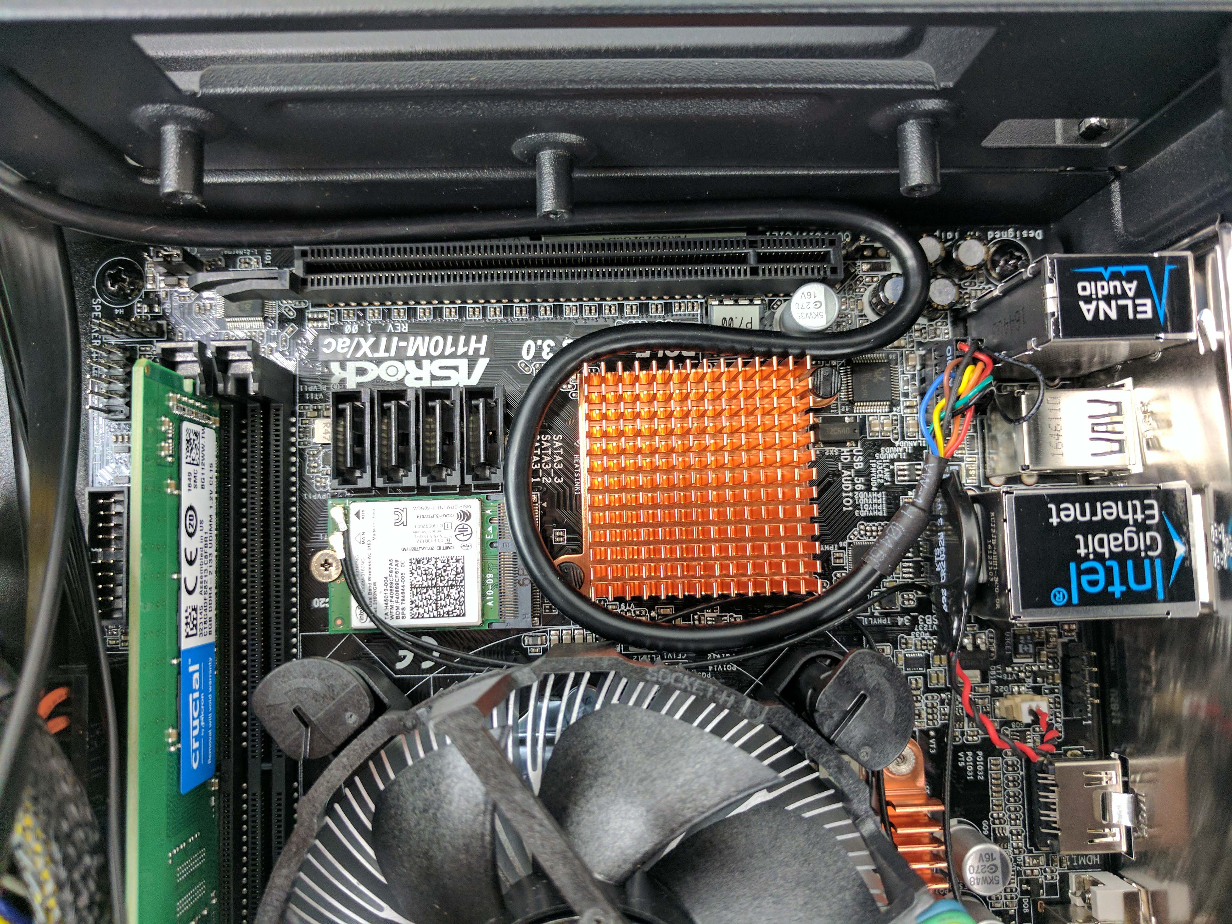
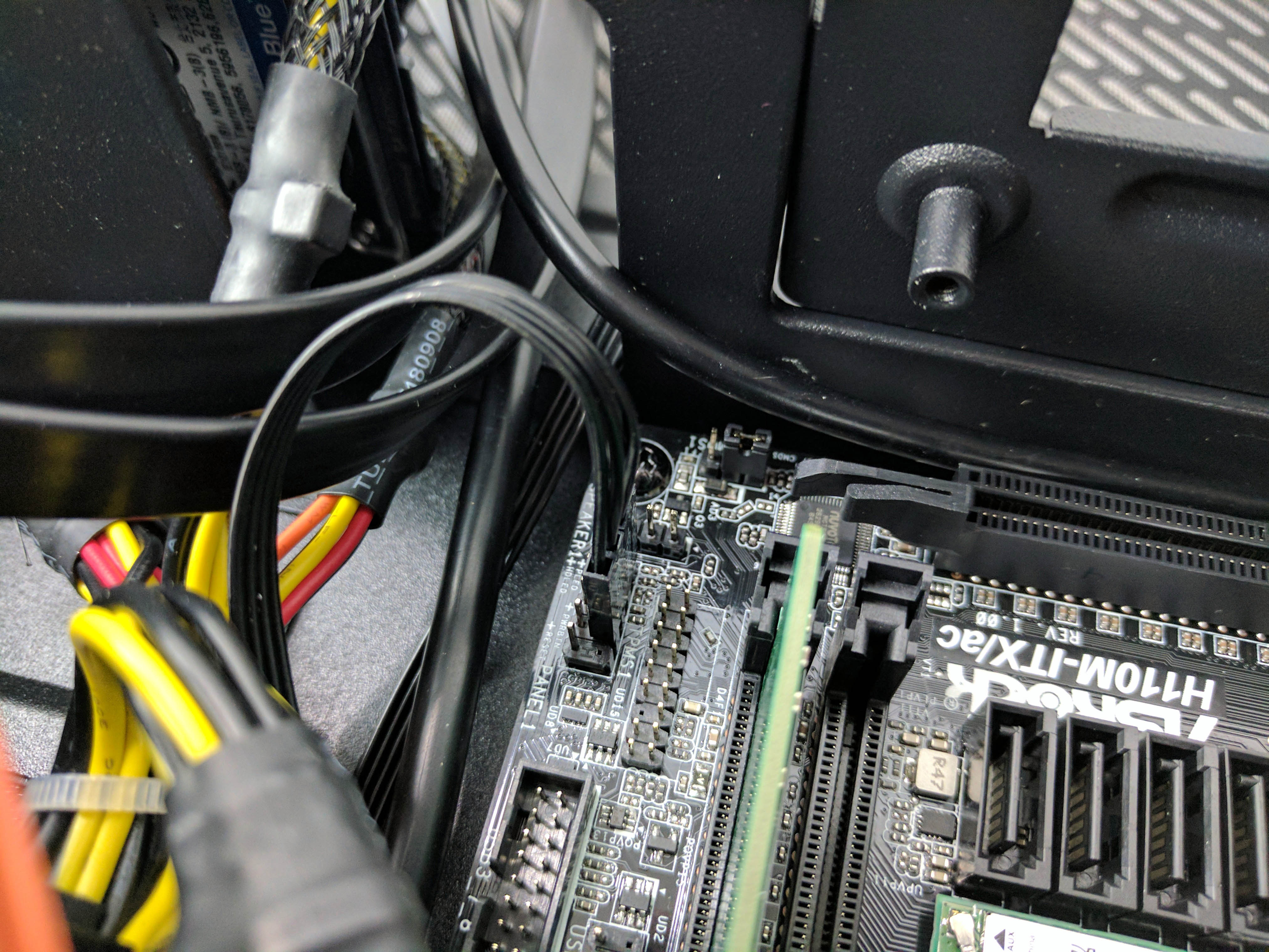
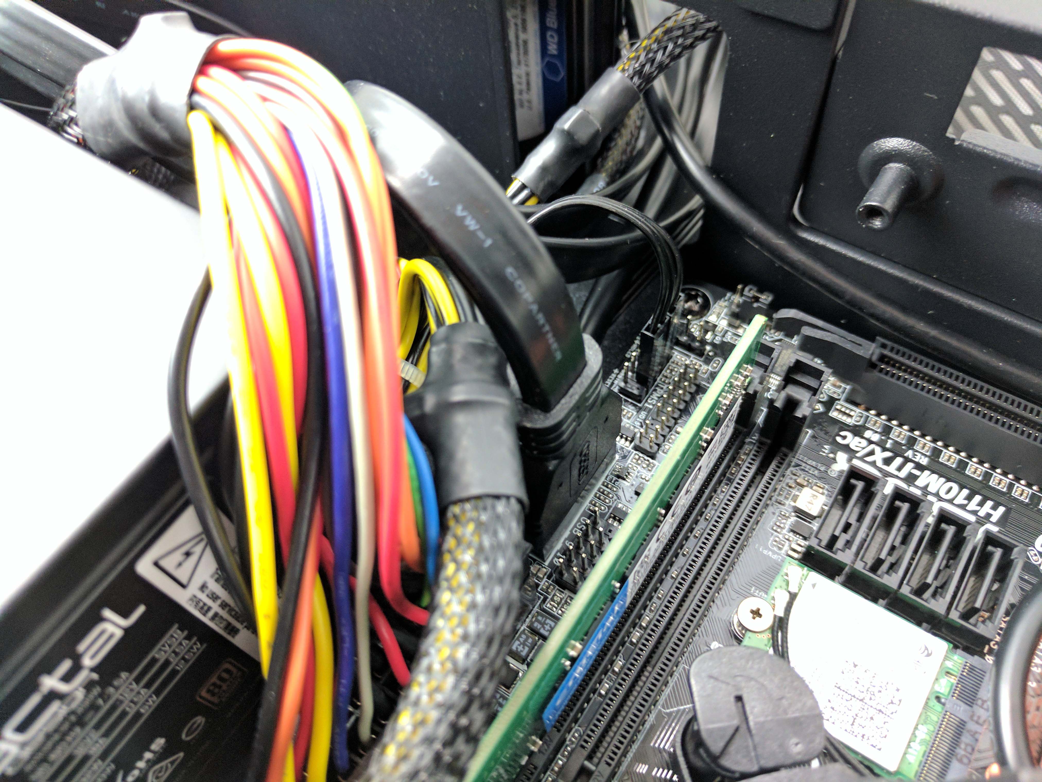
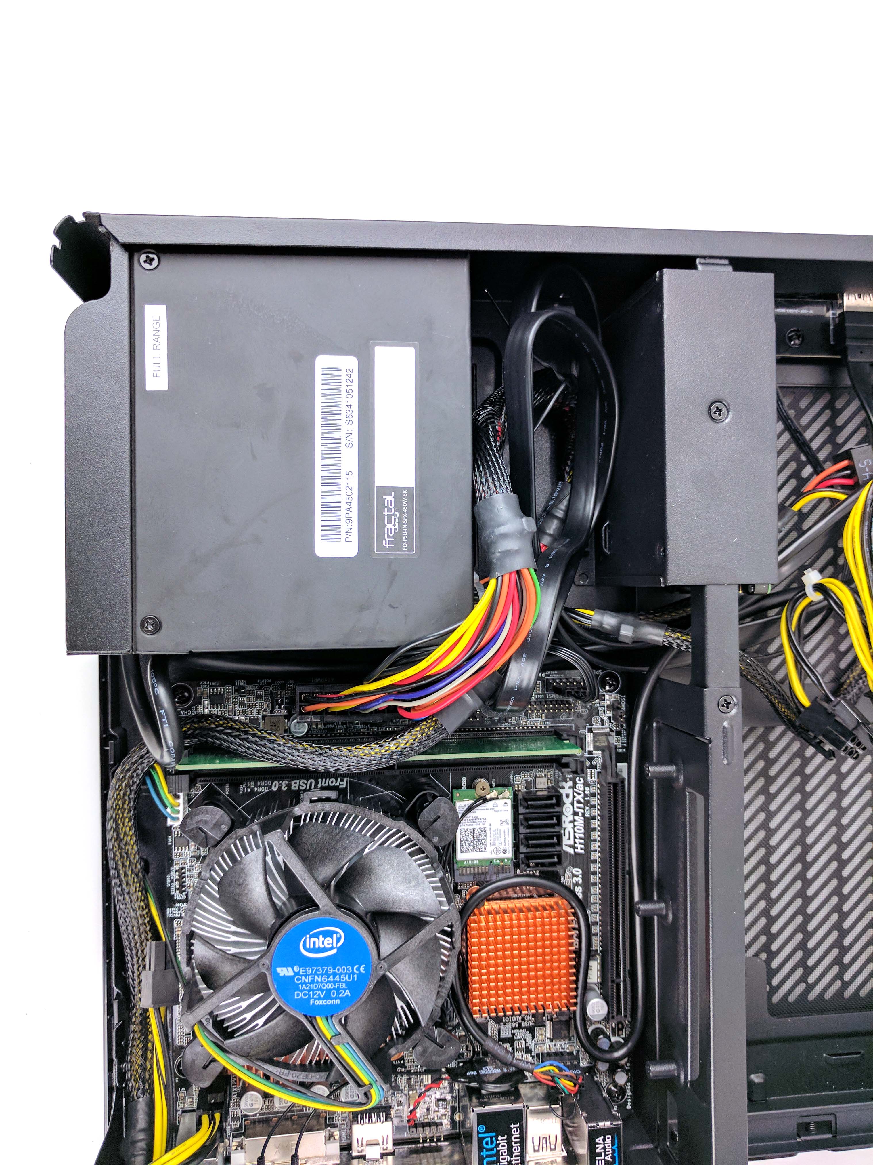
Run the audio cable along the edge of the motherboard (between the PCIe lane and the chassis wall), and plug it in (see first slide directly above). The excess cable can be looped snugly around the orange PCH heatsink.
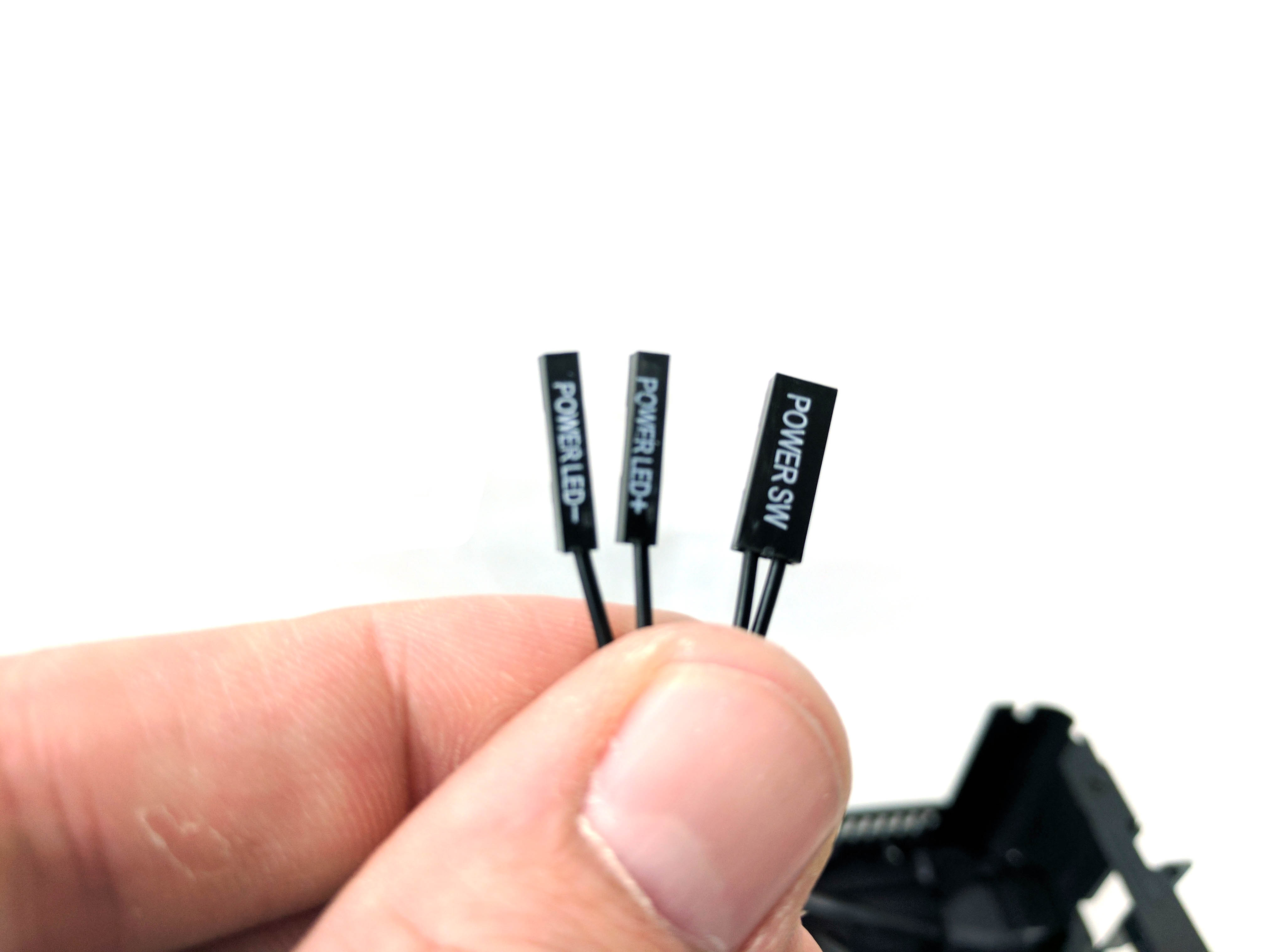
Connect the front panel I/O leads directly to the motherboard (see slide 4 above). There are only three plugs (the Power switch and Power LED + and - leads), and you should reference the motherboard for the appropriate motherboard pins, which are located in the corner of the board near the PSU (next to the front panel USB 3.0 connector).
Attach the front panel USB 3.0 cable to the motherboard, being extra careful, as the pins can be quite delicate (we found this out first hand and had to reorder the motherboard). Tuck the excess cable from the USB 3.0 and front panel wires into the area between the PSU and removable 2.5” bay (same as the others).
The Hard Drive
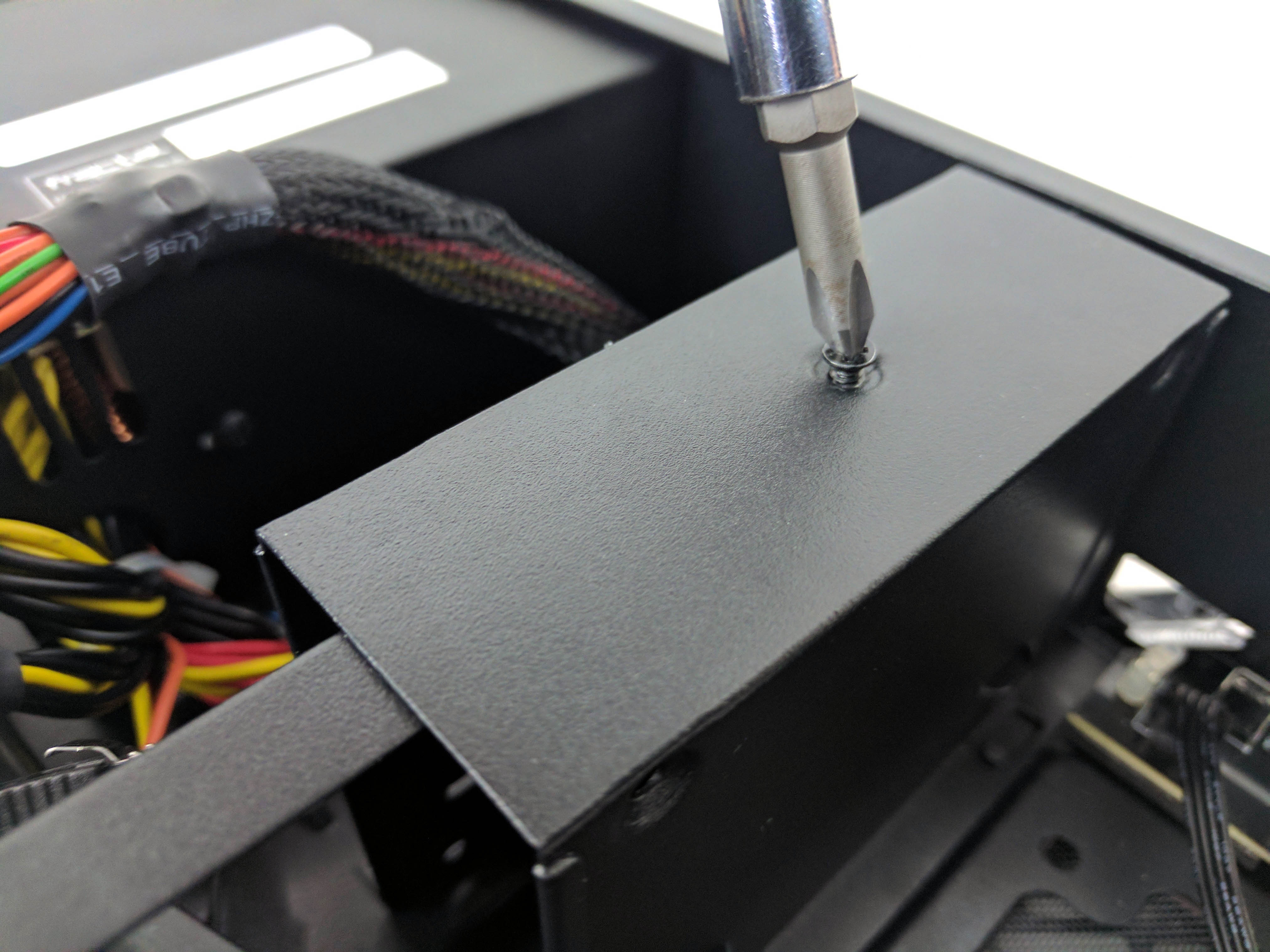
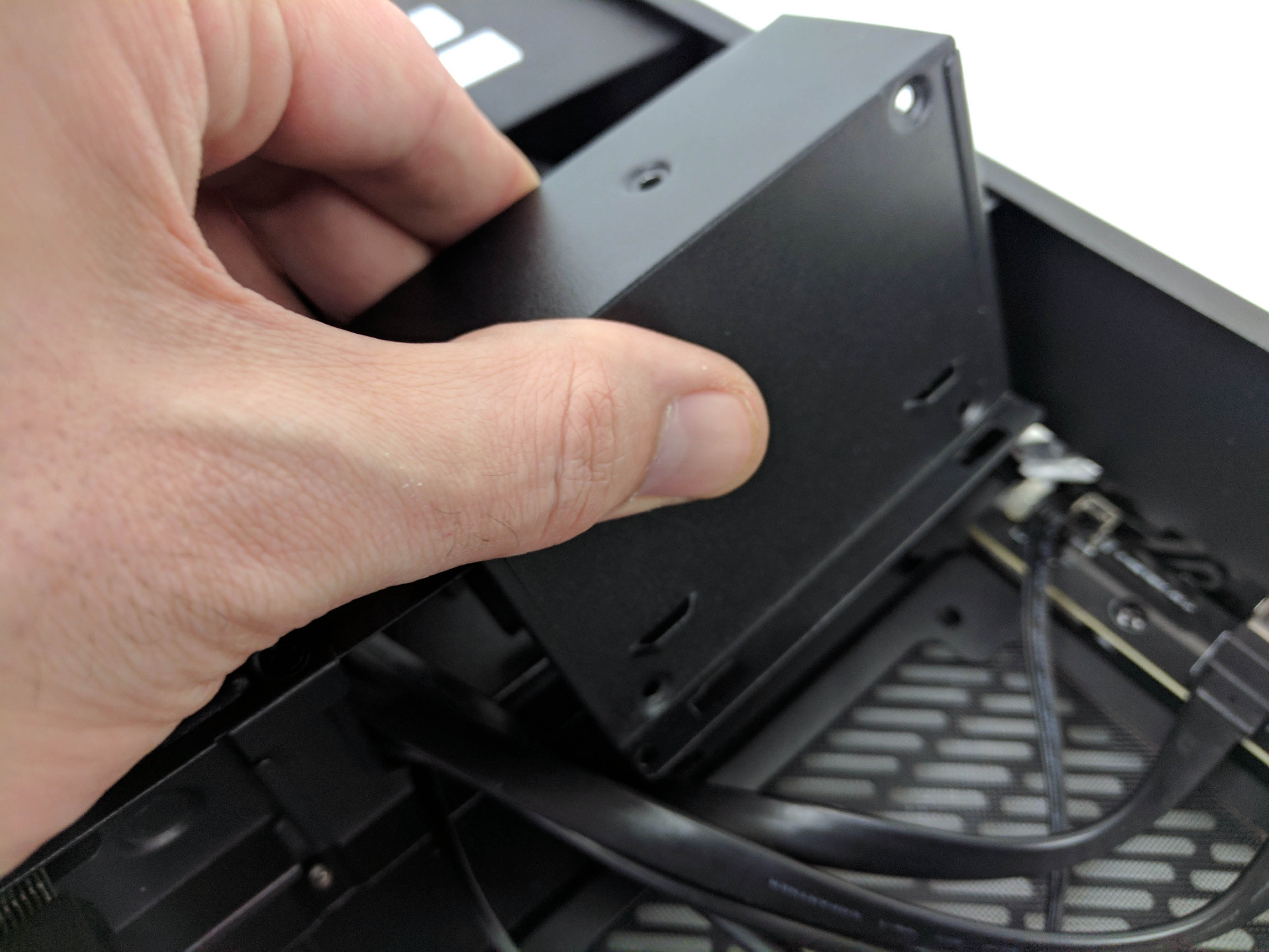
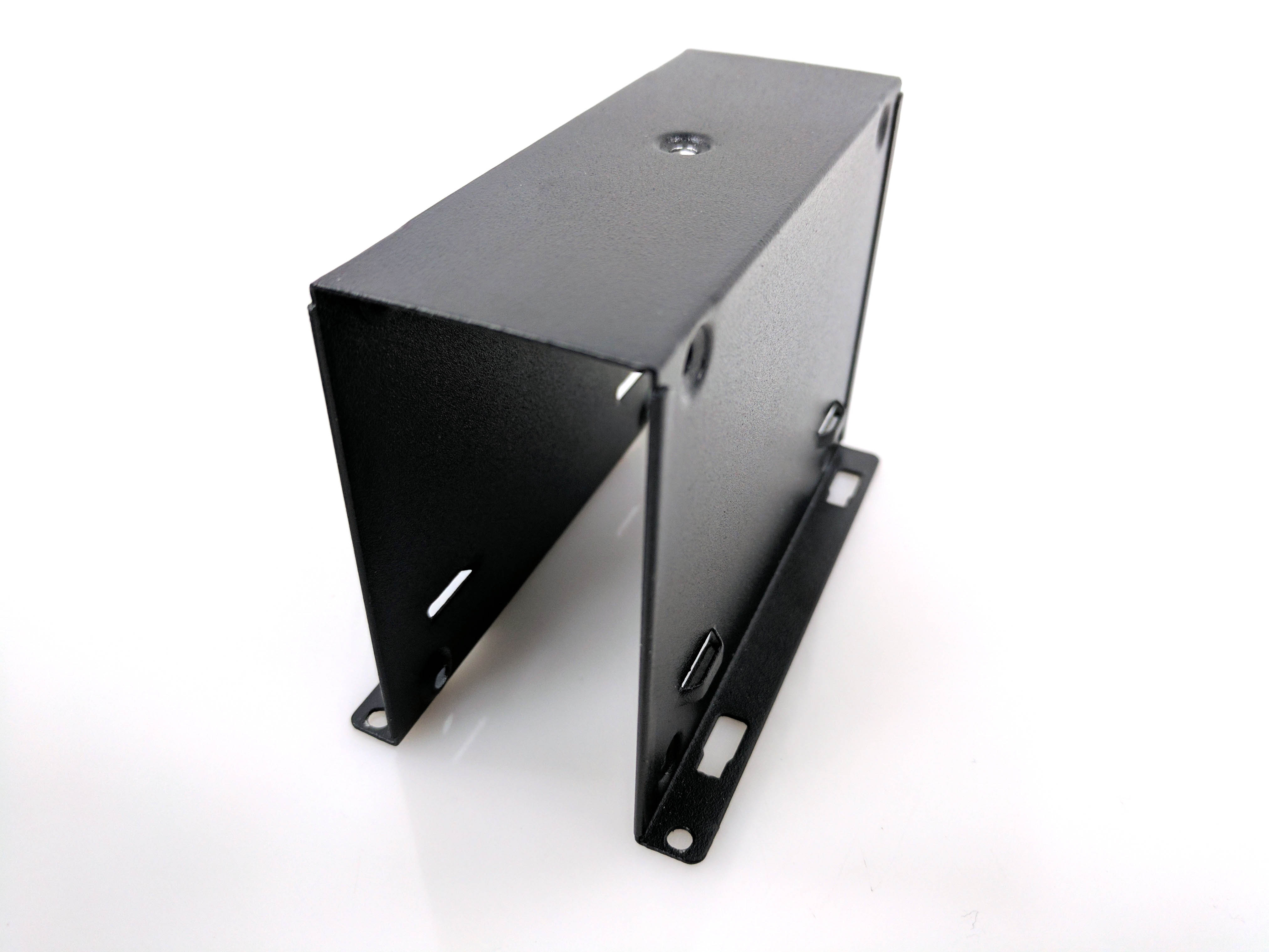
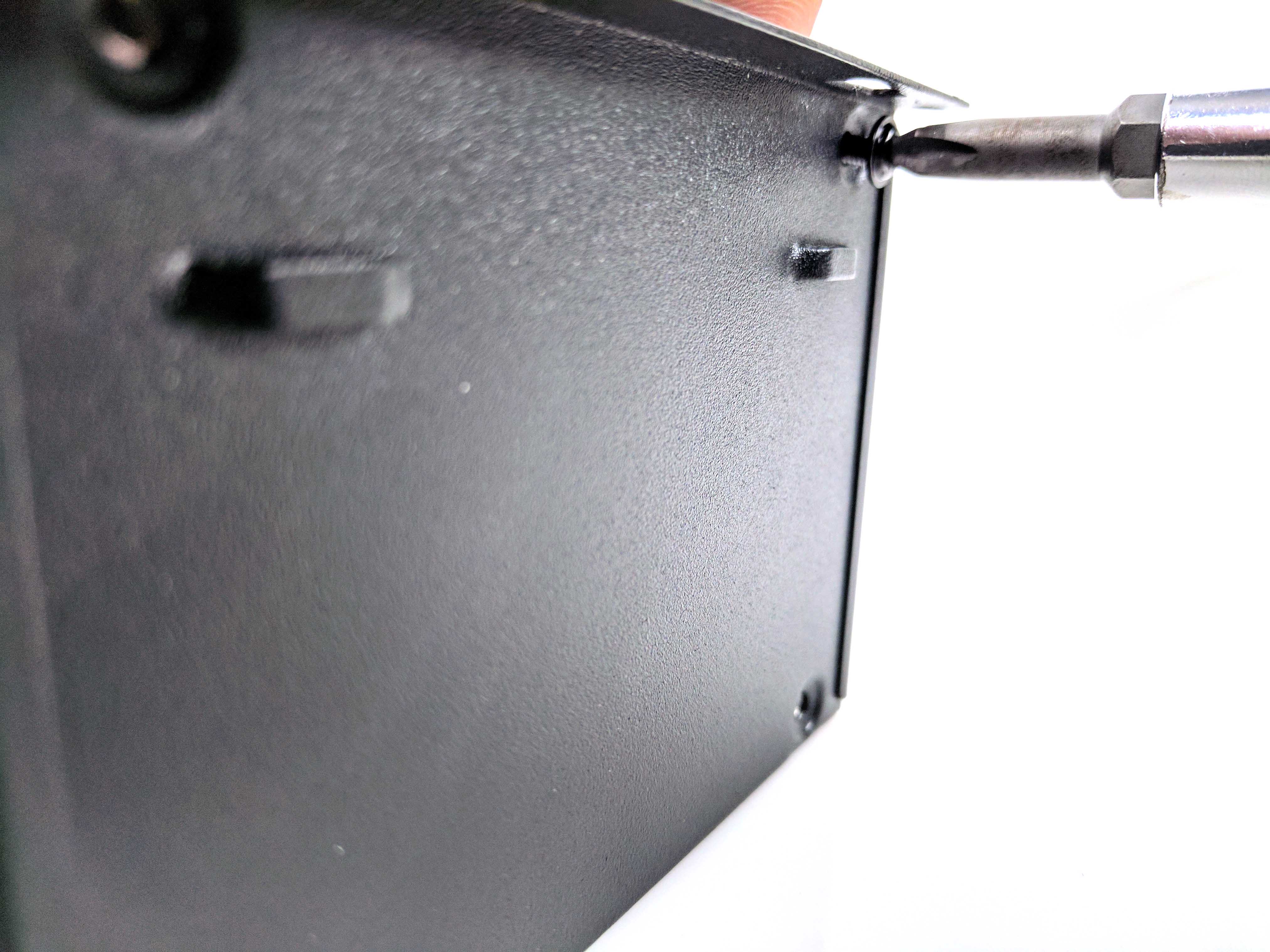
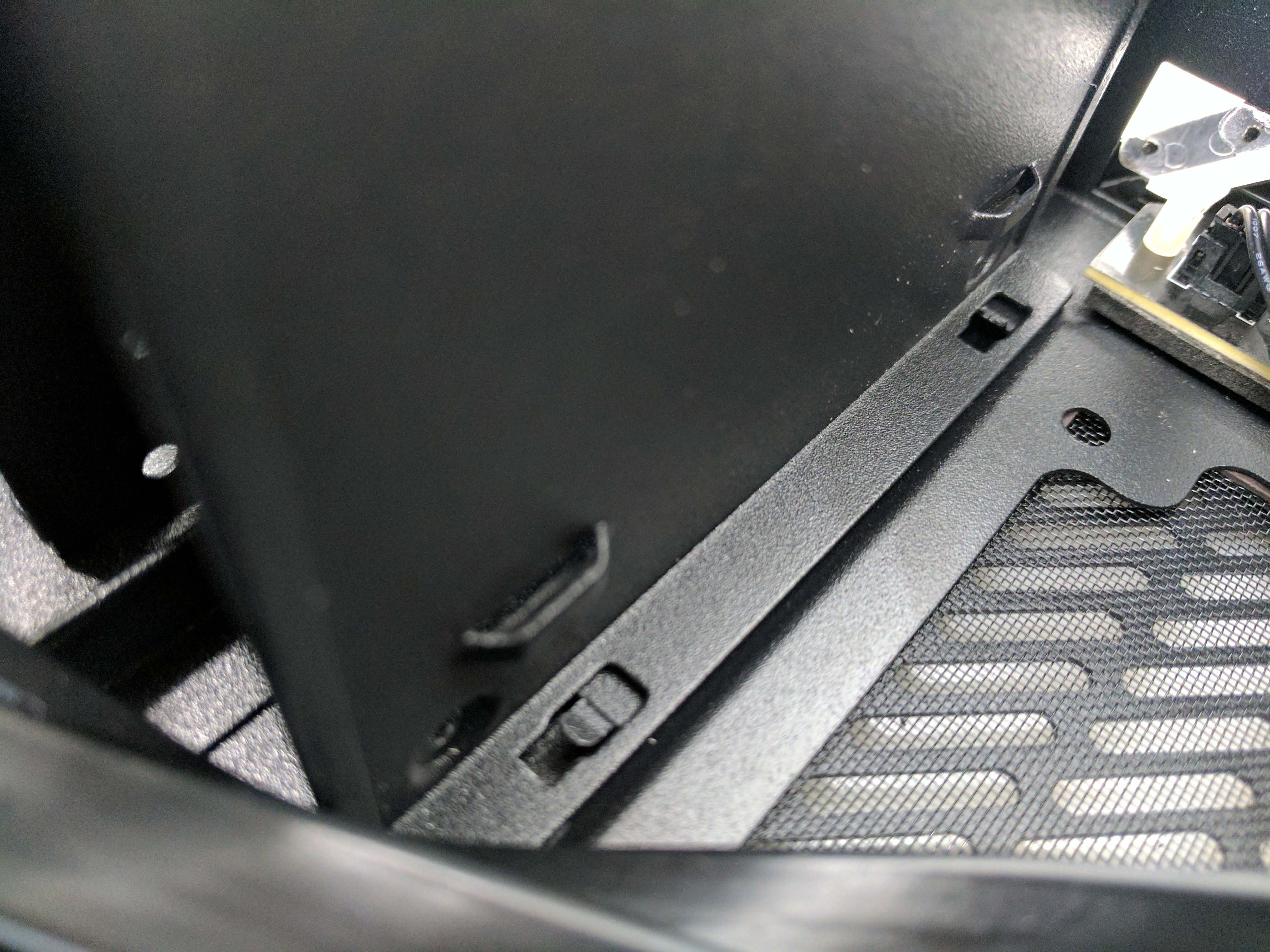
Remove the screw on the top of the drive bay, slide the cage towards the rear of the case, and lift up to remove it from the chassis (see slides 1-3 in the album directly above). Now you can install up to two 2.5” drives without any issue.
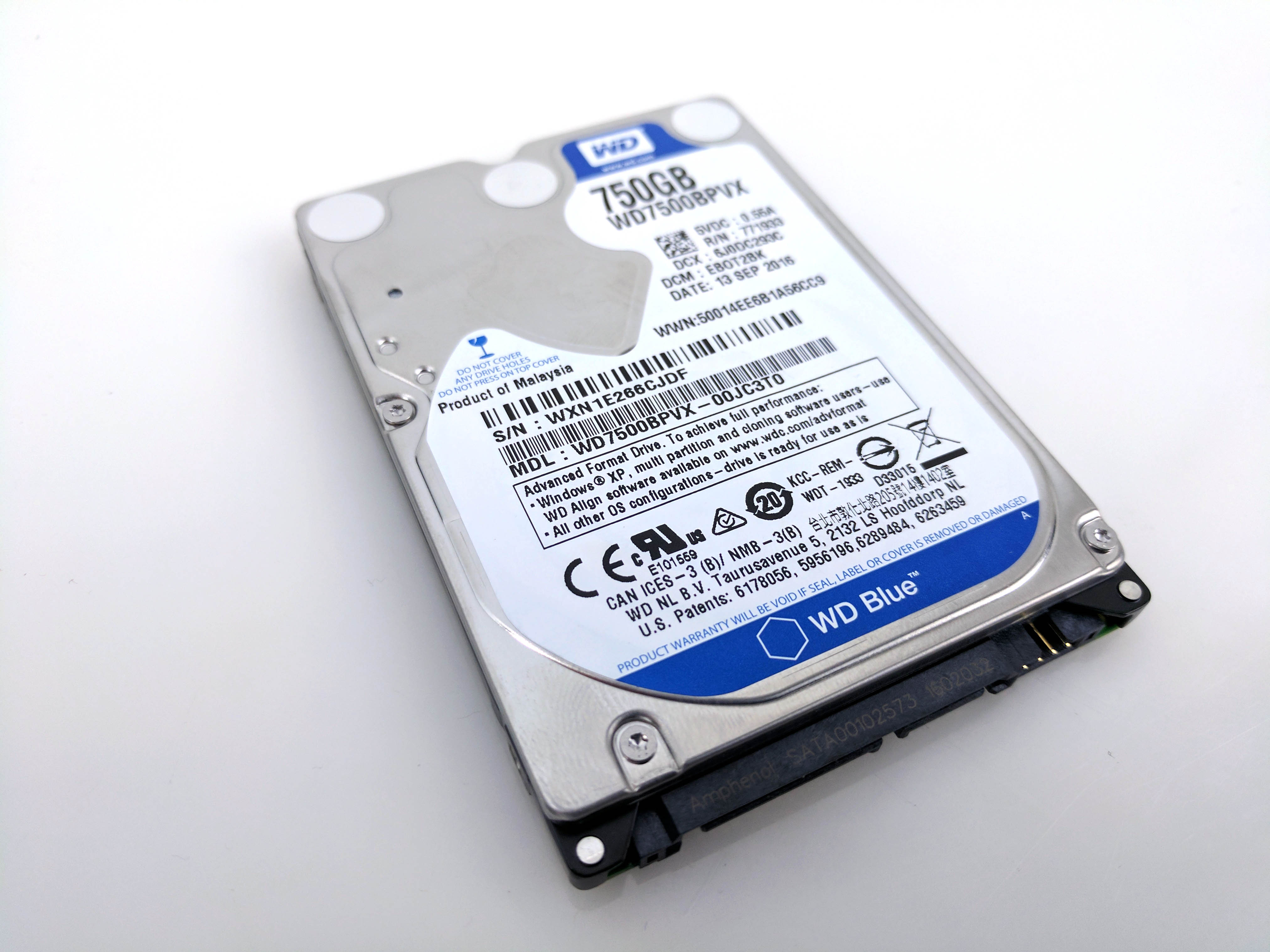
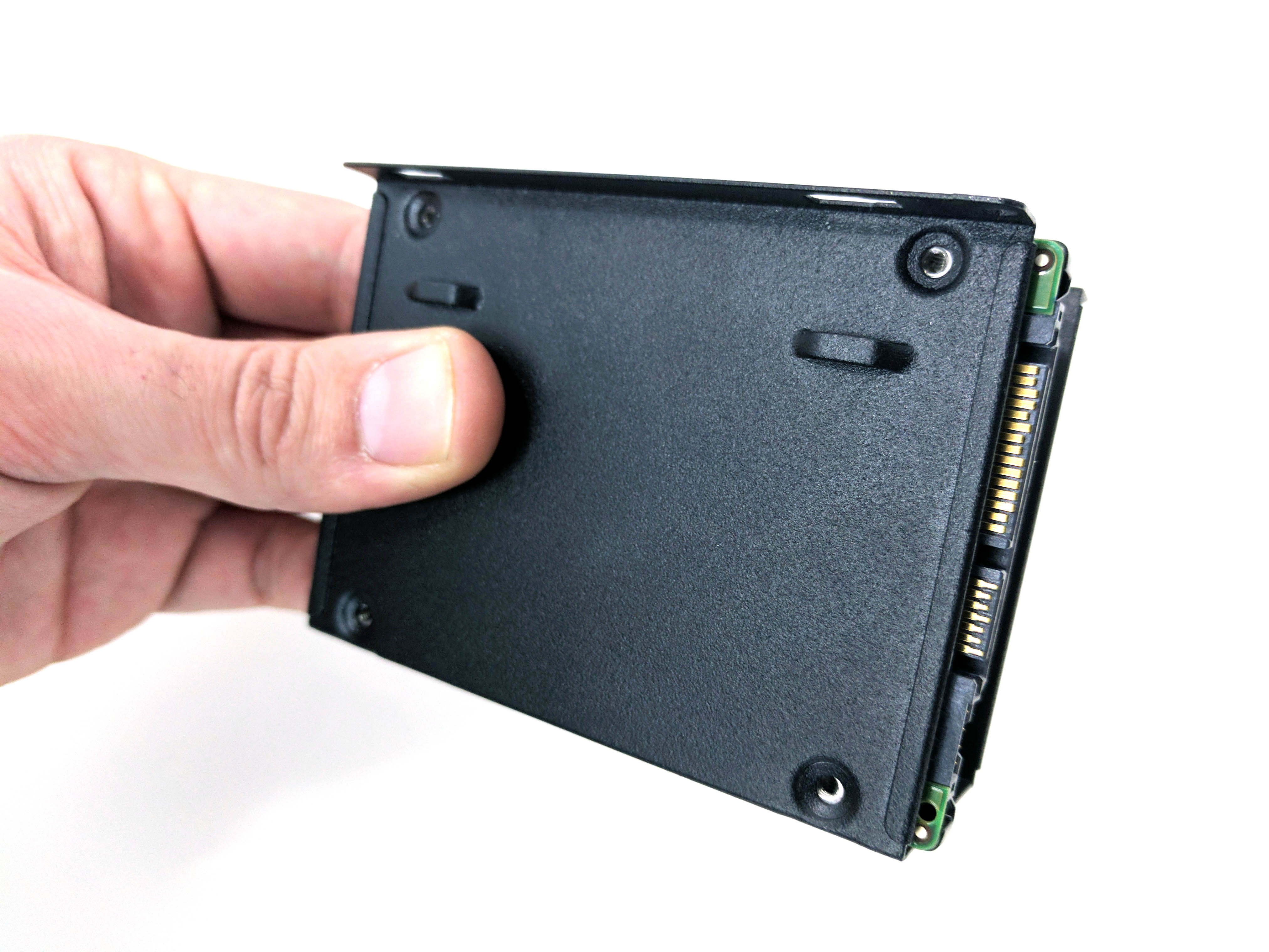
Remove the 750GB HDD from its packaging, slide it into the bay, and line up the four holes on the bottom (GPU chamber) side of the cage to the hard drive (see fifth slide above). Secure the HDD (which should be on the GPU chamber side) with four thin-threaded screws and reattach the cage to the chassis by sliding it back into place by the guides and screwing it back down.
Plug one of the SATA power leads into the 2.5” HDD and tuck the excess away with the rest of the cables. Let the PCIe power cable rest in the corner of the GPU chamber (you can tie it down, it was never needed, but it could prove useful if you upgrade the graphics card down the line). Find a SATA data cable from the motherboard box and connect it between the HDD and motherboard (running it through the hole between the chambers), laying the excess cable in with the rest of the bunched cables by the PSU.
The Graphics Card
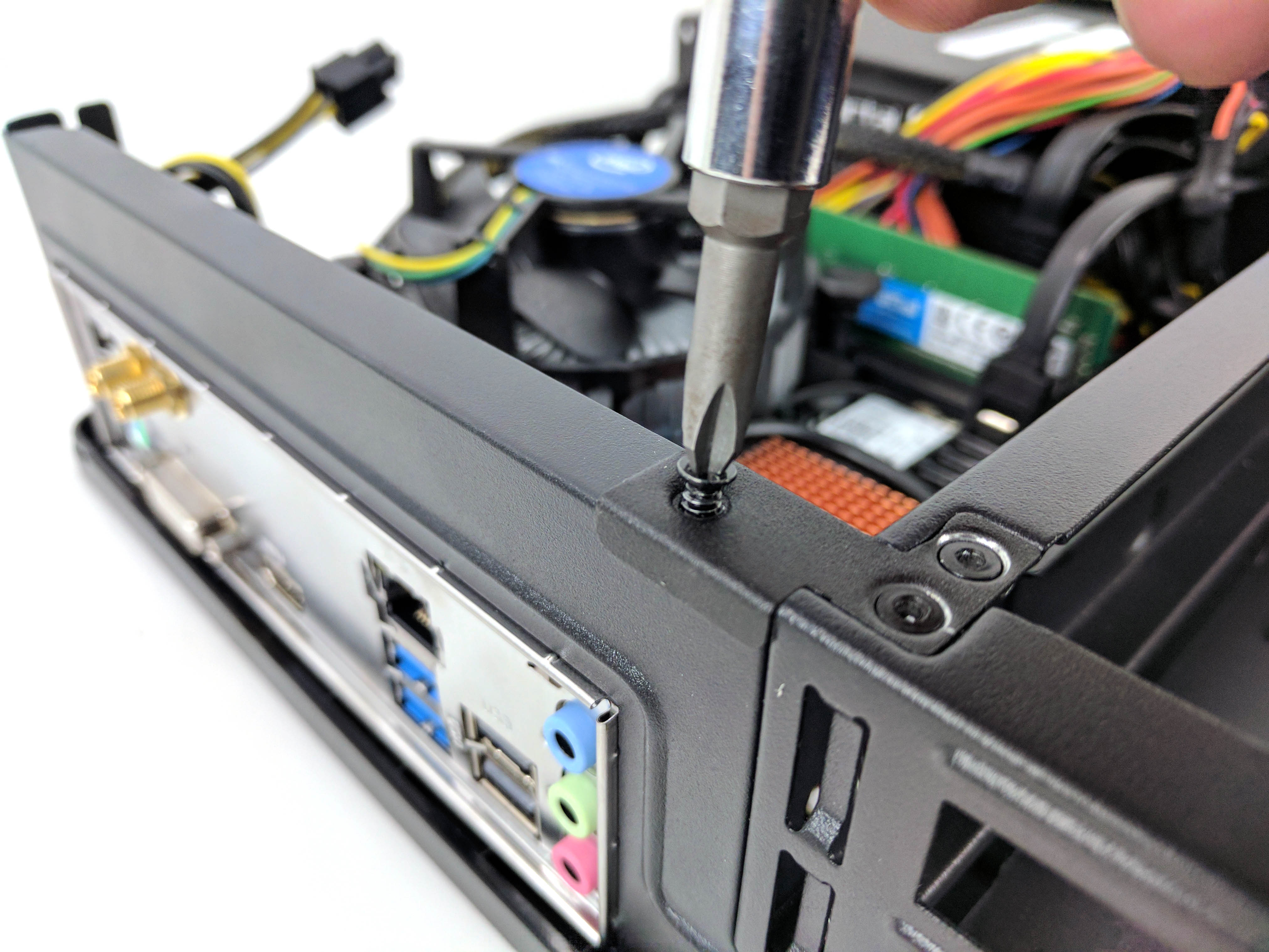
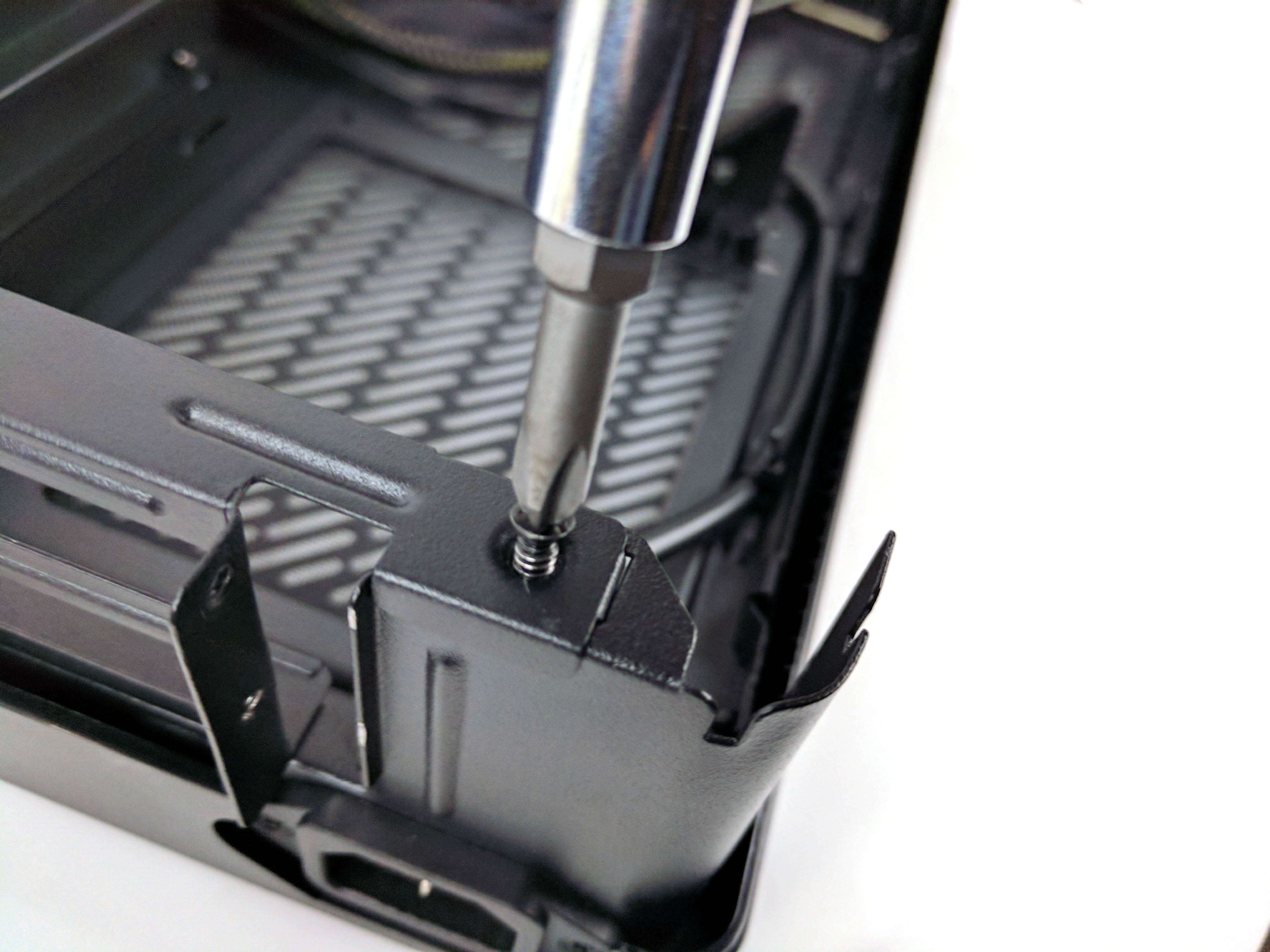
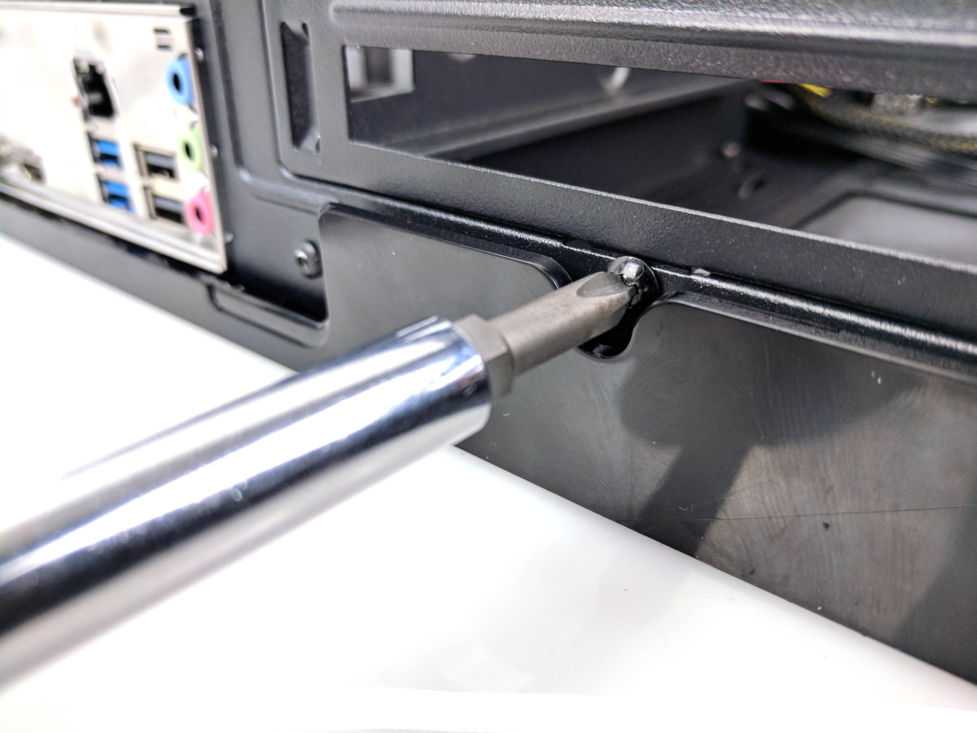
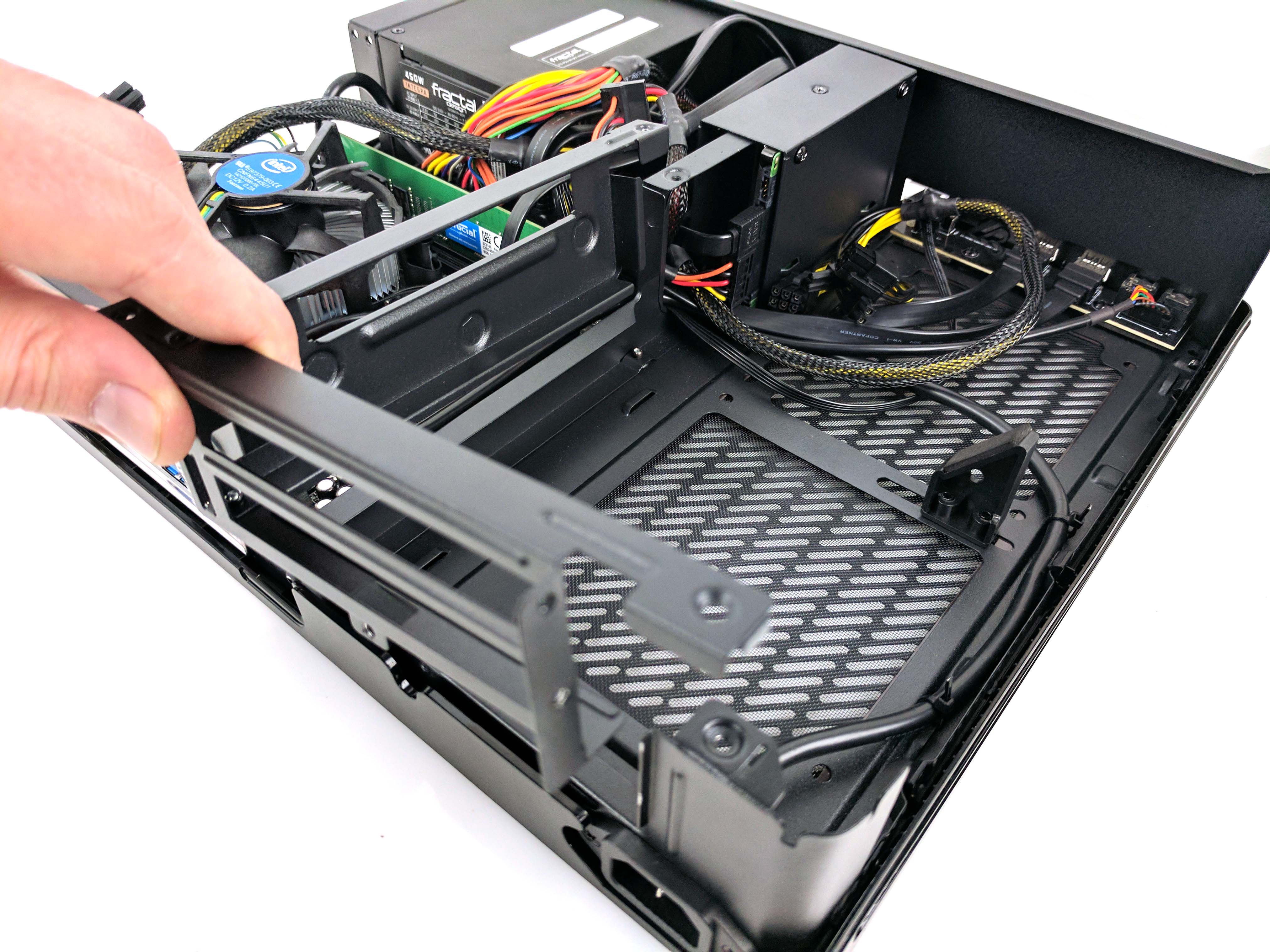
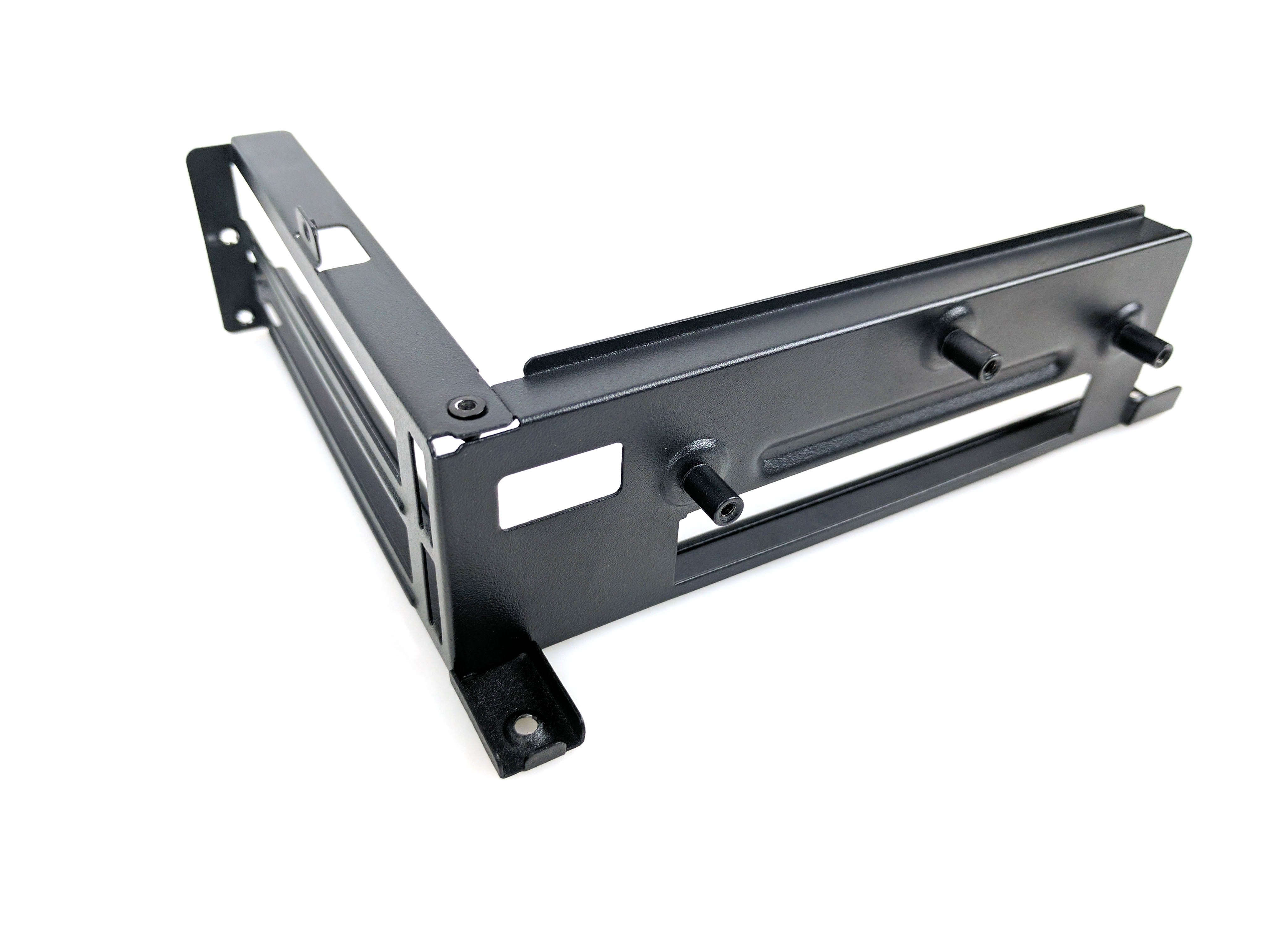
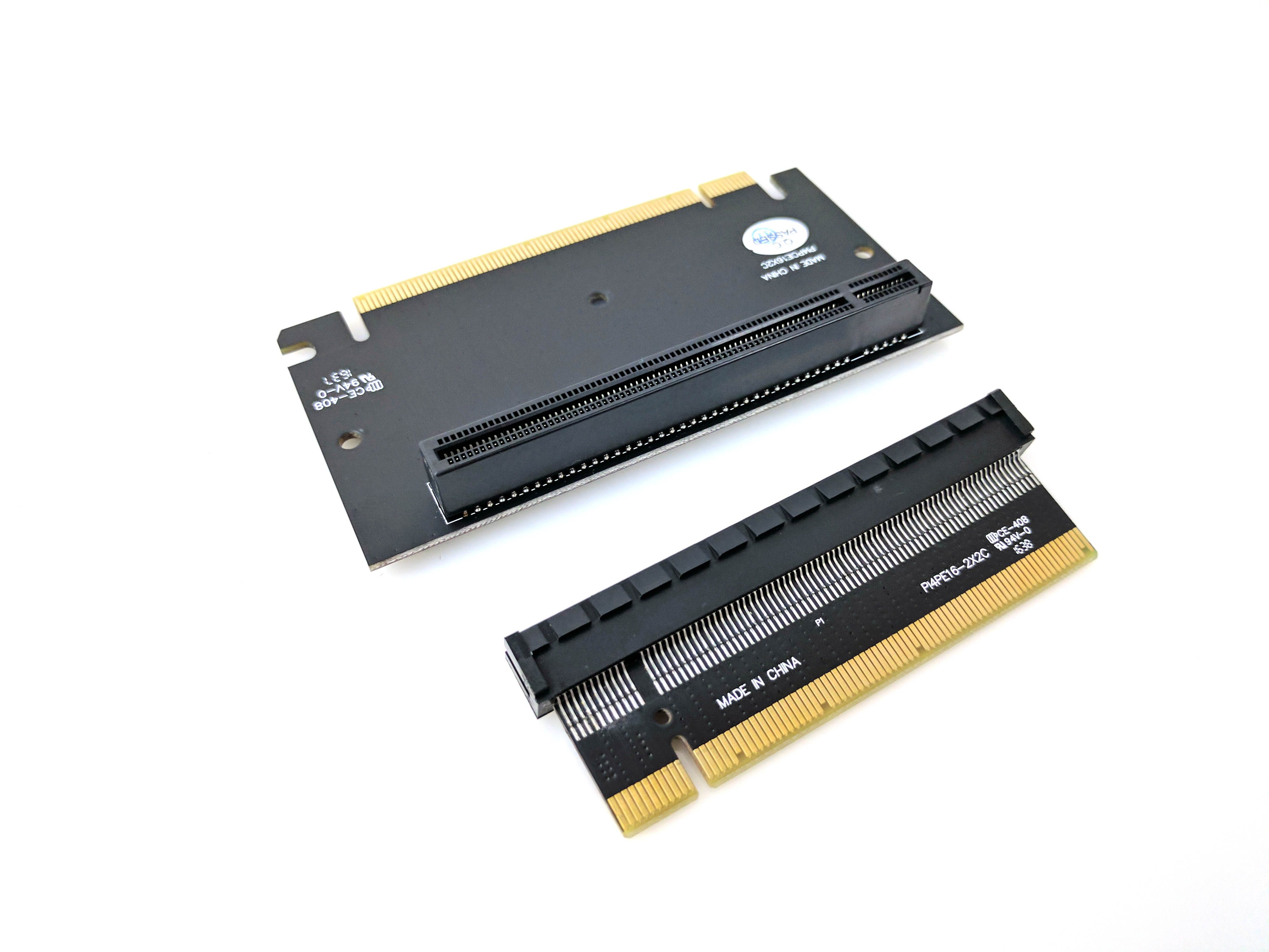
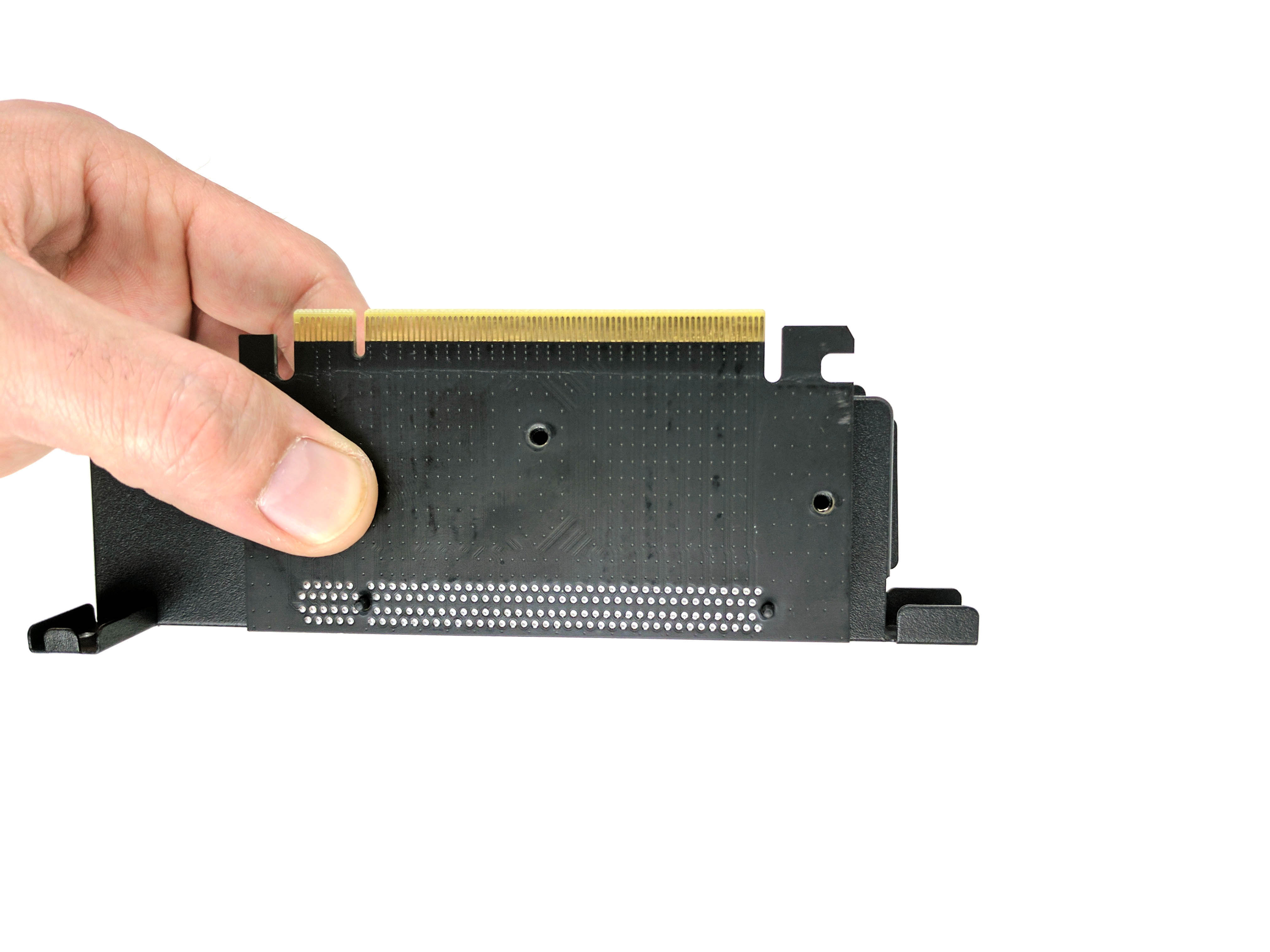
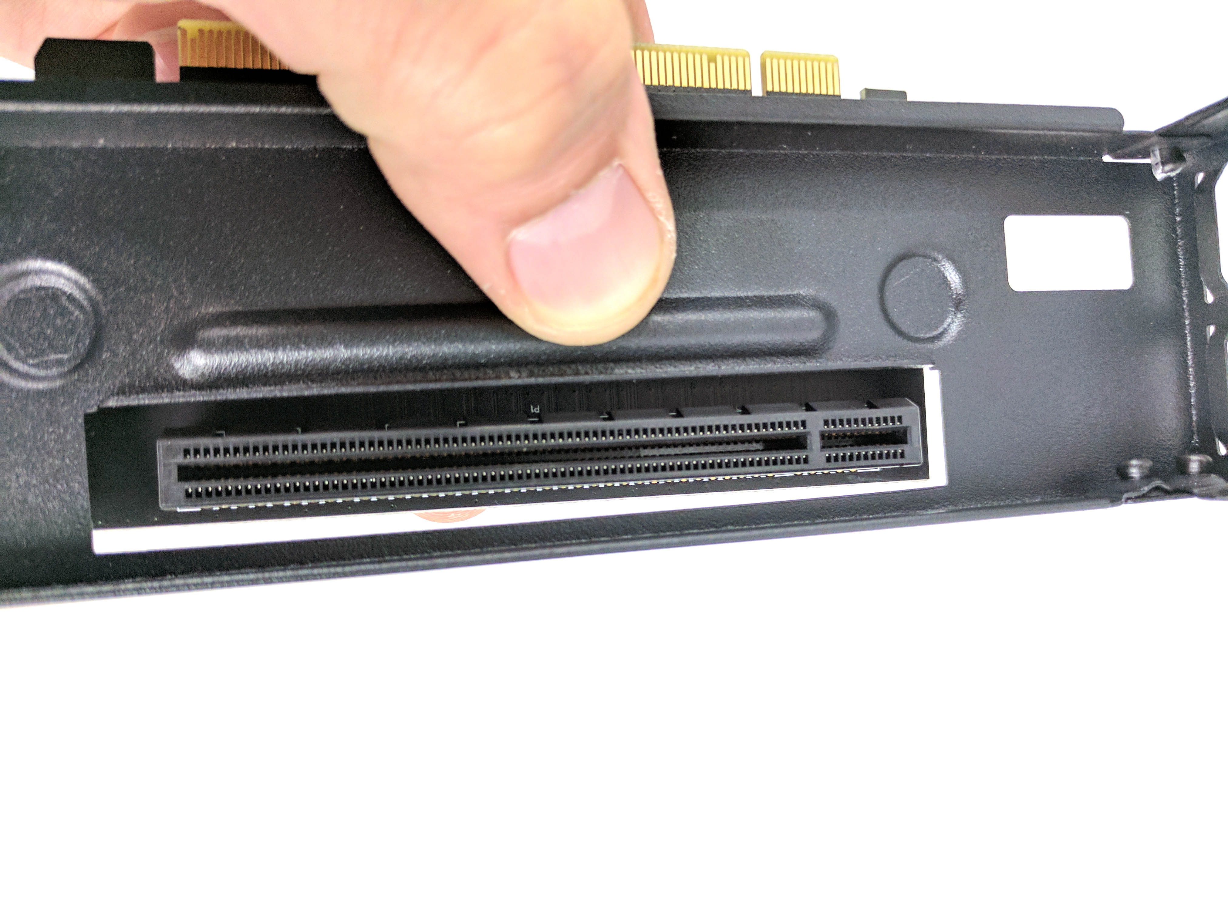
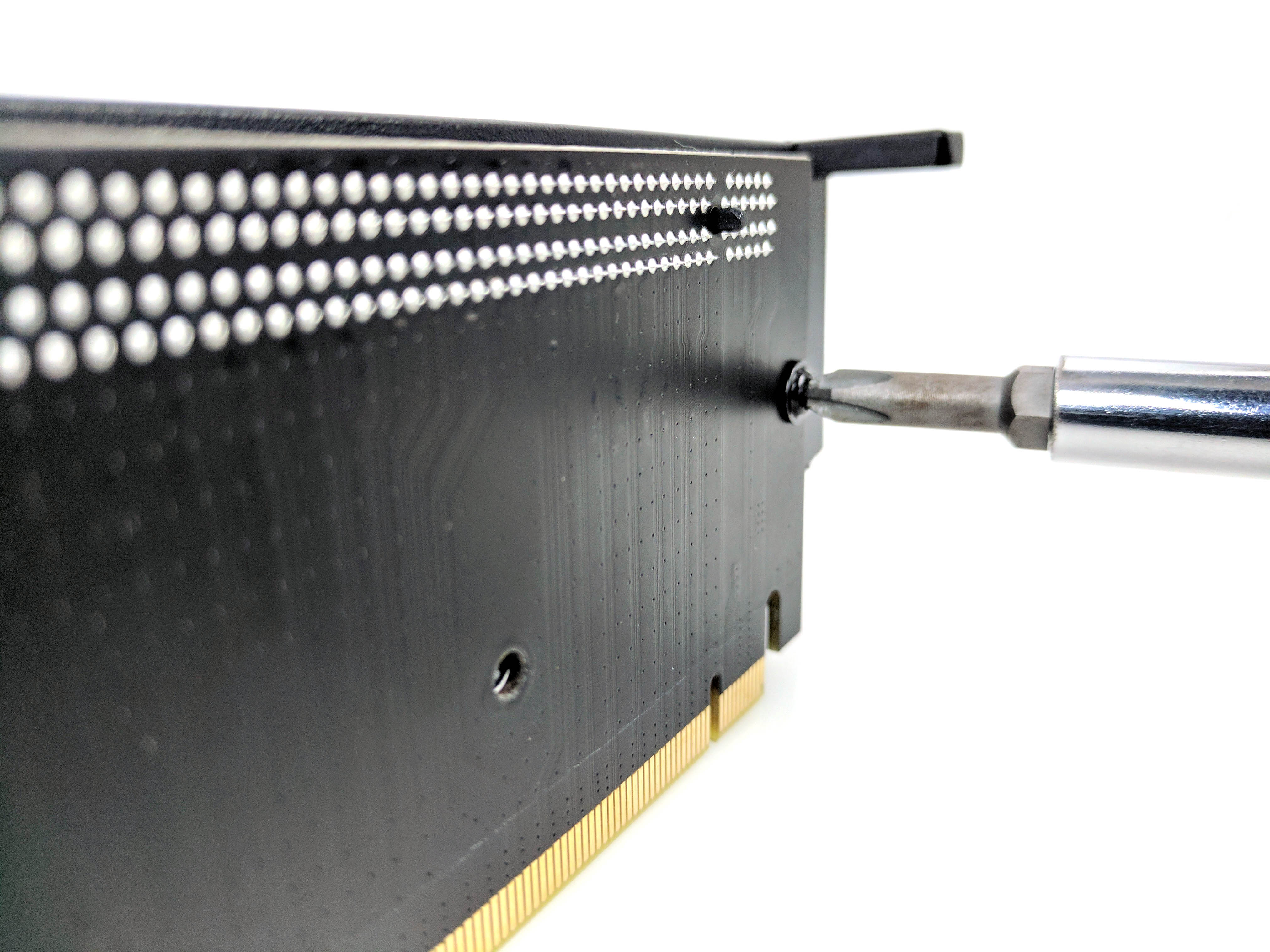
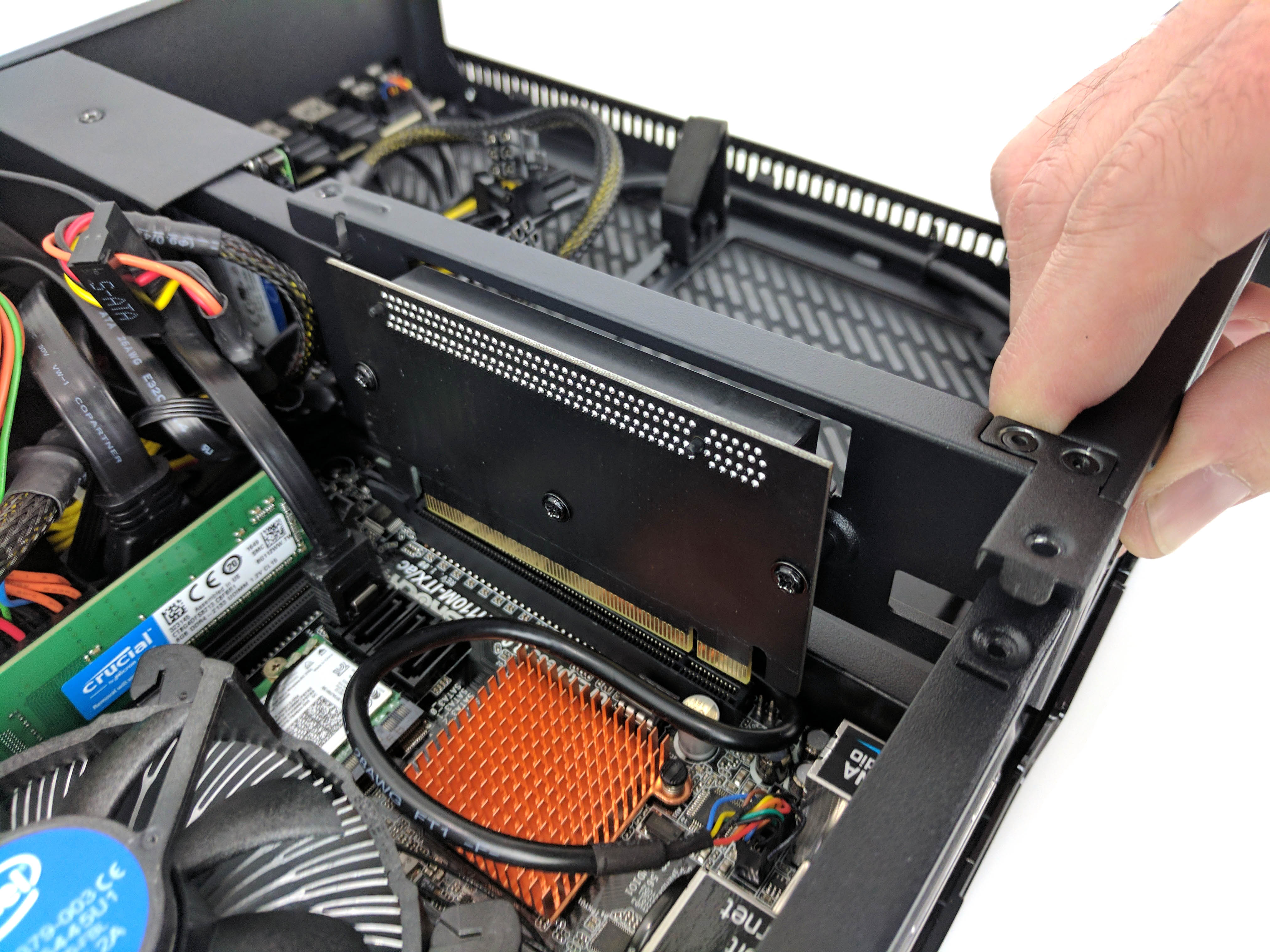
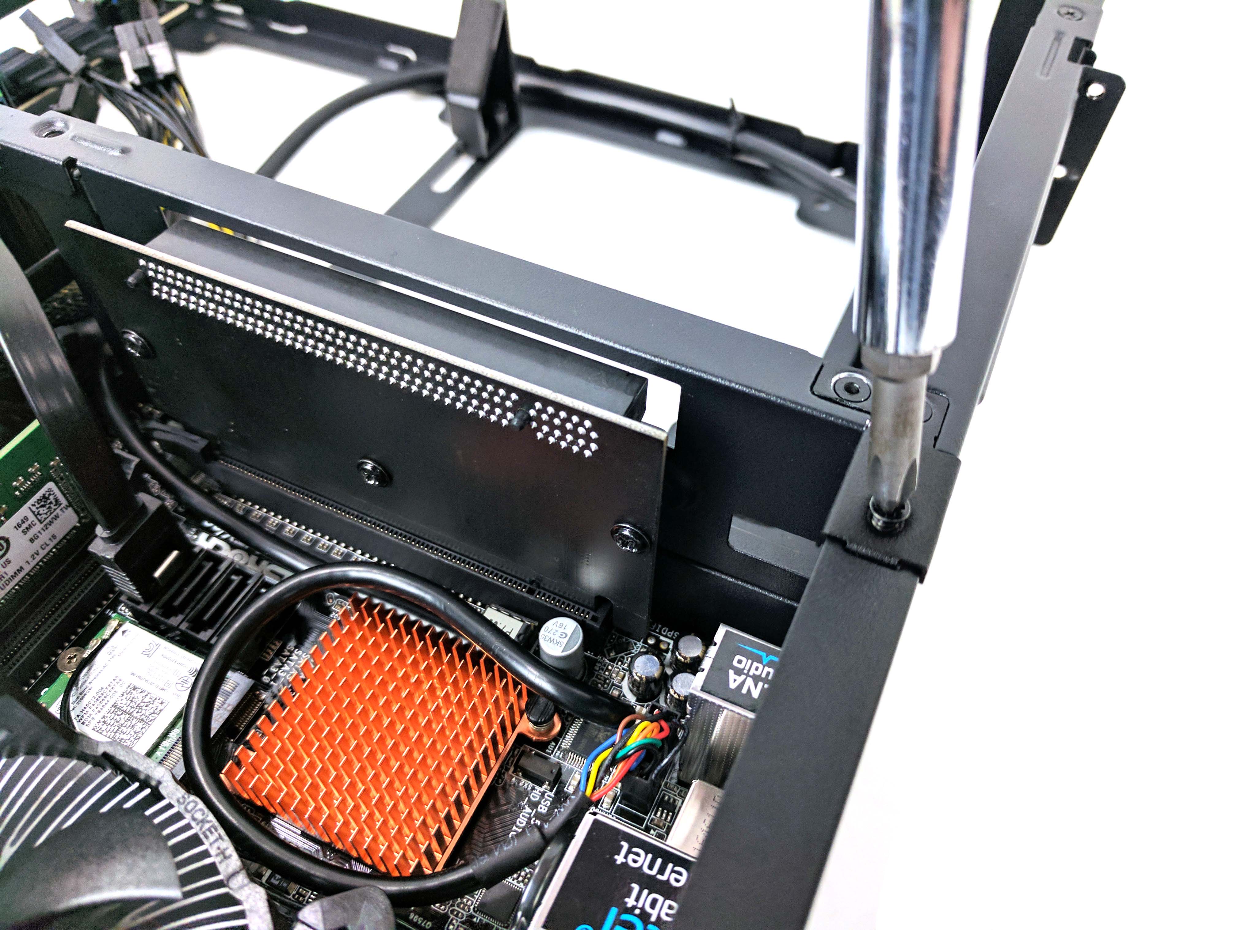
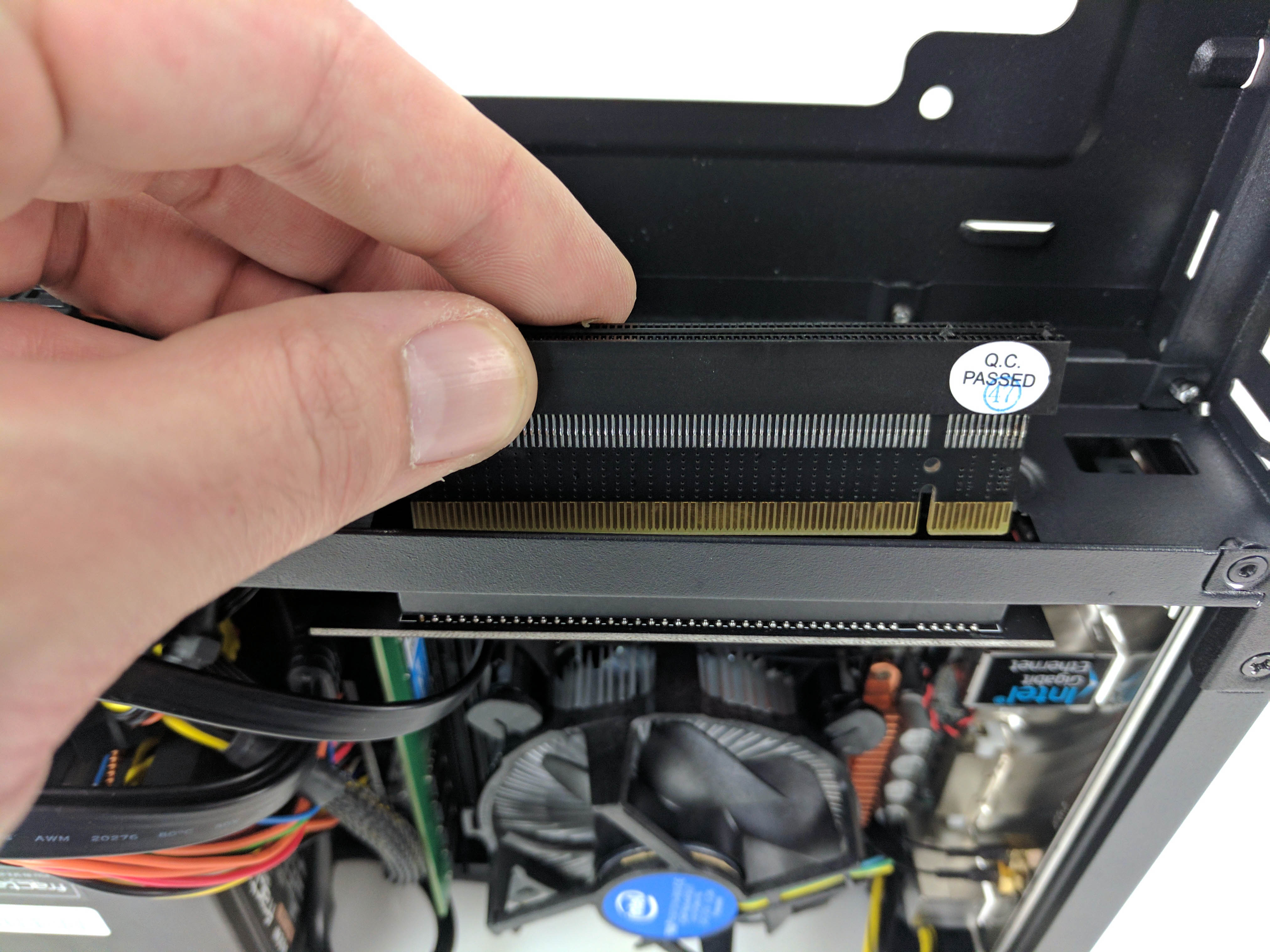
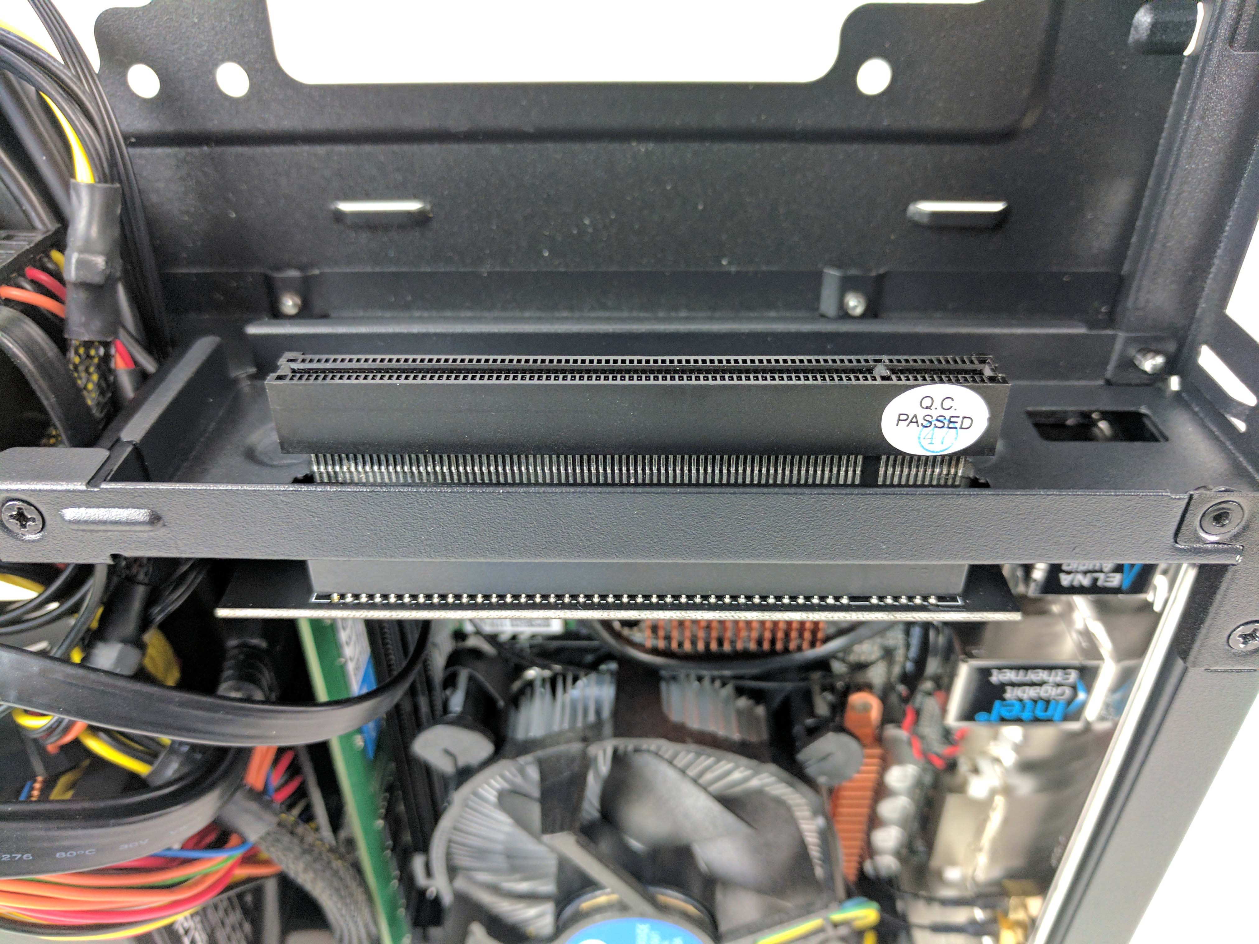
The center support beam that separates the GPU and CPU chambers of the chassis can be removed to install the PCIe riser card, which will accommodate our graphics card.
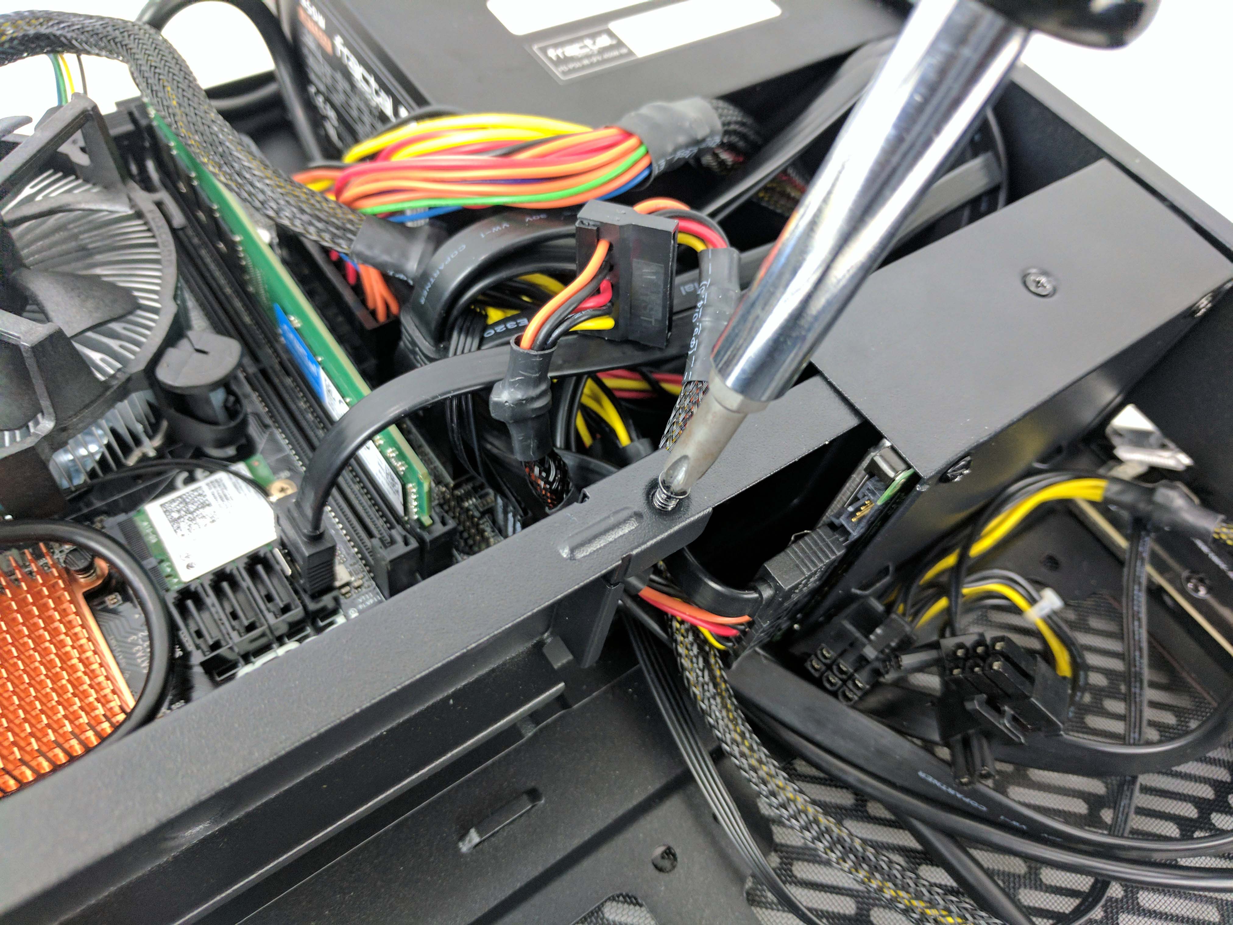
There are three screws that hold the beam in place and that are flush to the frame (see slides 1-3 in the album directly above), and one screw at the bottom of the case’s PCIe slots (slide 4).
Remove the screws and lift the GPU riser mounting bracket out of the case (slide 5 above).
Locate the two PCIe riser cards (see slide 7 above).
Attach the larger board to the removed chassis plate by lining up the three holes in the PCB and using the thinner threaded screws to secure it (see slides 9 and 10 for reference). The PCIe plug should be pointing down, and the angled PCIe slot lined should be lined up to the gap in the frame.
Reattach the frame to the chassis, connecting the PCIe plug to the motherboard’s slot (see slide 11 above).
Secure the cage to the case with the screws and connect the PCIe extension to the slot that feeds into the GPU chamber of the case (use slides 12-14 as a reference).
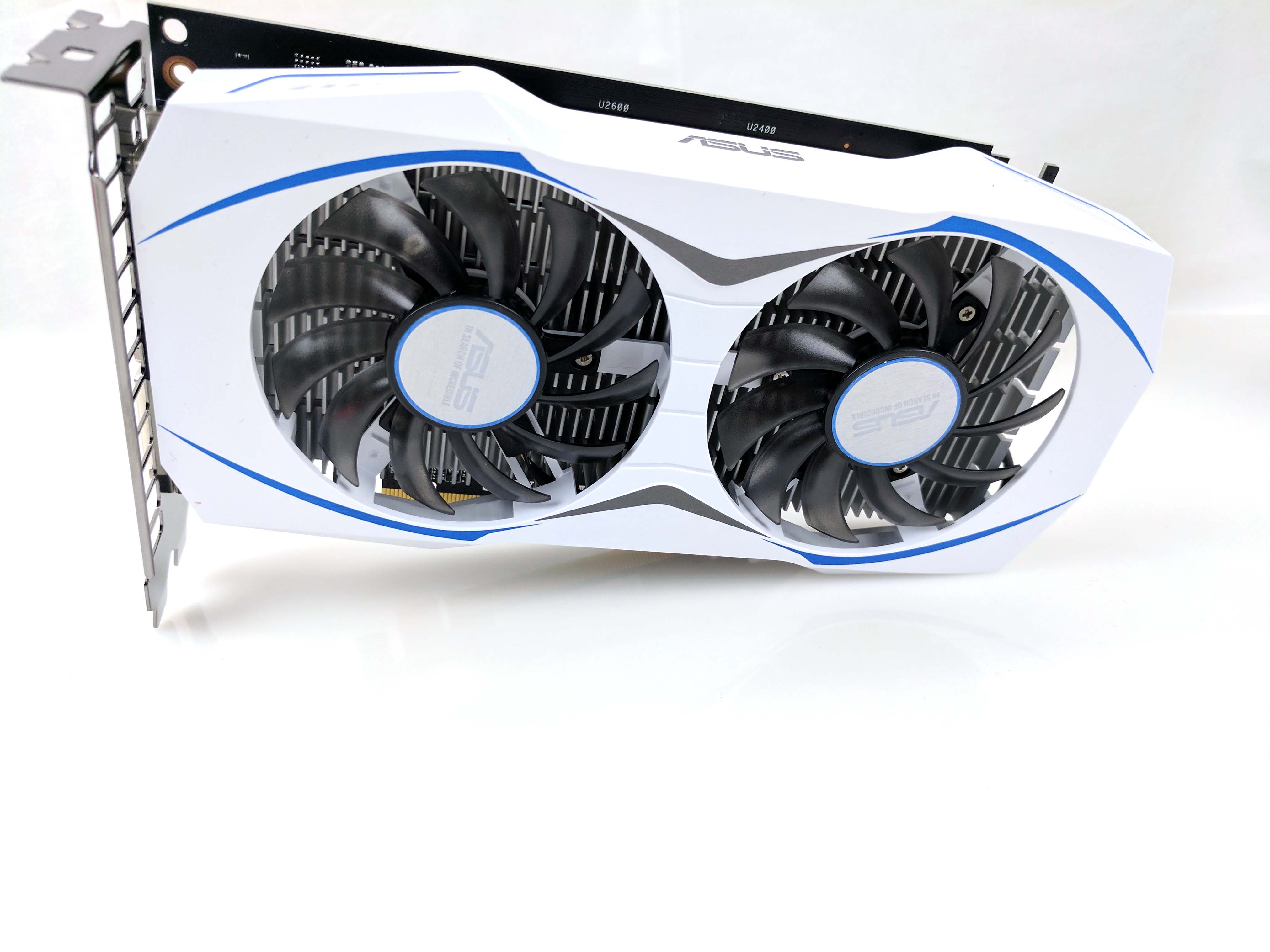
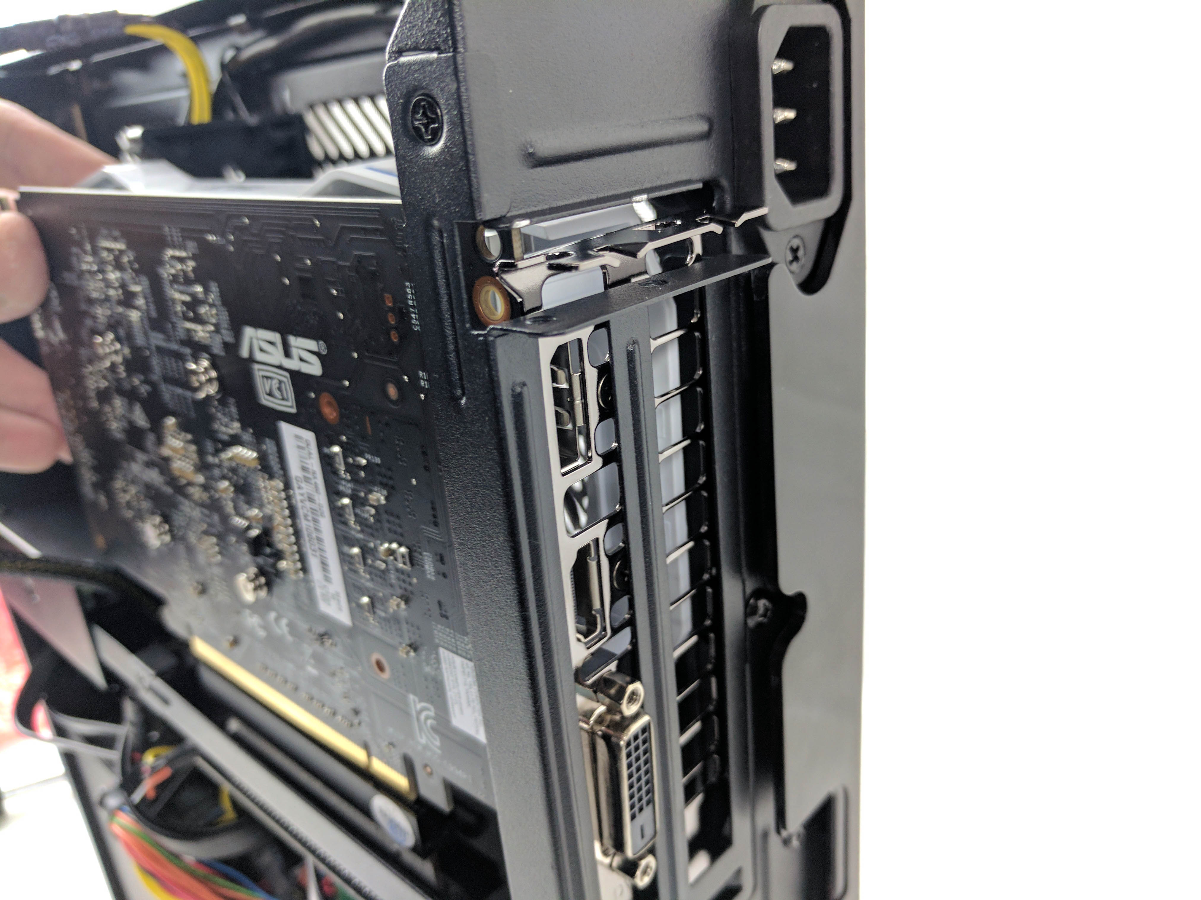
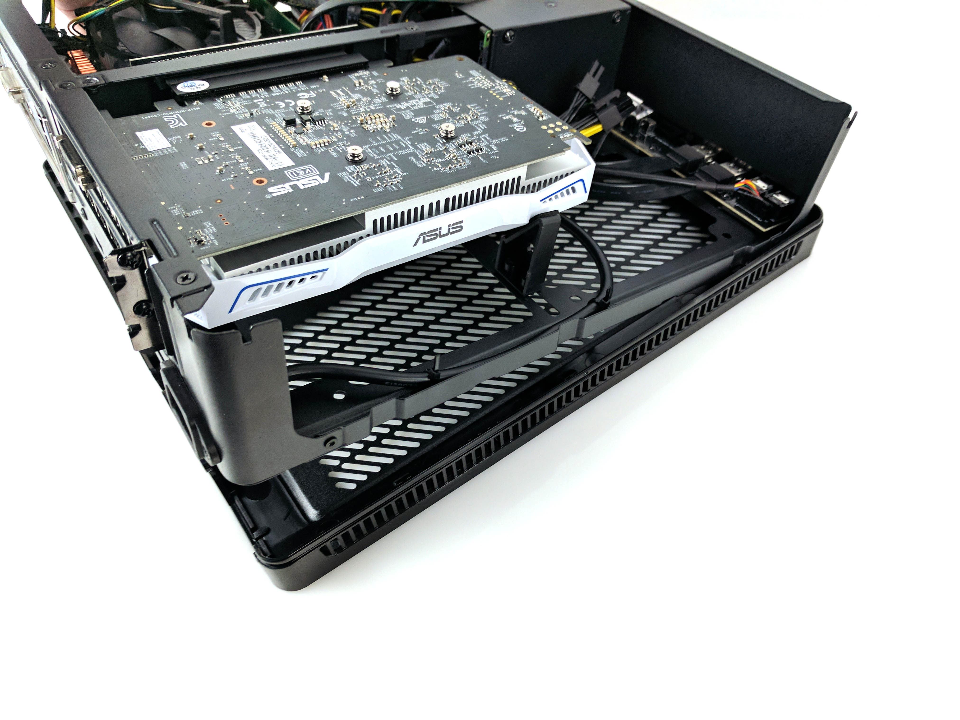
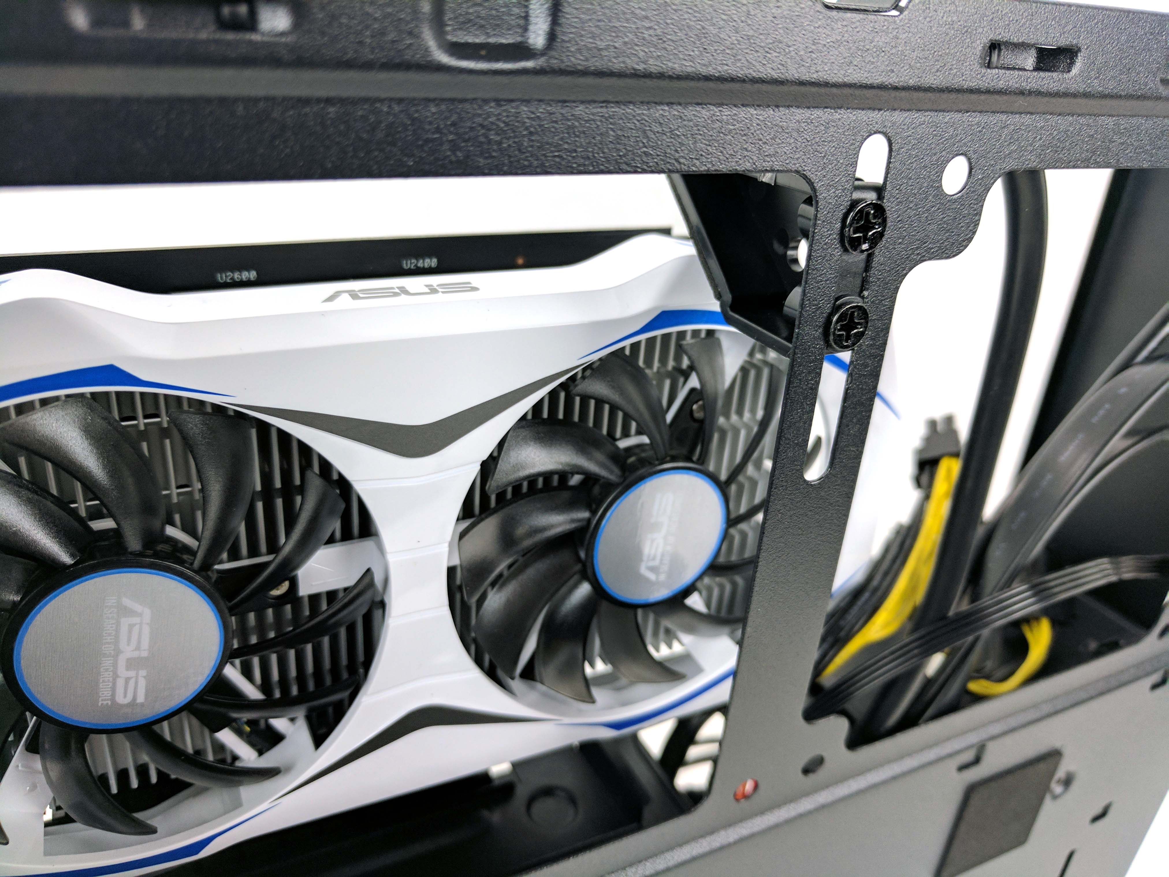
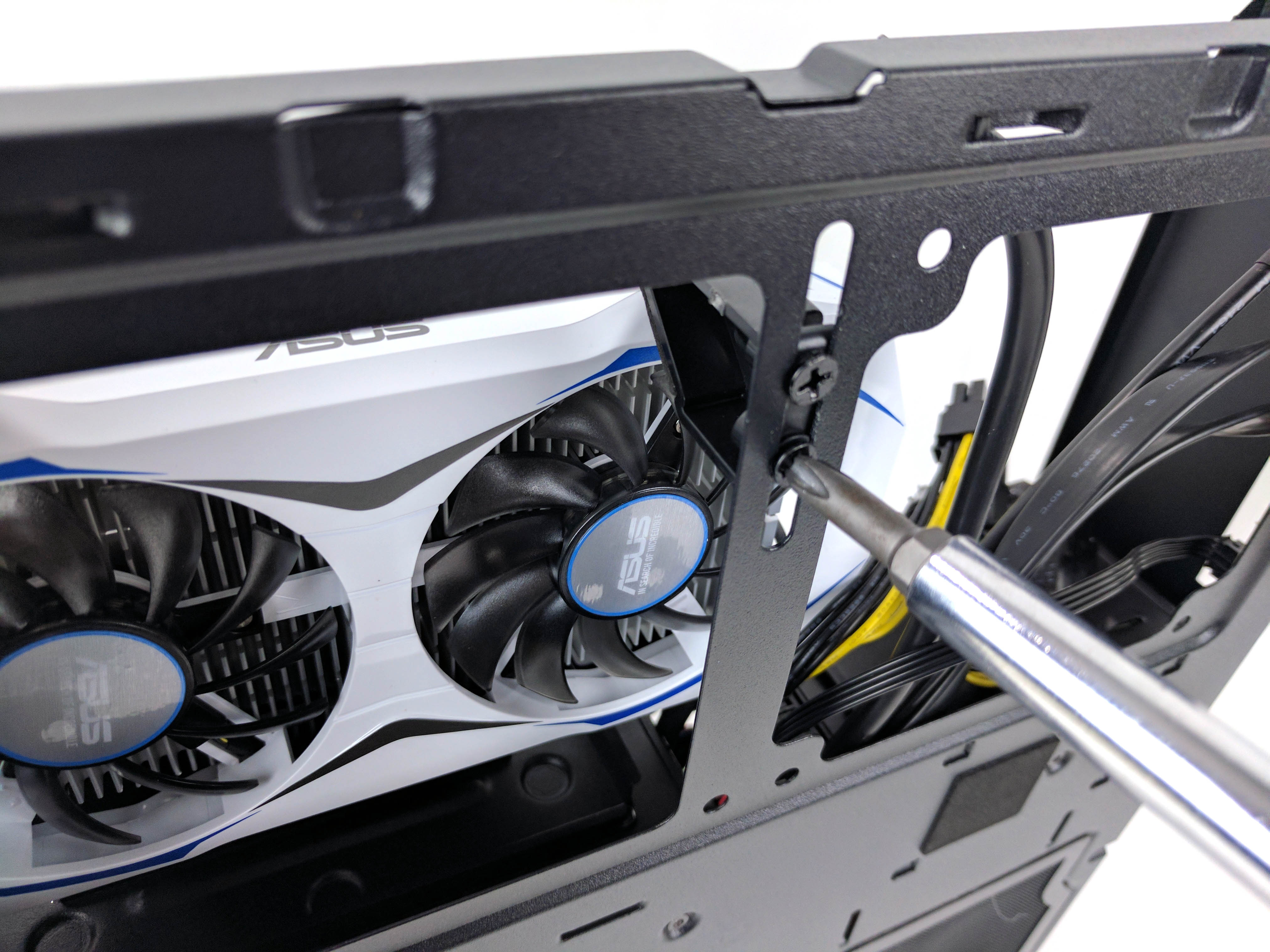
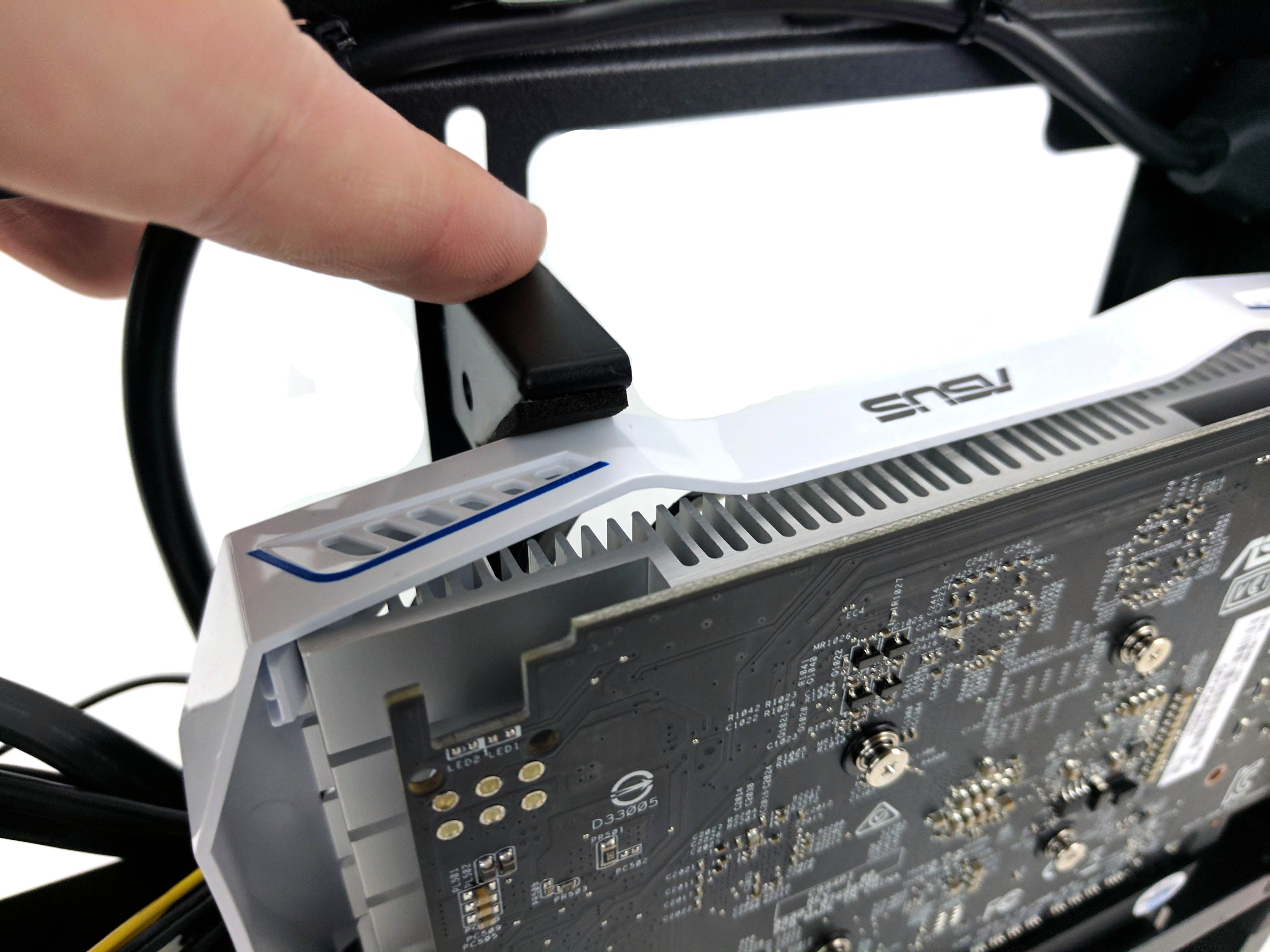
Finally, free the Asus Radeon RX 460 graphics card from its box.
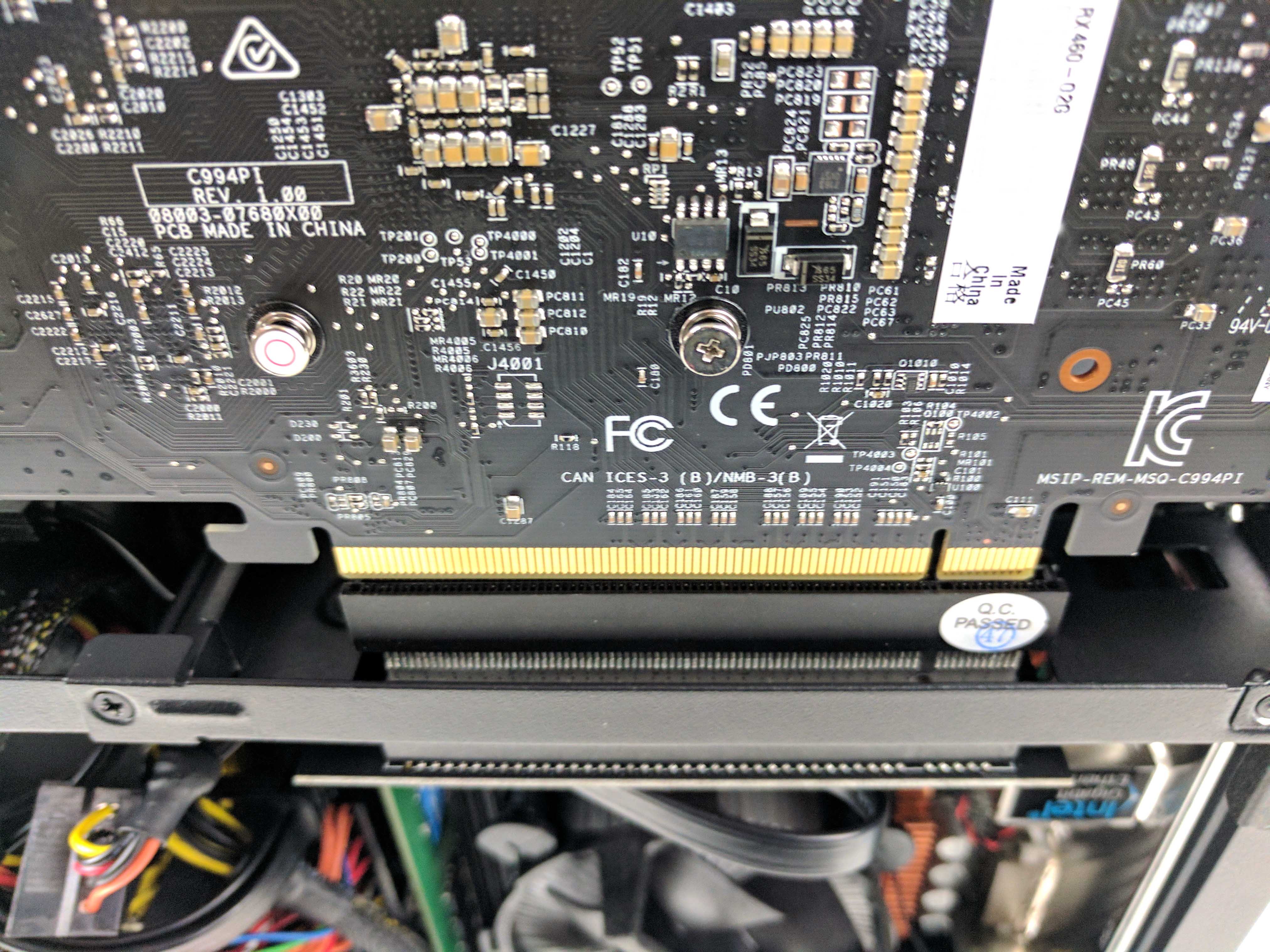
Carefully line up the GPU to the PCIe extension (attached to the riser, from the motherboard) and make sure the rear I/O panel tucks properly into the case so that when you push the card into the slot, the GPU bracket is flush to case’s the mounting bracket (see slides 2 and 3 directly above).
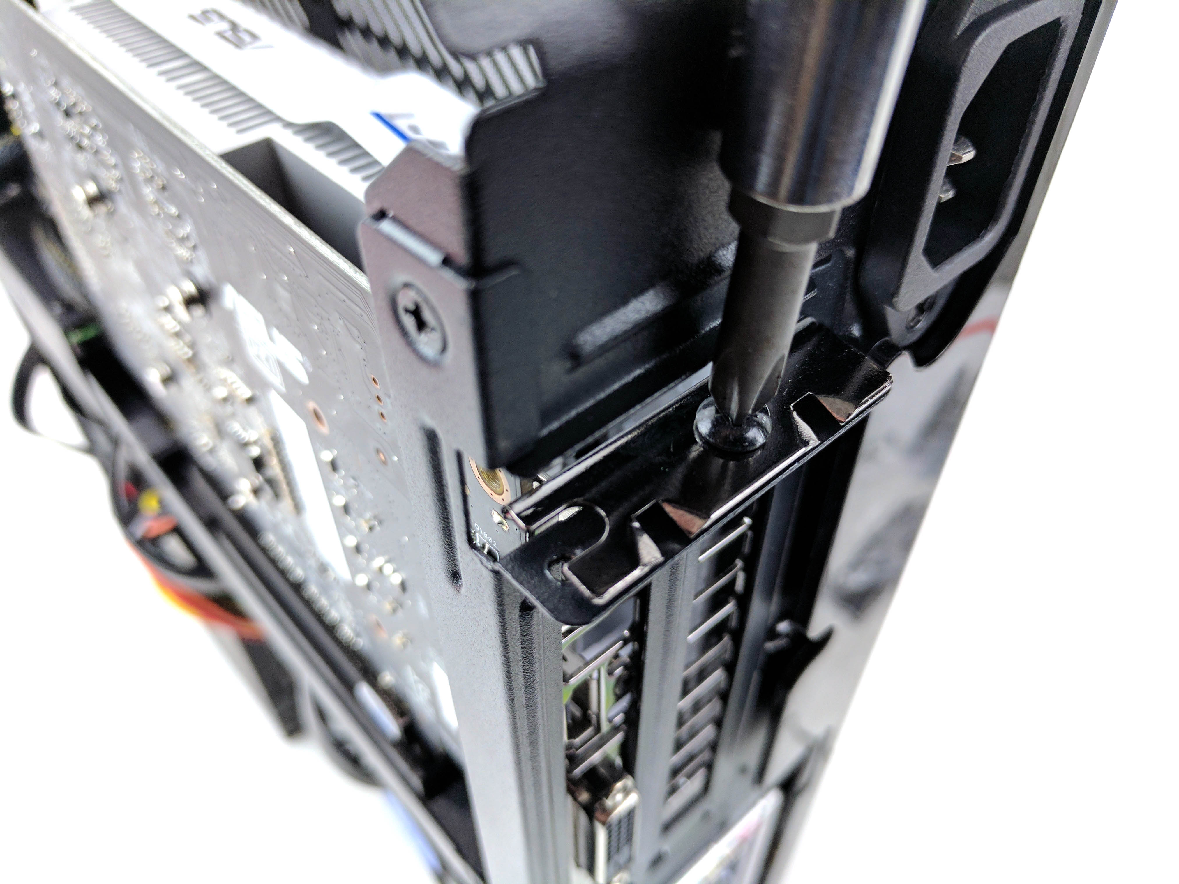
Secure the GPU to the case using two screws. If you haven’t already, remove the bottom case panel so that the frame is completely accessible (see slide 5 above).
On the backside (bottom) of the case, there is a sliding bracket that is used to stabilize the graphics card. Loosen the screws holding it in place, adjust the bracket so that it cradles the GPU snugly, and tighten the screws to secure it (see slides 6-8 above).
Finishing Touches
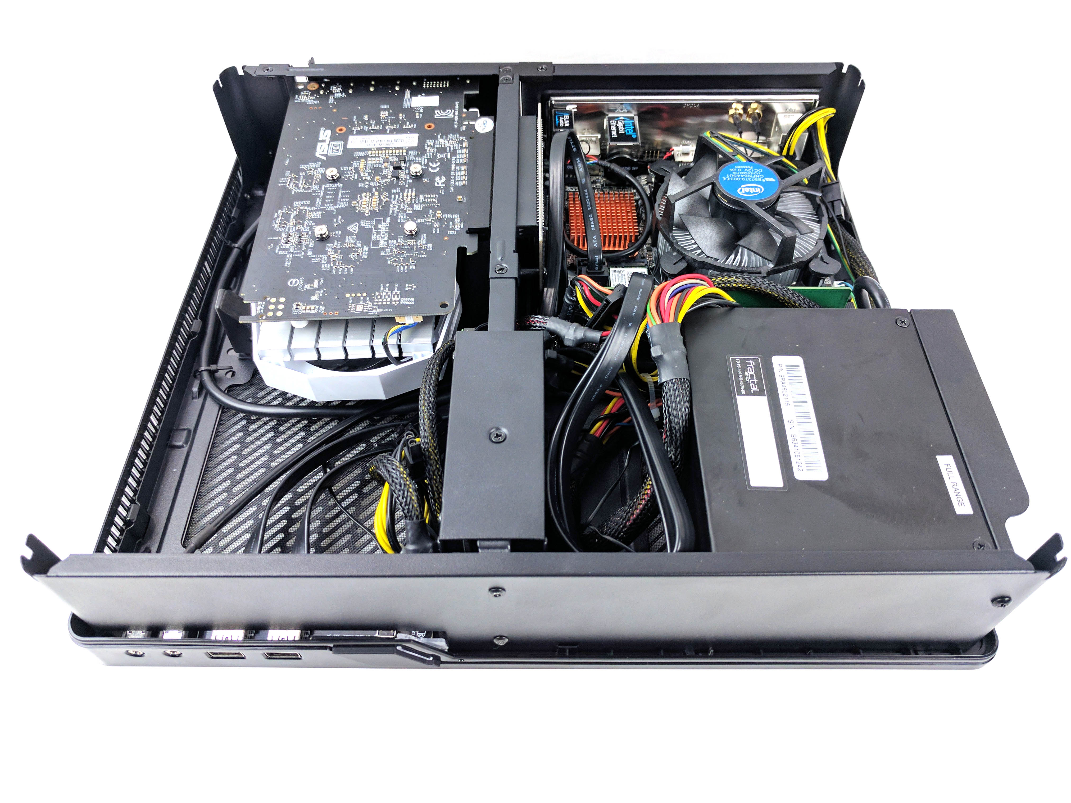
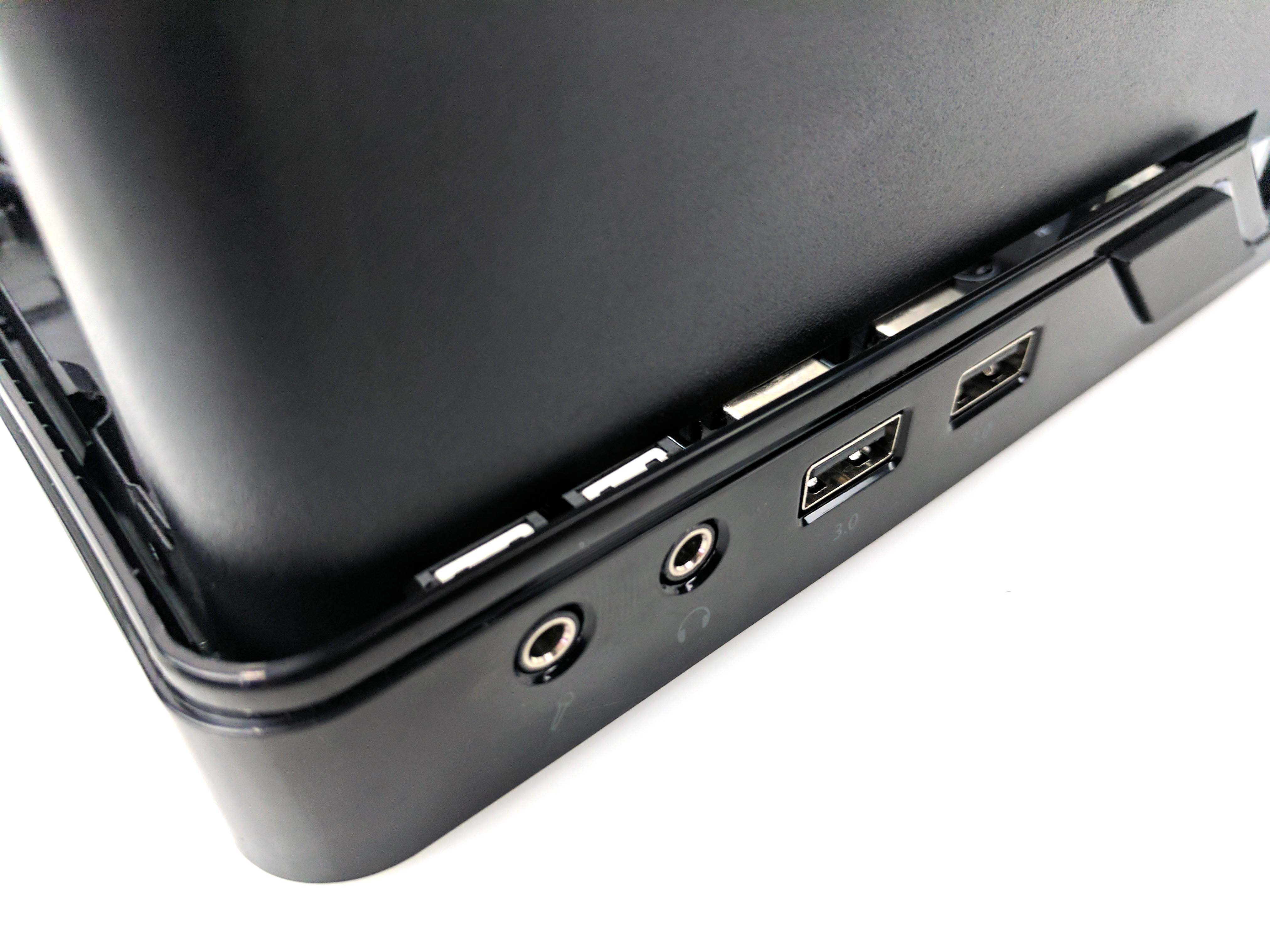
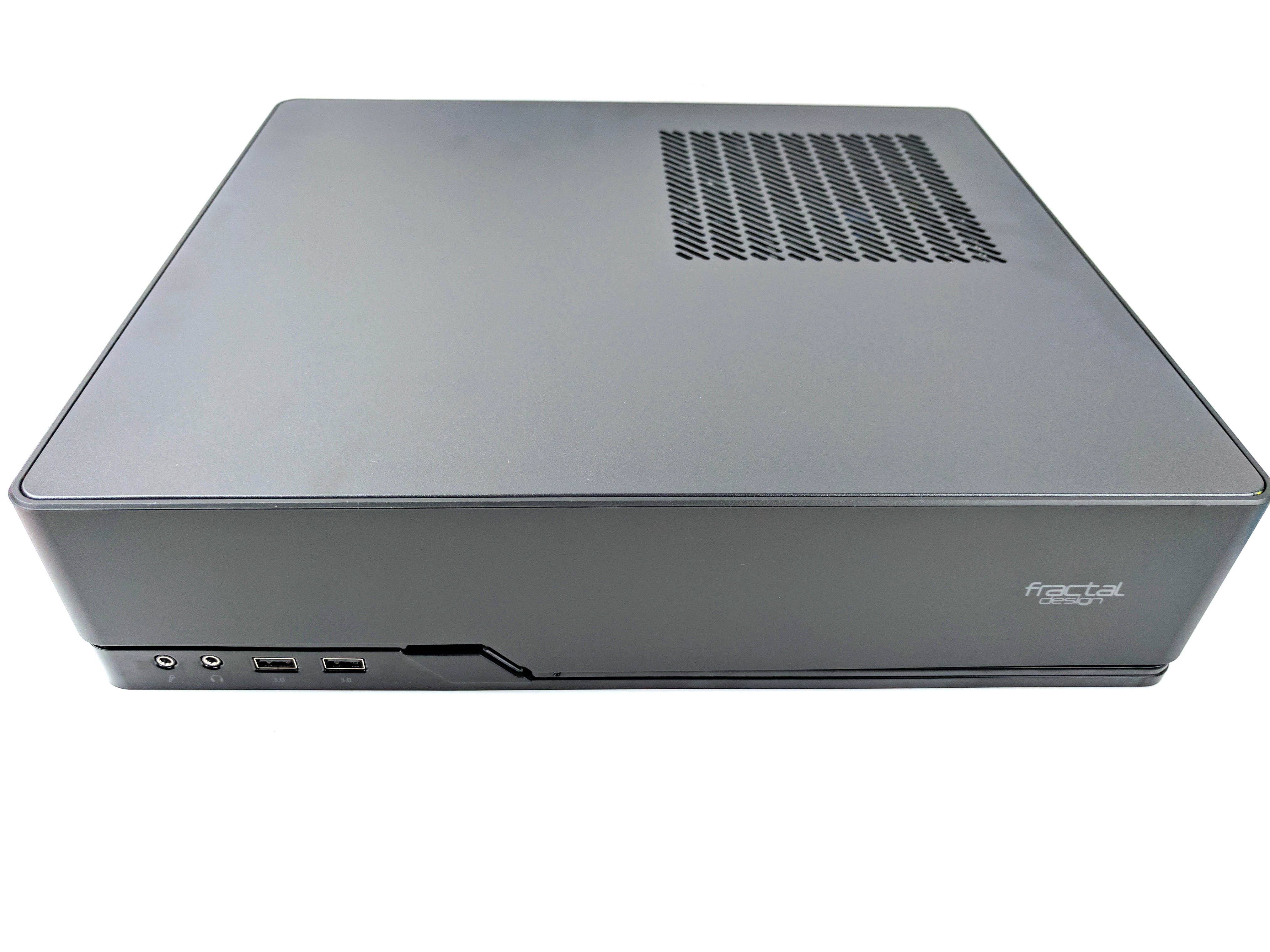
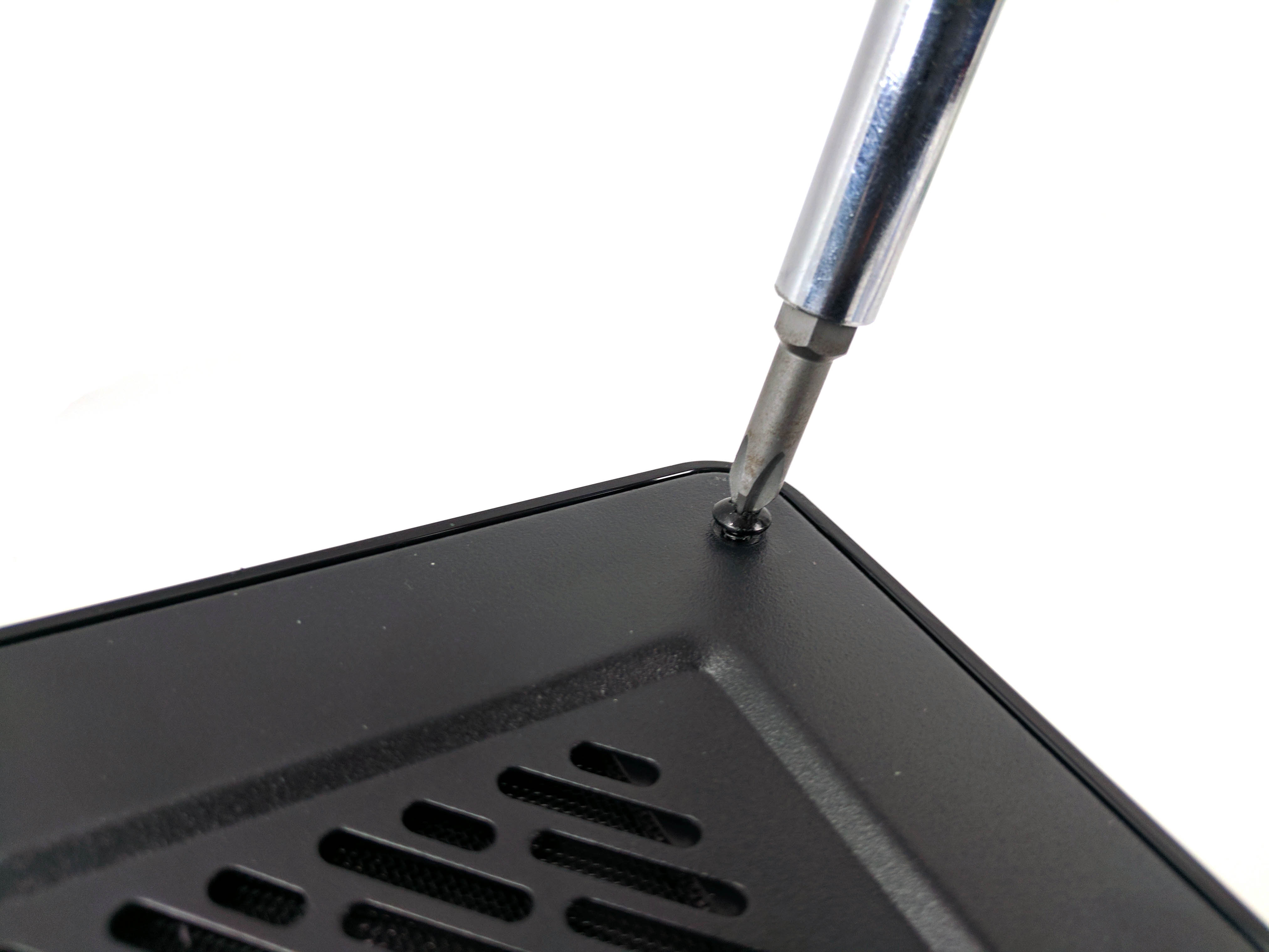
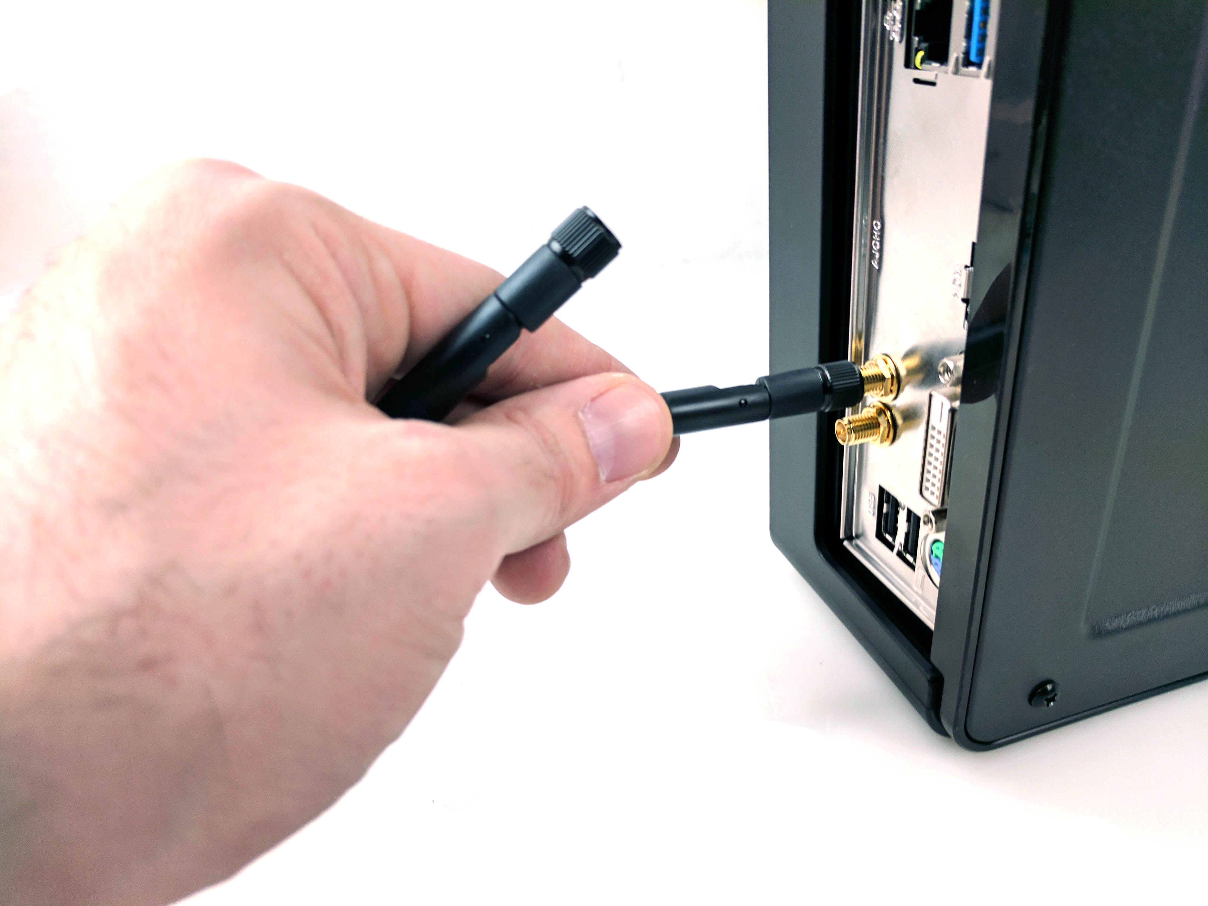
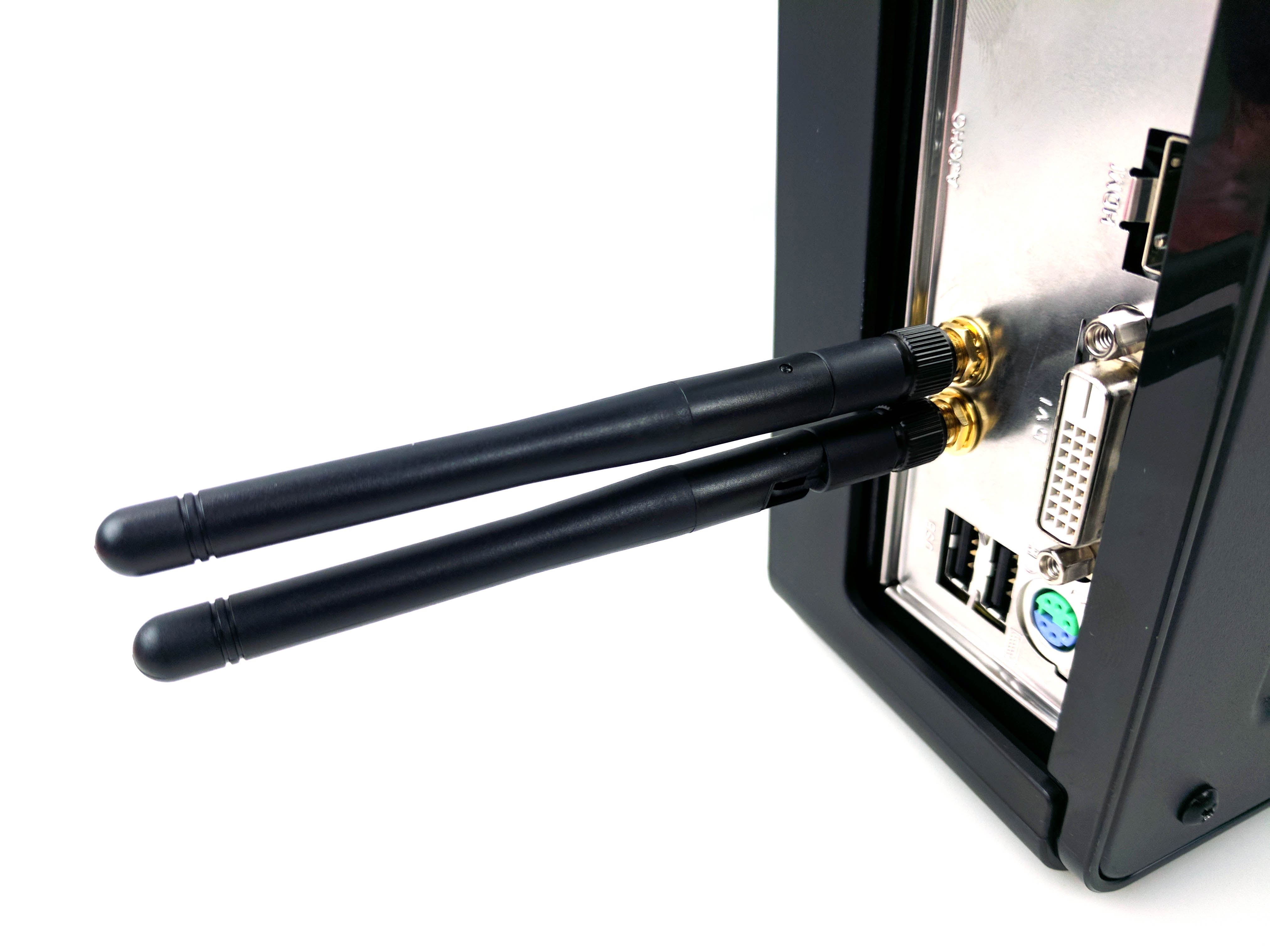
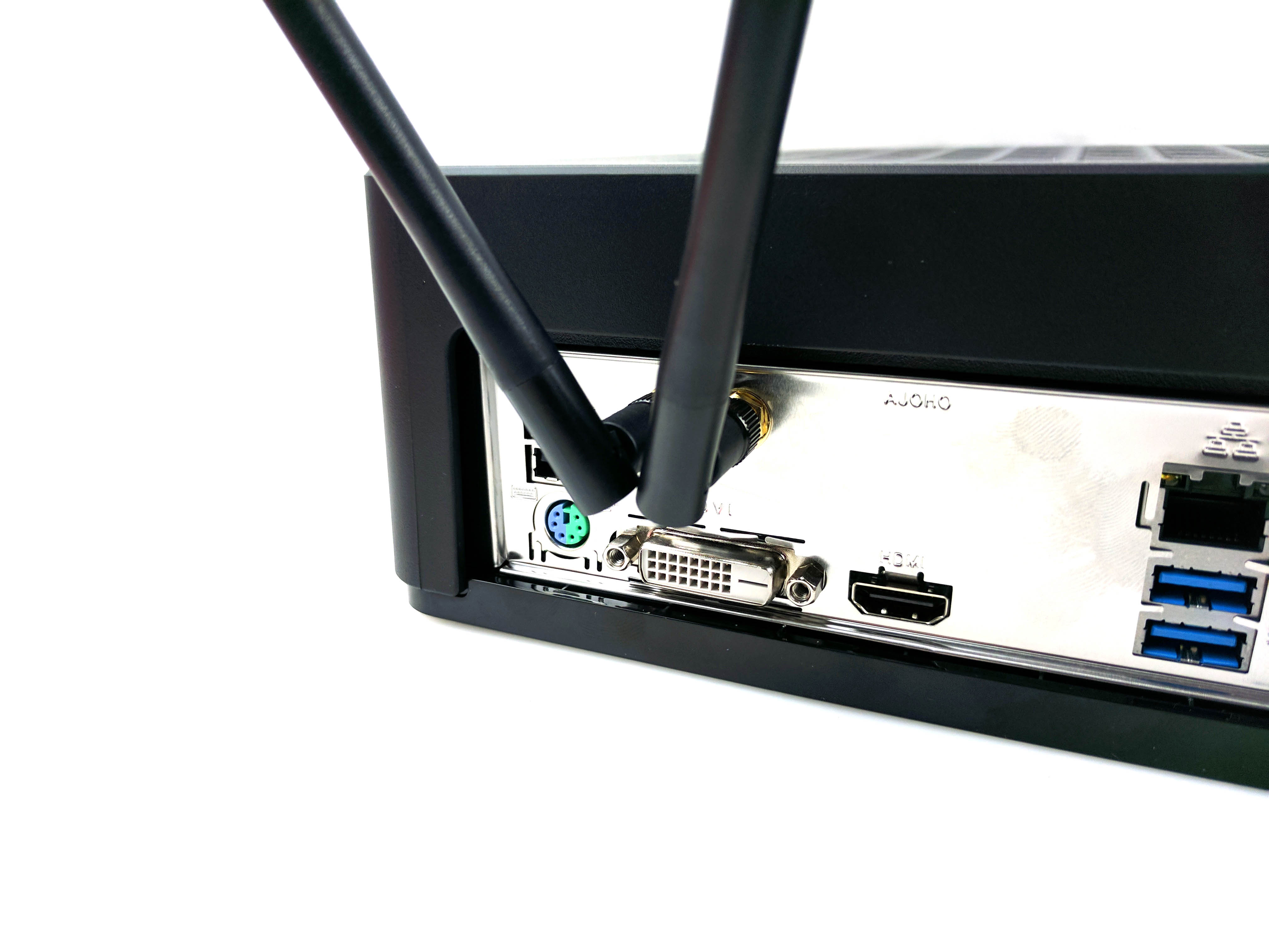
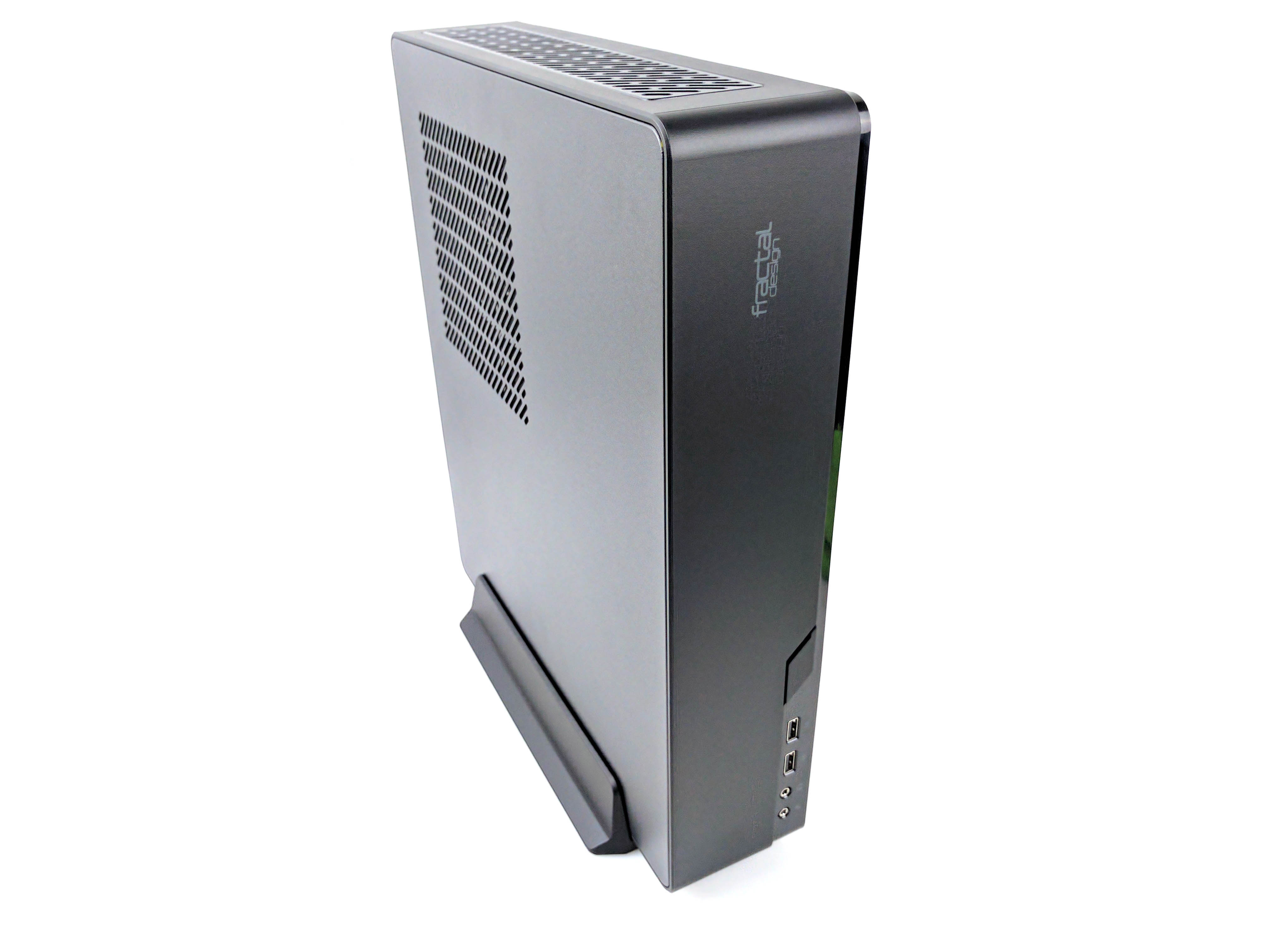
With all of the components installed, make sure that the cables are tucked away so that they are in the clear as you reattach the case panels.
First, set the chassis into the bottom case panel (front I/O panel first - see second picture in album above) and slide it into place until it clicks.
Then slide the top panel back into place. Carefully flip the entire chassis and use the four screws to secure the panels in place (fourth picture in the album above). As you are attaching the panels, make sure the magnetic fan filters are in their proper place (we had to remove the panels again because the GPU filter had shifted).
Attach the motherboard’s antennas to the threads in the rear I/O panel, plug in the power supply, peripherals, and display, and boot up your new $500 mini-ITX budget gaming PC.
Setup Tips
Before loading an operating system, be sure to update the BIOS and get all the latest drivers from ASRock’s website. This will ensure that you have the latest compatibility and performance updates, which is a must-have with this configuration (the older motherboard may not ship with a BIOS compatible with 7th generation Intel CPUs). To update the BIOS, use a different computer to download and unzip the Instant Flash version of the BIOS file and place it on the root directory of a thumb drive. Plug the thumb drive into the new build. Boot the machine and press the F6 key to access Q-Flash. ASRock’s BIOS update utility will automatically detect the thumb drive and the BIOS file, asking you to confirm the operation. Hit enter to execute.
The H110 chipset doesn’t offer overclocking, and there isn’t a need to set the XMP profile, so once the BIOS updates you can begin the process of loading an operating system.
Benchmark Results
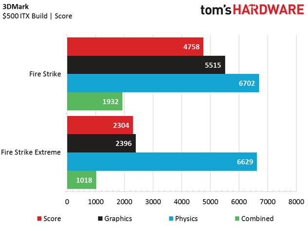
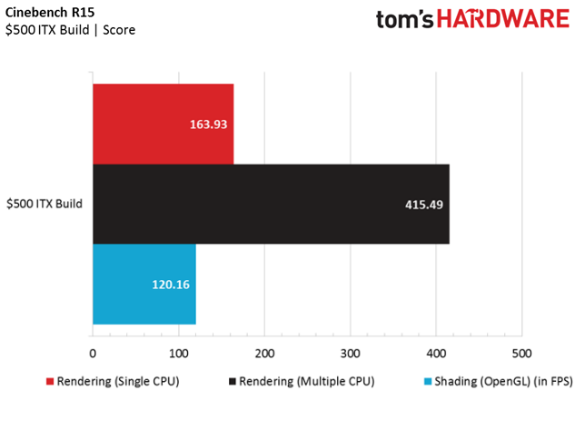
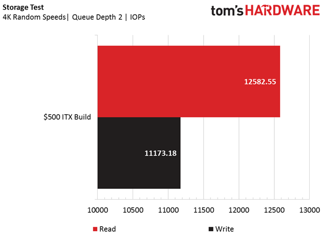
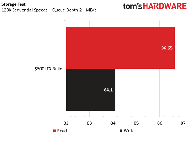
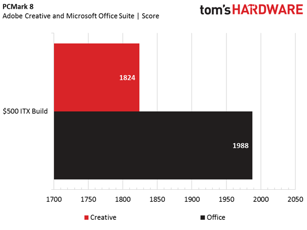
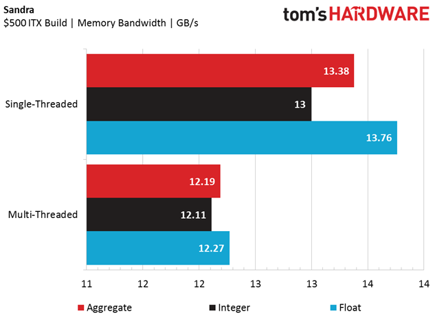
The Intel Core i3-7100 reaches a 3.9GHz all-core frequency (two cores, four threads), and the locked CPU is a fair match for the older H110 chipset. The 8GB of DDR4-2133 sports a CAS latency of 15-15-15-36, and the Asus Radeon RX 460 2GB graphics card reaches 1224 MHz in Gaming mode and 1244 MHz in OC mode.
The shortcomings of the $500 Best PC Build are apparent in the productivity and synthetic tests, with low scores in PCMark 8 (Word and Adobe Creative Suite), due largely in part to the slow storage and dismal total memory bandwidth (see: Sandra results), thanks to the single 8GB DIMM of DDR4-2133.
The 3DMark results also speak to the build's entry-level component set, with scores that barely qualify the system for 1080p at High to Ultra detail settings. Running Fire Strike Extreme was probably too ambitious in retrospect, but at least the system didn't crash. On a positive note, the Physics (CPU) scores in both tests ride just below those of a Core i5 CPU, which is a testament to the Core i3-7100's above-average clock rate (3.9GHz).
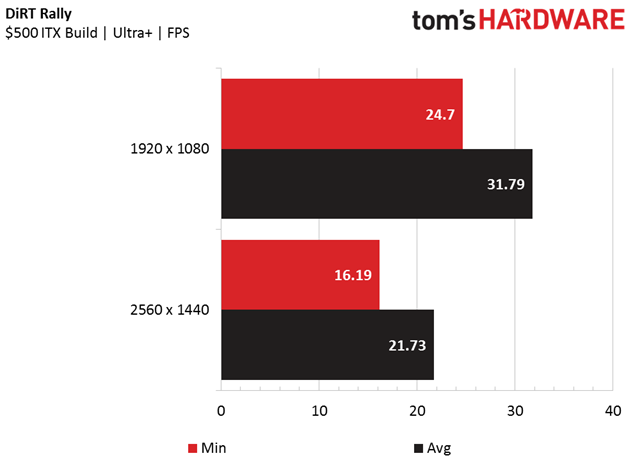
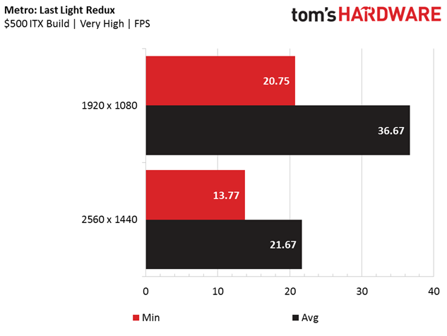
We were also a bit too ambitious with some of our gaming tests. We ran Metro: Last Light Redux and DiRT Rally at 1920 x 1080 and 2560 x 1440 at the highest detail settings (although we turned off SSAA and MSAA on Metro and DiRT, respectively). The $500 Best PC Build admirably achieved playable frames (30+ FPS) at only 1080p on these settings, and you'll make it to the 60 FPS sweet spot turning things down a few notches.
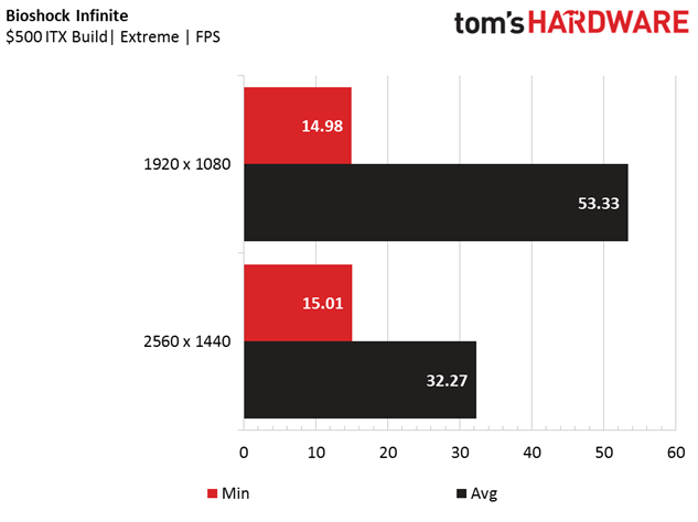
We also gave Bioshock Infinite our regular full-throttle test run (Ultra DDOF) at 1080p and 1440p, and we were surprised with impressively high average framerates at 1920 x 1080 (nearly 54 FPS). It was even playable (above 30FPS) at 2560 x 1440. The Core i3's speedy clock rate and hyper-threaded cores are to thank in this CPU-sensitive game test, but the minimum framerates indicate subpar frametime variances. Still, it's impressive to pull those numbers at those settings for this price.
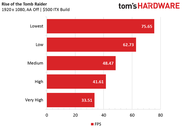
We turned off all anti-aliasing (AA) in Rise of the Tomb Raider and stuck to varying detail presets at 1920 x 1080. This is primarily because Tomb Raider is known to stress the platform (this rig barely meets the minimum requirements), and the RX 460 and Core i3 don't come near the game's recommended specs. Turning it down to the Low and Lowest presets is the only way to get the game to play comfortably above 60 FPS.
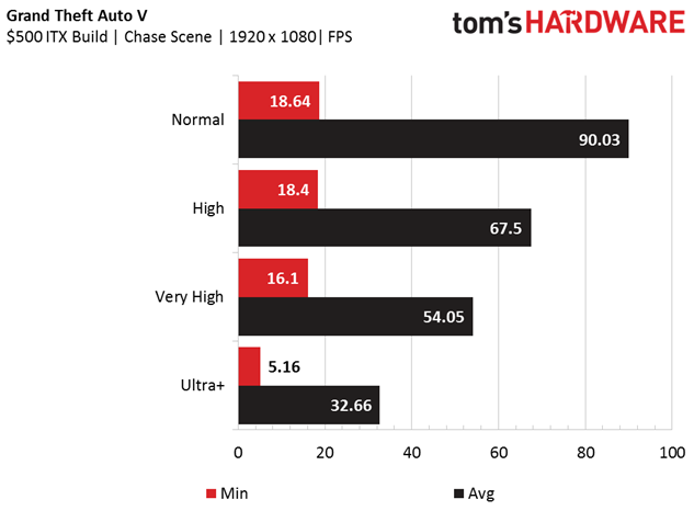
Similarly, we ran GTAV at multiple detail settings at 1080p, and it proves to be quite playable on even the $500 Best PC Build when you turn off MSAA (leave FXAA on) and turn down the detail dial. We didn't test at 1440p, but the range of detail settings at 1920 x 1080 show that you can get excellent framerates when you switch to a less power-hungry form of AA.
Final Analysis
Designing a $500 build is a tough task, and the star of this show is the Fractal Node 202 mini-ITX case, a smart choice for any mini-ITX build. Although there are other mini-ITX options out there, we’re thoroughly impressed with the Fractal Node 202.
The included 450W power supply can support moderately beefy configurations (up to a GTX 1060 GPU and Core i7 CPU), and it has plenty of juice for the current configuration (we didn't even use the PCIe power cable). However, if you have aspirations to upgrade, you can purchase the case sans PSU and invest in something with more juice for an even more powerful platform.
For the money, the Intel Core i3-7100 is a great entry-level gaming chip, but you could save a few dollars with an Intel Pentium G4620 - another popular pick from our community in this category. You could also save even more with an Intel Pentium G4560. Freeing up that cash will offer the opportunity for performance gains with other components, but balancing out your platform depends on what your ultimate goal for this machine is.
The ASRock H110M ITX/ac motherboard is an ideal starting point for any mini-ITX platform. This is especially so if you aren’t looking to branch into unlocked CPUs (which would also require a low-profile cooler purchase). Setting up the wireless internet antennas can be difficult (big hands, small leads), but you’ll be hard pressed to find another motherboard with an 802.11ac WiFi card for under $85.
Let's play a little arm-chair quarterback here, just so you know some of the other choices you can make to tweak this build.
We’re not put off by the pairing of a 7th-generation CPU to a 6th-generation motherboard, but you could likely shave a few dollars off by going with the Intel Core i3-6100 without a noticeable performance difference. Kaby Lake CPU features such as Intel Optane and higher memory bandwidth go to waste with this particular configuration, so switching to the 6th-generation counterpart doesn’t hurt the applicable feature set of this $500 build.
The platform could offer better performance with a dual-channel memory kit instead of a single module, and the Crucial CT2K4G4DFS8213 8GB (2 x4GB) DDR4-2133 kit only costs a few dollars more. Why_Wolf chose the single 8GB module as means to get to 16GB down the road, but we're not sure how we feel about a Core-i3 build with 16GB of RAM (a feels a bit like the carriage before the horse). If you're not looking down that particular upgrade path, you'd be better off with two 4GB modules.
The storage options at this price point are mostly the same, and the best you could hope for is a modestly priced 7,200RPM hard drive (because ew, 5,400RPM). However, if you have a flexible budget, an SSD would be one of the biggest improvements that you could make. We often found ourselves waiting for programs to load (especial Adobe products and games) for what seemed like forever (we’re spoiled), and an SSD would alleviate much of that grief.
MORE: Best SSDs
If you have a much larger budget, we’d also suggest bringing the platform up to VR-ready performance by replacing the Core i3 with a locked (non K-series) 6th or 7th generation Intel Core i5 processor, in addition to upgrading the GPU to at least a RX 480 or Nvidia GeForce GTX 1060. There are plenty of SFF graphics cards that would fit perfectly in this case, and a little more horsepower under the hood could turn this build into a wonderful VR gaming machine for the living room.
MORE: AMD Radeon RX 480 Roundup
MORE: Nvidia GeForce GTX 1060 Roundup
MORE: Best Deals
MORE: How To Build A PC
MORE: All PC Builds Content
Derek Forrest was a contributing freelance writer for Tom's Hardware. He covered hardware news and reviews, focusing on gaming desktops and laptops.
-
brenthainzer When I click on the link for the graphics card, it takes me to a page for a 4GB not a 2GB. Will this work?Reply