Going Out Without A Bang

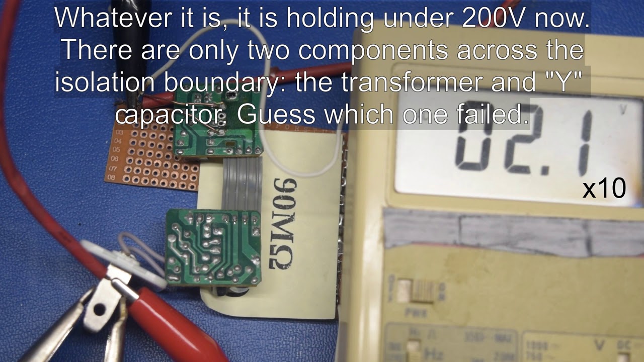
With the USB connector shield no longer providing a path between the optoisolator and output, the next thing to fail was the no-name 1kV capacitor at 1330VAC, which is 1875VPeak or almost twice its nominal rating and 3125V short of the proper Y2 capacitor that should have been there. After its failure, the capacitor’s leakage current increased in such a way that it clipped my 10mA transformer’s output to 180-200VAC somewhat like a MOV.
Could the capacitor fail as a low impedance and end up directly connecting mains to output? Certainly. That’s why safety standards require Y-class capacitors across isolation boundaries, making this as unlikely as practically possible.
MORE: 10 Inexpensive Automotive USB Adapters Tested
MORE: Best Deals
Undead Capacitor

Although this 1nF capacitor is no longer capable of withstanding more than 250V or so of its 1kV nominal rating, it still reads 1.17nF on the capacitance range and overload (>100MΩ) on the resistance range. You wouldn’t know it failed without doing an actual voltage withstand test on it. When I re-did the voltage test on the capacitor after removing it from the adapter, its reading increased to 300VAC.
MORE: 10 Inexpensive Automotive USB Adapters Tested
MORE: Best Deals
What Does It Take To Kill This Thing?

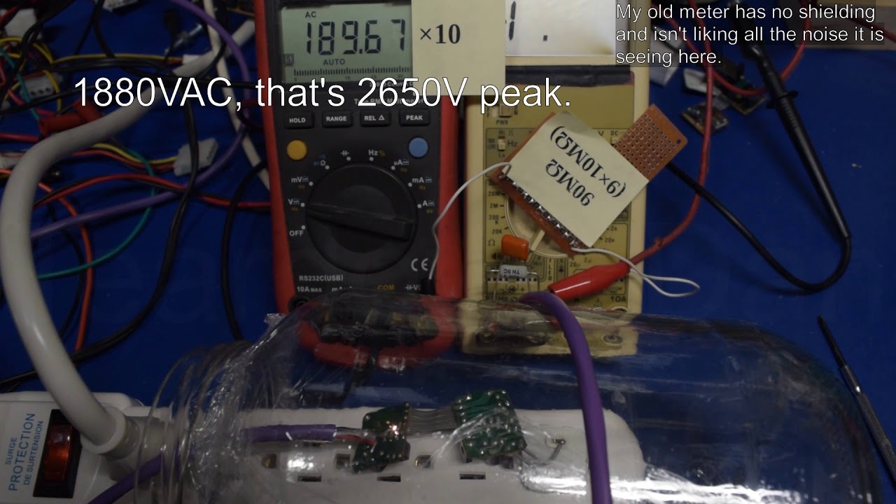
Does this adapter still work after the abuse so far? Surprisingly enough, the answer is yes. I decided to do this last round of isolation breakdown testing with the adapter live and being fed a 10Ω load. If arcs between the primary and output sides couldn’t kill the adapter outright, perhaps arc current through the live control circuit will cause a catastrophic failure.
My old meter freaks out from all the EMI it receives when the adapter begins to arc over at 1880VAC, while the adapter chugs along as if nothing happened between arcs.
MORE: 10 Inexpensive Automotive USB Adapters Tested
MORE: Best Deals
Close-Up

What does all of this arcing do to the circuit board? The hot plasma progressively eats away at the substrate material between solder joints, and in an open-air setup, that vaporized material wafts away, immediately filling the room with a pungent burning electronics smell.
MORE: 10 Inexpensive Automotive USB Adapters Tested
MORE: Best Deals
Digging A Hole

As you saw in the video, the first breakdown event occurred at 1880VAC but the residues left behind by the arcs allowed other arcs to occur at 1100-1300VAC across the same pads. Although the board looks spotless apart from a small crater the arc left behind, in an enclosed space without the benefit of airflow (within the adapter’s housing, for instance), the same material would sputter about the area and eventually yield a permanent resistive connection between traces or heavily contaminated areas with much lower breakdown voltage.
MORE: 10 Inexpensive Automotive USB Adapters Tested
MORE: Best Deals
Transformer Test

Now that the circuit board has been abused as much as possible, and is the limiting factor to finding out how good the transformer’s insulation really is, we'll pull off the transformer and rig it for standalone testing. All of the primary-side windings are shorted together and connected to one terminal from my HV transformer. The same goes for the secondary side and other HV terminal.
The passing mark? 3500VAC (5kV peak) to match a proper Y2 capacitor’s 5kV pulse withstand rating.
MORE: 10 Inexpensive Automotive USB Adapters Tested
MORE: Best Deals
There Goes The Transformer

How much voltage does it take to fry the transformer’s insulation or get a failure of some sort? A small flash near the secondary side’s terminals answers that question at 2770VAC, 730VAC shy of a pass. Time to do an autopsy and find out how it failed.
MORE: 10 Inexpensive Automotive USB Adapters Tested
MORE: Best Deals
First Layer

I was hoping to at least salvage the transformer core and coil form from these adapters, but the cores are glued together inside the form, so I had to shatter the ferrite to gain access to the windings. Under two layers of thin black tape, we find the feedback winding sitting in the middle of the yellow tape with none of it anywhere near the spark area in the video. The spark source we’re looking for isn’t on this layer.
MORE: 10 Inexpensive Automotive USB Adapters Tested
MORE: Best Deals
Peeling Off

Insulating tape between the feedback winding and secondary got pulled taut around the secondary, and the feedback winding was wound so tight on top of it that the tape turned transparent in places from getting thinned out. While it didn’t fail, it may have been only a matter of time before pressure and heat caused the tape to flow out of the gap between windings and grow holes. Thicker tape or a third layer may be necessary here.
MORE: 10 Inexpensive Automotive USB Adapters Tested
MORE: Best Deals
Failure Area

Upon removing the feedback winding and underlying yellow tape, we find the secondary-side winding. Near the secondary-side terminal leg (where the spark appeared), we also see three exposed turns from the primary winding underneath. The purple tape creased between the secondary’s top two turns, possibly from snagging on the coil form’s edge while wrapping, leaving the top few primary turns exposed and the last secondary turn wound on top of them.
There's no other way to put it: this is a literally fatal manufacturing flaw.
MORE: 10 Inexpensive Automotive USB Adapters Tested
MORE: Best Deals