Aukey PA-U32 USB Power Adapter Tear-Down
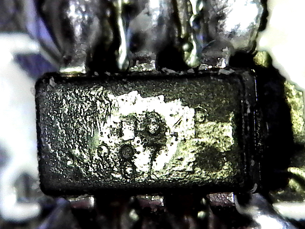
Switching IC
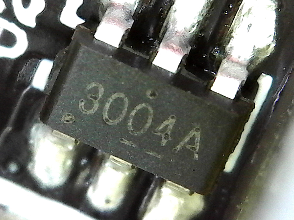
Two things tend to happen with tiny surface-mount packages: either the shortened device codes are undecipherable (unless you happen to be familiar with the specific manufacturer’s codes) or most of the chip code is eaten away by the wave soldering process, as in this case.
MORE: AmazonBasics ABHT1208TC Tear-Down
MORE: CyberPower EC350G Tear-Down
MORE: How (And Why) We Test USB Power Adapters
Slightly Splattery
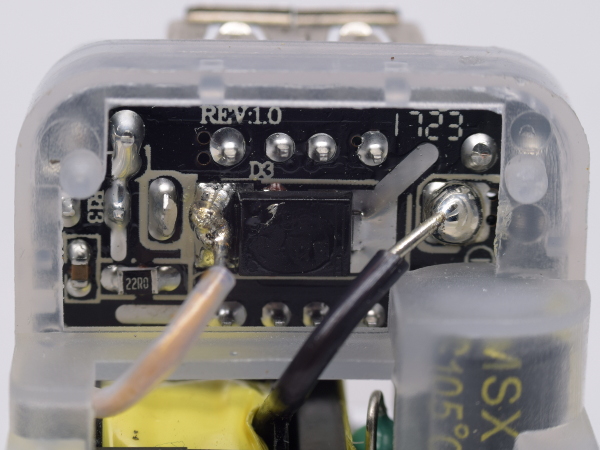
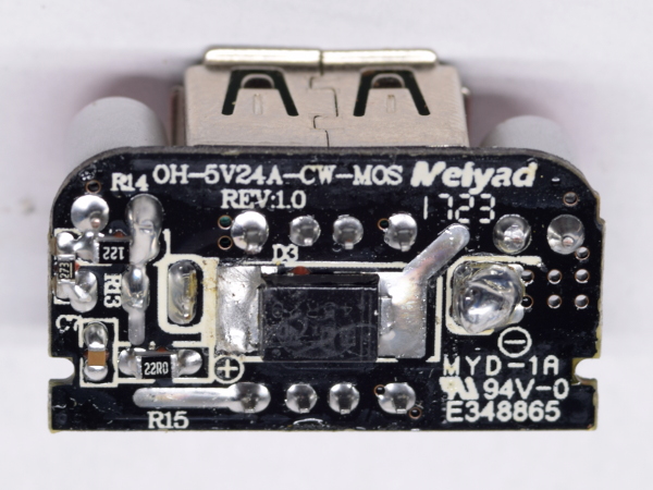
Since the transformer was connected to the board after being seated within the plastic frame, and from the other side, wire soldering had to be done in-place.
Soldering in awkward positions leads to oddly-shaped joints like the one on the diode, splatter, such as the flake you can see on the diode's body, and large blobs like the one to the right. To be fair, though, the negative terminal’s blob happens to be on top of the USB connector’s shield tabs.
MORE: AmazonBasics ABHT1208TC Tear-Down
Get Tom's Hardware's best news and in-depth reviews, straight to your inbox.
MORE: CyberPower EC350G Tear-Down
MORE: How (And Why) We Test USB Power Adapters
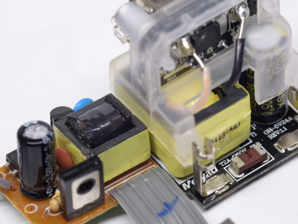
Separating Sections
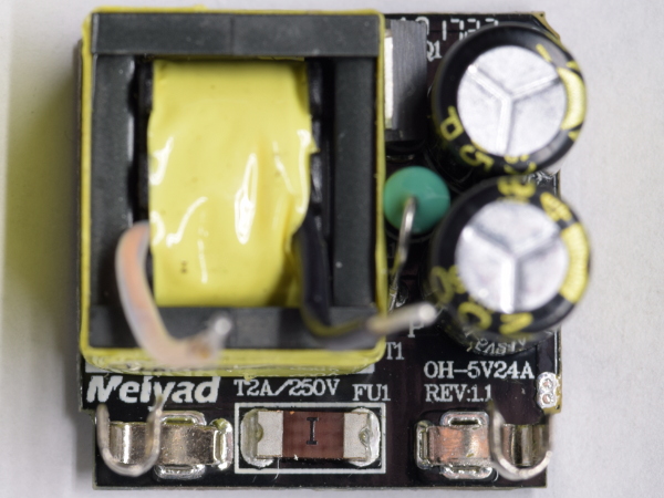
Are there any major top-side components hidden by the plastic frame? The only one we spot is a 470Ω resistor nestled between the transformer and two input capacitors. There's no Y-class capacitor or common-mode choke. And we can't find a hidden third or fourth wire going to the output board. It's really only connected through those two wires.
Since there is nothing else across the input and output boundary, I will be doing my isolation breakdown test directly between the AC input and the transformer’s output wires.
MORE: AmazonBasics ABHT1208TC Tear-Down
MORE: CyberPower EC350G Tear-Down
MORE: How (And Why) We Test USB Power Adapters
Output Board – Top
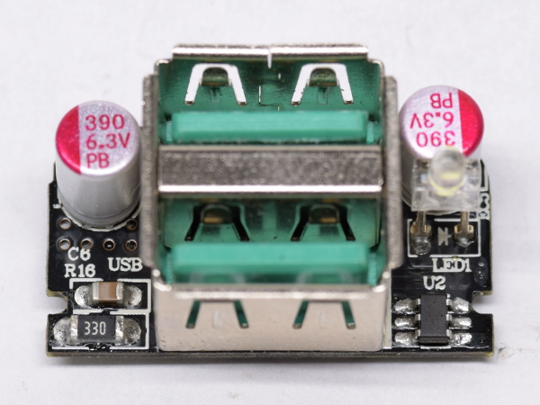
USB ports dominate the board’s footprint, which is only made slightly wider to flank them with a pair of 390µF filter capacitors and a few support components that won’t fit on the back, including a lone charger identification chip.
MORE: AmazonBasics ABHT1208TC Tear-Down
MORE: CyberPower EC350G Tear-Down
MORE: How (And Why) We Test USB Power Adapters
Output Board – Bottom
With most of the back’s edge making contact with the plastic frame, very little space is available for extra circuitry. We end up with a current-limiting resistor for the LED and support components for the tiny chip on the other side.
The surface-mount diode between the two USB connectors’ pins is labeled 45R20. I couldn’t identify its brand, and mostly came up with search results for radial tires, so I’ll hazard a guess that it stands for 4.5A/20V.
MORE: AmazonBasics ABHT1208TC Tear-Down
MORE: CyberPower EC350G Tear-Down
MORE: How (And Why) We Test USB Power Adapters
ID-ing The ID Chip
When I flipped the output board and didn’t see another SOT-363 package, I wondered where the second port was getting its ID from. After a few seconds of contemplation, I figured that a six-pin chip with power and ground pins had enough leftovers to afford two pairs of D+/D- pins by omitting the CW3002’s configuration pin. One quick microscope check later, my suspicion was confirmed by finding a CW3004A, a dual-port version of the CW3002.
MORE: AmazonBasics ABHT1208TC Tear-Down
MORE: CyberPower EC350G Tear-Down
MORE: How (And Why) We Test USB Power Adapters
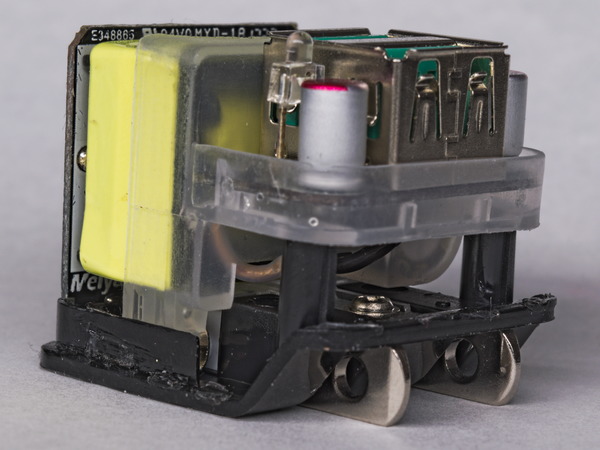
Empty Frame
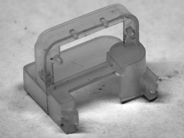
Photographing a translucent white subject while preserving its details is quite challenging. Thankfully, heavy contrast and edge enhancement help bring those back from oblivion, along with blemishes on my white sheet background.
The mold used to form this piece must have at least three parts: one for the bottom to form the output board's shelf, a front mold to form the recessed area above the transformer, and a back mold to form the transformer cut-out.
This may be one of the most expensive parts in there after the transformer due to its limited reusability.
MORE: AmazonBasics ABHT1208TC Tear-Down
MORE: CyberPower EC350G Tear-Down
MORE: How (And Why) We Test USB Power Adapters
Bare Frame On Base
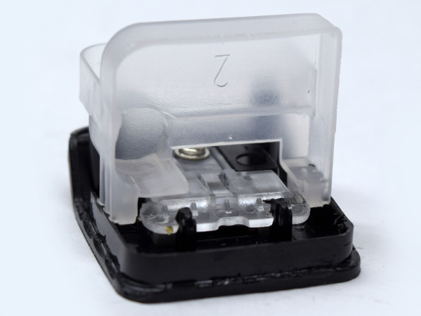
How does this all fit together? The frame, with its two locator pins and contact arms, simply plugs into the base once all of its components are mounted onto it. Then, the whole block gets slipped inside the front housing. Since the prongs are outside the enclosure and their internal contacts are all the way out along the housing edges on the input side, no exposed prong metal comes anywhere near the transformer's low-voltage wires.
MORE: AmazonBasics ABHT1208TC Tear-Down
MORE: CyberPower EC350G Tear-Down
MORE: How (And Why) We Test USB Power Adapters
Some Pre-Assembly Required
This is likely what the adapter looks like before it's inserted and sealed into the housing. The printed board extends a few millimeters into the plug base for its contact arms to reach the prong’s contacts. Above and closer to the middle, you can see the low-voltage wires going to the low-voltage board with at least five millimeters of clearance from anything mains-related, including a two-millimeter air gap.
Short of the adapter catching on fire, the transformer is the only thing that could realistically fail and let high voltage out through the low-voltage side. Considering the amount of design effort that went into it, though, I'd be seriously disappointed if the transformer failed my withstand test.
MORE: AmazonBasics ABHT1208TC Tear-Down
MORE: CyberPower EC350G Tear-Down
MORE: How (And Why) We Test USB Power Adapters
Side By Side
Bringing one of my A1265 wannabees in for reference, the PA-U32’s transformer is roughly 50% larger in all three dimensions, making it about three times as large by volume. That's in the same ballpark as the look-alike’s whole input board. Now you know where most of the 17g difference comes from. The extra 15µF input capacitor, internal frame, and foldable mechanism must account for the rest.
By now, it should be abundantly clear that a good chunk of those extra ~$8 went into better and safer design.
MORE: AmazonBasics ABHT1208TC Tear-Down
MORE: CyberPower EC350G Tear-Down
MORE: How (And Why) We Test USB Power Adapters
-
d.schrei3er About the "cracks" around the LED hole: three flowsthey are "knit lines" caused by the flow of plastic into the mold. Its pretty obvious that the plastic converged at the LED hole from 3 fronts: over, under, and in between the two USB holes. By the time the plastic reaches that location it has cooled enough (at least at the surface) that the 3 flows are not hot enough to fully weld. You comment that it seems solid, which it most likely is, and the obvious knit lines may merely be a cosmetic surface defect caused by minimising mold temperature, pressure, and cycle time past the bare minimum. I.e.: there's a reason this device only costs $9.99.Reply -
mikewinddale Thanks for doing these teardowns. I own two Aukey products: a 20,000 mAh battery pack and a Quickcharge charger. This teardown gives me some extra piece of mind.Reply -
Farrwalker This type of article is interesting to me. So may USB chargers out there and so little objective information.Reply
I recently bought three of Quick Charge 3.0,Onlier 30W Qualcomm USB Wall Charger 3-Port USB Fast Travel Adapter.
It is supposed to have the following features:
Quick Charge 3.0
4x faster than conventional charging. Charge a compatible mobile phone up to 80% in 35 minutes.
Charging Quicker, Using Safer
Protect your devices against excessive current, overheating, and overcharging; avoid any security issues happening.
Qualcomm Quick Charger 3.0 Specification
Input:100v-240VAC 50/60HZ.
Output :
1:DC3.6v-6.5v/3A Dc6.5v-9v/2A Dc9v-12v/1.5A
2:DC5V2.4A max
3:DC5v 2.4A max -
Xajel I have a very good experience with AUKey in their cables, I use Type-C ( with QC 3.0 phone and charger ) and Lightening and both are awesome.. I had one charger before which was working flawlessly with all my devices.. but I lost it somewhere...Reply
For me, AUKey, Tronsmart, Choetech & UGreen are good Chinese brands that worked hard to distinguish themselfs from other cheap makers... -
Lutfij A very nice read! I'll relay the info to my little brother who is an avid user of smart phones and tends to go through USB chargers like the wind :PReply -
Daniel Sauvageau Reply20664608 said:Nice. Could you do the same for Ugreen 17W 3.4A?20665135 said:Yeah ! me too, Ugreen. I have the CD132 dual USB 30W Quick Charge 3.0 but any will do.
Glad you found it useful. I'll put Ugreen on my watch list for when I run low on my current stock One problem with buying stuff for future articles so far in advance (and without even knowing beforehand if the topic is going to be a hit or a miss to justify having so many samples ready to go) is that much of it may be gone from the market by the time I get around to it.20666135 said:Thanks for doing these teardowns. I own two Aukey products: a 20,000 mAh battery pack and a Quickcharge charger. This teardown gives me some extra piece of mind.
That sounds plausible. I don't buy the cost-cutting argument though: you can change where flows meet by adding an extra injection port or widening an existing port, adding/widening/closing vents, making runners slightly deeper, etc. all of which adding very little cost. If $2 adapters can achieve visually defect-free glossy finish, a $10 one should easily be able do the same. Granted, most of the cheapest adapters have a simpler shell with only one USB-A hole in it which makes it more difficult to get it wrong. With only one unit in my inventory though, the surface defect could be an exception rather than the norm.20665605 said:About the "cracks" around the LED hole: three flowsthey are "knit lines" caused by the flow of plastic into the mold.
Chrome? I had issues previewing the article on it too, had to read it with Edge.20667527 said:No images are showing.
