Aukey PA-U32 USB Power Adapter Tear-Down
Get Tom's Hardware's best news and in-depth reviews, straight to your inbox.
You are now subscribed
Your newsletter sign-up was successful
Cam Lock
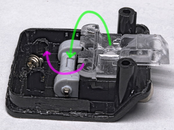
The locking action is achieved through the interaction of three components. The cap provides a structural foundation and two notched posts on the left side for the plastic spring to slot into (purple arrow). The two prongs are injection-molded into a single unit with the cam detents and top of an internal contact showing at the bottom. Then, there's a plastic spring with the cam follower molded into it on top (green arrow) providing the snap action.
It's a simple and effective solution.
MORE: AmazonBasics ABHT1208TC Tear-Down
MORE: CyberPower EC350G Tear-Down
MORE: How (And Why) We Test USB Power Adapters
First Peek At The Internal Construction
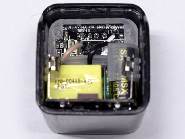
Nothing is left to chance with internal packing and clearances. The low-voltage output PCB is held in place vertically at the top by a plastic frame, which shields it from high-voltage components in the bottom half and maintains the spacing for the two contact arms to the prong pins. Very little space appears to be wasted, judging from this angle.
MORE: AmazonBasics ABHT1208TC Tear-Down
Get Tom's Hardware's best news and in-depth reviews, straight to your inbox.
MORE: CyberPower EC350G Tear-Down
MORE: How (And Why) We Test USB Power Adapters
Welded Shut
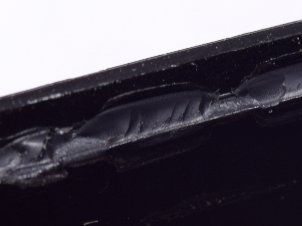
Based on how small pieces of plastic were ripped off either side of the seam at different locations, I suspect that solvent-based welding was used here.
At this point, I’m just glad I managed to pop the PA-U32 open with only a few scuffs and a slightly bigger crack at the LED hole.
MORE: AmazonBasics ABHT1208TC Tear-Down
MORE: CyberPower EC350G Tear-Down
MORE: How (And Why) We Test USB Power Adapters
Assembly – Back
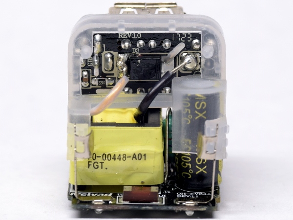
With the whole module now out of its enclosure, we can see the neat little package in more detail.
Up top, we have the output board sitting inside a plastic frame, which provides separation between the board and transformer underneath.
Only those two double-insulated wires connect the output board to the rest of the adapter. They shoot straight up from the winding to the output board.
MORE: AmazonBasics ABHT1208TC Tear-Down
MORE: CyberPower EC350G Tear-Down
MORE: How (And Why) We Test USB Power Adapters
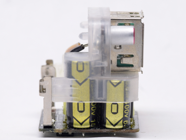
Assembly – Left Profile
On the left profile, you can see how the plastic frame covers both input capacitors and provides a "shelf" under the USB connectors to separate them from the transformer underneath. Should anything catastrophic happen on the high-voltage side, there is very little chance of electrical current finding its way to the output board with so many barriers and so much distance in-between.
To the left, you can also see one of the plastic tabs going inside a contact arm.
MORE: AmazonBasics ABHT1208TC Tear-Down
MORE: CyberPower EC350G Tear-Down
MORE: How (And Why) We Test USB Power Adapters
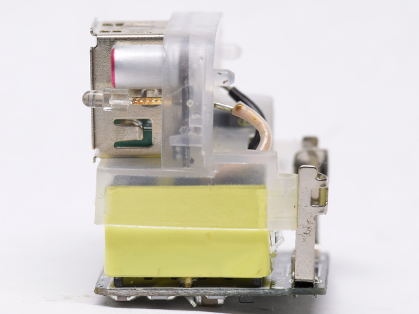
Assembly – Right Profile
The opposite view prominently features the transformer, which occupies most of the adapter’s depth and half of its height. In front of the USB connector, below the filter capacitor, we also spot the easy-to-miss power indicator LED.
MORE: AmazonBasics ABHT1208TC Tear-Down
MORE: CyberPower EC350G Tear-Down
MORE: How (And Why) We Test USB Power Adapters
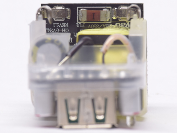
Assembly – Top
Viewed from up top, the transformer appears to account for roughly half of the high-voltage board's space. Its only other major visible component, aside from the capacitors, is a surface-mount input fuse.
MORE: AmazonBasics ABHT1208TC Tear-Down
MORE: CyberPower EC350G Tear-Down
MORE: How (And Why) We Test USB Power Adapters
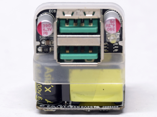
Assembly – Front
From the front, we can see that the input capacitors come from Asia’x. These are poorly documented. Hiding between the capacitors and transformer is a small MOSFET, which does the heavy lifting.
Again, there's not much space going to waste.
MORE: AmazonBasics ABHT1208TC Tear-Down
MORE: CyberPower EC350G Tear-Down
MORE: How (And Why) We Test USB Power Adapters
MOSFET
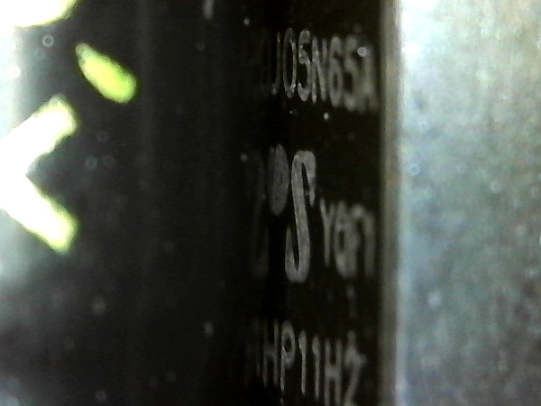
Based on the partial model number visible from such a steep angle, along with my search results for "05N65," the power switch appears to be a TO-251 N-channel MOSFET rated for 5A and 650V.
None of what I found matched the logo in the middle. But among the manufacturer specs I looked at, RDSON ranged from 0.9Ω to 2.4Ω.
MORE: AmazonBasics ABHT1208TC Tear-Down
MORE: CyberPower EC350G Tear-Down
MORE: How (And Why) We Test USB Power Adapters
Assembly – Bottom
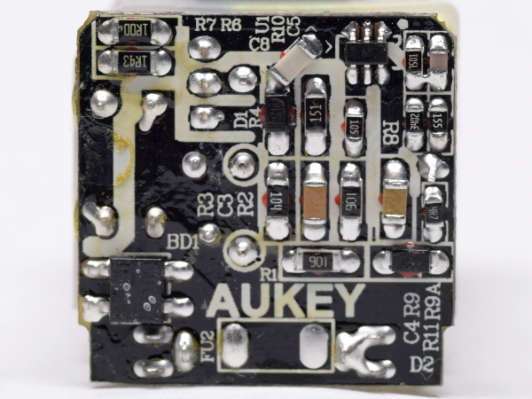
With most of the high-voltage board’s top occupied by the transformer and electrolytic capacitors, much of its magic gets shuffled to the bottom in surface-mount flavor. The two-prong contact arm resides at the bottom of the board, its right-most prong going through the fuse before reaching the rectifier in the bottom-left corner. DC voltage then goes through the electrolytics along the left edge, the primary-side sensing resistor, mains-side switch, and transformer primary in the top-left corner. The other components are start-up resistors, snubbers, and primary-side sensing circuitry for the SOT-363 controller in the top-right corner.
After seeing the generic ETL listing, I am a little surprised to find a custom-branded PCB in there.
MORE: AmazonBasics ABHT1208TC Tear-Down
MORE: CyberPower EC350G Tear-Down
MORE: How (And Why) We Test USB Power Adapters
-
d.schrei3er About the "cracks" around the LED hole: three flowsthey are "knit lines" caused by the flow of plastic into the mold. Its pretty obvious that the plastic converged at the LED hole from 3 fronts: over, under, and in between the two USB holes. By the time the plastic reaches that location it has cooled enough (at least at the surface) that the 3 flows are not hot enough to fully weld. You comment that it seems solid, which it most likely is, and the obvious knit lines may merely be a cosmetic surface defect caused by minimising mold temperature, pressure, and cycle time past the bare minimum. I.e.: there's a reason this device only costs $9.99.Reply -
mikewinddale Thanks for doing these teardowns. I own two Aukey products: a 20,000 mAh battery pack and a Quickcharge charger. This teardown gives me some extra piece of mind.Reply -
Farrwalker This type of article is interesting to me. So may USB chargers out there and so little objective information.Reply
I recently bought three of Quick Charge 3.0,Onlier 30W Qualcomm USB Wall Charger 3-Port USB Fast Travel Adapter.
It is supposed to have the following features:
Quick Charge 3.0
4x faster than conventional charging. Charge a compatible mobile phone up to 80% in 35 minutes.
Charging Quicker, Using Safer
Protect your devices against excessive current, overheating, and overcharging; avoid any security issues happening.
Qualcomm Quick Charger 3.0 Specification
Input:100v-240VAC 50/60HZ.
Output :
1:DC3.6v-6.5v/3A Dc6.5v-9v/2A Dc9v-12v/1.5A
2:DC5V2.4A max
3:DC5v 2.4A max -
Xajel I have a very good experience with AUKey in their cables, I use Type-C ( with QC 3.0 phone and charger ) and Lightening and both are awesome.. I had one charger before which was working flawlessly with all my devices.. but I lost it somewhere...Reply
For me, AUKey, Tronsmart, Choetech & UGreen are good Chinese brands that worked hard to distinguish themselfs from other cheap makers... -
Lutfij A very nice read! I'll relay the info to my little brother who is an avid user of smart phones and tends to go through USB chargers like the wind :PReply -
Daniel Sauvageau Reply20664608 said:Nice. Could you do the same for Ugreen 17W 3.4A?20665135 said:Yeah ! me too, Ugreen. I have the CD132 dual USB 30W Quick Charge 3.0 but any will do.
Glad you found it useful. I'll put Ugreen on my watch list for when I run low on my current stock One problem with buying stuff for future articles so far in advance (and without even knowing beforehand if the topic is going to be a hit or a miss to justify having so many samples ready to go) is that much of it may be gone from the market by the time I get around to it.20666135 said:Thanks for doing these teardowns. I own two Aukey products: a 20,000 mAh battery pack and a Quickcharge charger. This teardown gives me some extra piece of mind.
That sounds plausible. I don't buy the cost-cutting argument though: you can change where flows meet by adding an extra injection port or widening an existing port, adding/widening/closing vents, making runners slightly deeper, etc. all of which adding very little cost. If $2 adapters can achieve visually defect-free glossy finish, a $10 one should easily be able do the same. Granted, most of the cheapest adapters have a simpler shell with only one USB-A hole in it which makes it more difficult to get it wrong. With only one unit in my inventory though, the surface defect could be an exception rather than the norm.20665605 said:About the "cracks" around the LED hole: three flowsthey are "knit lines" caused by the flow of plastic into the mold.
Chrome? I had issues previewing the article on it too, had to read it with Edge.20667527 said:No images are showing.
