Build Your Own (Physical) 3D Models
Milling Preparations: MS DOS Used
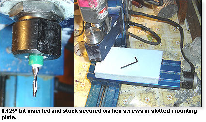
A piece of poly foam stock has been cut to proper dimension reflecting the size of the model. The stock is secured along the X/Y axis using T-Lines that are cut into the mounting plate of the mill. Hex screws are fed into metal braces held by the T-Slots, and tightened and advanced tightly to the stock boundary. Since our first pass is going to be a roughing pass, the 0.125" end bit has been mounted in the chuck.
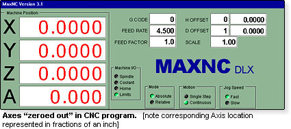
Now that the stock is secure and the proper bit is in place, the next step is to "zero out" the axes, which means placing the physical bit location at the correlating origin point of the GCode file. This is done by manually jogging or transiting along each respective axis until the bit reaches the "zero point" of the model.
The CNC controller being used runs "old school": it utilizes a parallel interface to the machine and runs under MS-DOS, which allows faster native access to the port. Even though the machine is running Windows XP (mostly for networked file transfer) I've created a boot disk with various .BAT instructions to create a virgin DOS environment when the CNC machine is used. A speedy computer is not necessary for the actual transfer of the Gcode; in fact, many people mill fantastic products on antiquated 486 systems, or even older! Most of the need for a fast graphics card or processor comes in the creation and visualization process used for the model and creating/simulating the GCode.
Get Tom's Hardware's best news and in-depth reviews, straight to your inbox.
Current page: Milling Preparations: MS DOS Used
Prev Page Prototype Molding Vs. High Volume Production Next Page Let's Mill It!
