How (And Why) We Test USB Power Adapters
Jumping Gaps
What is all that craziness about high voltage and hipot testing? Do a quick search about how AC adapters can potentially kill you and you’ll find a plethora of stories on the topic. In 2013, a sharp rise in the number of people reporting shocks from using their iPhone with unofficial adapters drew attention to the subject, but not in time to save Australian nurse Sheryl Aldeguer from death by electrocution in April 2014.
Given how ubiquitous those adapters still are, I am surprised that USB electrocution reports appear to have dried out by 2015. Has generic adapter safety really improved this much or did the world get luckier? Are the adapters still as deadly as ever, but partially mitigated by device manufacturers no longer exposing conductive surfaces connected to the USB shield or power? Whatever the case may be, for electrocution to occur, current must find a path from the power outlet to the USB adapter’s output, through the user and then back to ground or neutral. For that to happen involves some form of dielectric breakdown, component failure, manufacturing defect, or contaminant allowing current to cross isolation boundaries.
How much voltage do you need to jump a gap? Multiple variables play into this, the three most important ones being atmospheric pressure, gap width, and the dielectric. According to Paschen’s law applied to ambient air (mainly nitrogen), the “minimal gap voltage” is 327V at 7.5µm, which should make it theoretically impossible for normal AC line voltage to jump an air gap of any meaningful length. A smaller air gap than this isn’t possible. Below that distance, there are so few gas molecules between electrodes that most electrons leaving one electrode will reach the other without ionizing any molecules, which means no spark.
Here, I am attempting to demonstrate this gap with a more generous 610VAC, and by the time I get my tiny specks of light between wires, the wires look like they are touching to the naked eye. At more macroscopic gap widths, air has a breakdown voltage of approximately 3kV per millimeter using spherical electrodes. That can drop as low as 1kV per millimeter between sharp points and even lower when using thermionic or radioactive materials.

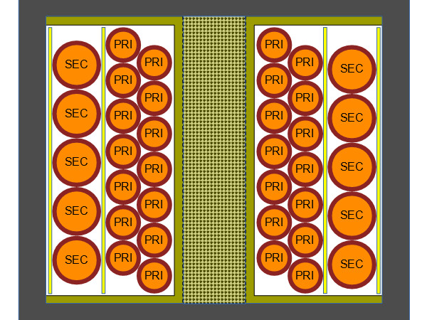
If it is so difficult for household voltages to cross air gaps, what's the problem? To put it simply, there is a handful of areas where something other than air stands between mains voltage and outputs, one of those key areas is the transformer, which consists of at least one primary winding, at least one secondary winding, often other windings, some form of additional insulation tape to prevent winding-to-winding shorts, a coil former to wind the transformer on, and the ferrite core.
Looking at the drawing, you can see that only two things are preventing the primary from shorting to the secondary: insulation tape between windings, drawn as yellow, and the wires’ own insulation, drawn in red, usually a thin enamel layer. Under normal circumstances, where air is the weakest dielectric between conductors, anything short of outright missing insulation allowing physical contact would be good enough to prevent electrocution. However, that assumption breaks down after the first breakdown.
In the (not always) hypothetical case where insulation between windings is torn, melted down, burnt, outright missing, or bare enameled wires cross each other on their way from the winding to terminal pins on the coil form, how much protection does the wires’ enamel coating provide before it fails? I twisted two pieces of #32 magnet wire scavenged from a small audio transformer together, hooked them up to my high voltage transformer and dialed the voltage up with my variac until either a spark appeared or the output voltage collapsed from a short. In this instance, failure in the form of a tiny speck, circled in green, occurred at 1000VAC. That's insufficient to prevent possible damage from static discharges on its own, and could be low enough to let a power line surge through if the output is connected to a grounded device. In other words, you don’t want enamel to be the only thing separating you from mains voltage.
Get Tom's Hardware's best news and in-depth reviews, straight to your inbox.
How much extra protection does having tape or some other barrier between transformer windings and wires grant you? To find out, I stuck one layer of generic polyimide tape on the inside of a power supply’s steel cover acting as one electrode, laid one piece of enameled copper wire on top, then used a second piece of tape to hold the wire flat against the bottom layer. As before, I cranked my high voltage up until failure occurred and my tape sample failed at 4170VAC. Once the tape was compromised, voltage across the fault dropped to 315VRMS. After subtracting the air gap voltage equivalent to the enamel and tape thickness, we should be left with roughly 3500VAC directly attributable to the tape itself, which we can further round down to 3kVAC to be on the safe side. Put a minimum of two layers of tape between windings to account for possible microscopic defects in the tape and we should realistically expect properly made transformers to withstand 4kVAC between primaries and secondaries.
Since failure occurred at the cut wire end, I repeated the test by bending the tip away from the bottom to determine how much of an impact the sharp end and exposed copper may have had on the first result. During my second test, I observed a flurry of failures along the whole wire length at 4300VRMS, confirming that the cut wire end had minimal impact on the first result.
Once sufficiently high voltage is applied to a dielectric, causing a breakdown, some of the materials along the path burn and sputter, further contaminating the track with chemical byproducts that may increase conductivity and lower breakdown voltage with each event. This is called a tracking or creepage failure. To illustrate what a tracking failure looks like and how it may progress, I set two large washers 50mm apart on a piece of pine wood, cranked my high-voltage transformer to 3800V, and used some tap water to trigger failures.
While clean and dry, wood is just about as good an electrical insulator as air. It does not fare so well once it's wet, though: minerals and chemicals in the wood provide plenty of ions to make the water and wood conductive. Electric arcs mainly along the grain char the wood and form carbon tracks that eventually bridge the gap between the two washers.
What I just did there was effectively a low-energy version of a Lichtenberg figure. A similar process can happen over a longer time span on or through any substrate with repeated static discharges or power line surges progressively burning paths between points.

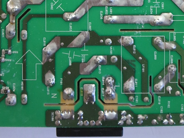
The only way to protect transformers, circuit boards, and their components against tracking and dielectric breakdown failures is having sufficient insulation between windings, leads, and traces to force excessive floating voltages to discharge in a controlled and hopefully safe manner at designated locations, such as a spark gap on the board. You can see a combined example of spark gaps across an anti-tracking slot at the bottom of the picture above. The spark gaps in this instance come in the form of toothed pads for the IEC connector’s hot, neutral, and ground pins. On circuit boards, anti-tracking slots between high-voltage pads, spark gaps, and unrelated traces are used to increase the creepage distance (the shortest distance current can take over a solid between two points) to mitigate the effects of surface contamination and reduce the likelihood of tracking between those points. Since the path across the spark gap is much shorter than the path around the isolation slot, sparks will jump the gap instead of tracking their way around the slots, rendering tracking-related failures highly unlikely.

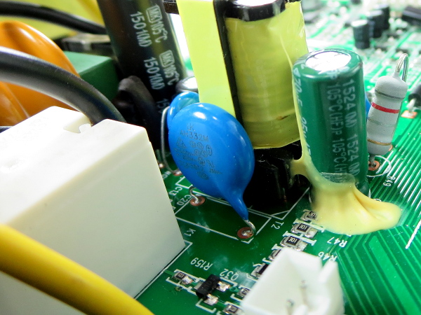
One last area where I expect many generic adapters to fail is their Y-class capacitors, or whatever they may use instead. What are Y-class capacitors for? The sandwiched windings within a transformer act as a parasitic capacitor, which adds common-mode noise to its output windings that radiates through any external devices connected to it. To mitigate this noise, a return path must be provided to let the common-mode current coupled into the secondaries return to the primary side. Since the capacitor serving that function bridges isolated output to mains, regulations and certifications require it to be an explicitly safety-rated type designed to fail open-circuit and withstand the worst possible potential differences that can be reasonably expected to occur in the field. In typical consumer equipment, Y2 capacitors are the most common type used for this purpose, and proper Y2 capacitors (usually chubby blue bobs across the isolation boundary near a switching power supply’s transformer) are rated to withstand 5kV. In knock-off adapters, you may get a regular ceramic capacitor not even rated for 1kV, a suspiciously thin and tiny generic blue thing that doesn’t look right, or nothing at all.

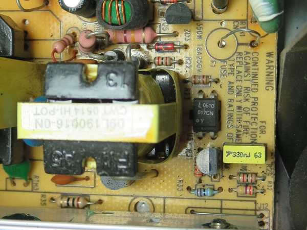
While optoisolators like the ubiquitous 817 technically straddle the boundary between mains and user-land, they're handy specifically because there is no electrical path within the package between the two sides. What's more, I do not remember ever hearing of similar optoisolators failing in such a way as to bridge outputs to mains.
With generic Chinese device manufacturers ordering generic parts from equally generic Chinese parts suppliers, fake or sub-par components are always a possibility. However, I strongly doubt that a manufacturer willing to stoop so low would bother with the cost of the extra support components compared to reusing the switching regulator’s bootstrap winding as feedback instead. Since even the wimpiest optoisolators I have seen are rated for at least 3000VAC, I would be really surprised to see a genuine one fail at merely 1500VAC.
By the way, yes, that’s a steel tack in place of F1. I still haven’t gotten around to “properifying” my SL300 and AR300 repairs with parts that fit better and legit replacements for parts I didn’t have on-hand at the time. I did order and receive those parts over a year ago, though.
MORE: Best Deals
MORE: Apple 5W Adapter Knock-offs: The Colorful A1265 Tear-Down
-
eenoram Love the article but the embedded videos arn't working across 4 different up to date browsers running with or without adblocker. Bummer!Reply -
berezini looks like toms doesn't have anything else to write about so they re-write old articles a month or two old to the same conclusion.Reply -
Daniel Sauvageau Reply
The A1265 look-alike story from last month was meant to come out after this one but due to some scheduling weirdness, they got swapped and as I wrote in comments to the "first" story, the set of fake A1265s used for the first tear-down (and also to demonstrate the point of this series which was intended to start with "how we test"), there will be a bunch more to come in the future. The ending was intended to be a teaser (and somewhat of a spoiler) for the first tear-down, which is why my preview here stopped at the first failure. In the actual tear-down, I cleared each successive failure until the adapter was either dead, destroyed or what remained of it passed isolation withstand.20619893 said:looks like toms doesn't have anything else to write about so they re-write old articles a month or two old to the same conclusion. -
bit_user Thanks again, mate. Looking forward to some good recommendations.Reply
How can we help fund your efforts? If your recommendations save me even one expensive equipment failure, it'd be worth a lot. -
bit_user Reply
So you read all the CES coverage? I still have some bookmarks to check out, as I couldn't keep up with it.20619893 said:looks like toms doesn't have anything else to write about
IMO, it's understandable if they & the industry are having a bit of a quiet week (meltdown/specter aside), after CES. Most companies with anything to announce did it at CES, so the newswire is definitely going to be quieter this week. -
Daniel Sauvageau Reply
Recommendations-wise, I have one coming 2-3 stories from now which I sent in for editing last week and costs ~$10 and passed all of the tests I threw at it. It did have one potential manufacturing-related safety flaw in it but I'd need multiple samples to determine whether I got unlucky or should flag it as a significant concern.20621006 said:Thanks again, mate. Looking forward to some good recommendations.
How can we help fund your efforts? If your recommendations save me even one expensive equipment failure, it'd be worth a lot.
As for how to contribute, I'm open to suggestions if there is enough interest in doing so. -
chaz_music Something you should add to this: I have noticed many AC adapters being sold on Newegg, Amazon, and eBay that don't have a UL or ETL mark. That means that they did not go through either those agency's safety testing and analysis. Many of the things you found would be caught by UL, especially the shock and fire issues.Reply -
Daniel Sauvageau Reply
Marks are only as trustworthy as the supply chain between the buyer and manufacturer is. You can't trust any marks on stuff from generic off-shore sellers who have no domestic liability as the seller has very little incentive to ensure that marks on items are genuine. By the time people realize that they got a fake or fraudulent item (that looked and behaved roughly like the real thing), the feedback period on the sale is often expired and the original listing long gone.20622599 said:Something you should add to this: I have noticed many AC adapters being sold on Newegg, Amazon, and eBay that don't have a UL or ETL mark.
The first line of defense against no marks and fake marks is buying from a domestic source where liability falls onto the vendor/importer when the manufacturer is out of legal reach.