TFT Guide Part 3 - Digital Interfaces
Advantages And Disadvantages Of Digital And Analog Interfaces
| Header Cell - Column 0 | Digital Control | Analog Control |
|---|---|---|
| Advantages | No signal losses due to DA and AD conversionGeometry, clock and phase settings unnecessary, therefore simple to useLower costs as less electronic circuitry required | Compatible with standard VGA boards on a broad installed PC basisNot necessary to purchase a new graphics board |
| Disadvantages | Currently three standards (P&D, DFP and DVI)Low availability of models with digital interfacesRequires graphic board with digital output | Clock and phase of the TFTs must be synchronized with the analog signal to avoid pixel jitter, which is a relatively complex issueCables sensitive to external influencesHigh cost of signal conversion inside the displayUpgrade to digital interface not possible |
Table 1: Advantages and disadvantages of analog and digital control
The following sections introduce you to the three leading digital interfaces.
A Little History - Or What Remained Of P&D
The Video Electronics Standards Association (VESA) is - to some extent - partly to blame for the multitude of different technologies as the organization failed to react to the requirements of the industry on time. Many companies started to undermine the authority of the association by forming interest party groups with the aim to set their own standards. Although VESA introduced its first version of the digital Plug-and-Display (P&D) standard in 1997, the specification missed the reality of the situation at that time by a long shot. For example, the digital connector was intended to be implemented in a type of multifunction connector, but no one was interested in this unwieldy component. Although it was possible to transfer digital and analog signals via P&D, the additional integration of USB and IEEE1394/Firewire signals made this solution virtually unusable in practice. None of the graphic board manufacturers wanted to invest in such an expensive connector.
What is the principle behind the transfer protocol? The magic word is Transition Minimized Differential Signaling (TDMS) - also referred to as PanelLink. The trick behind this is the fact that electronic disturbances always affect both lines of the Twisted-Pair cable and are therefore effectively filtered out. This technology remains practically insensitive to external disturbances.
Figure 1: The unwieldy and expensive P&D connector has 30 pins. The four pins on the right are used to code the functionality.
DFP - Digital Flat Panel Group
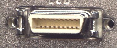
Figure 2: The 20-pin DFP connector (MDR20). The maximum resolution is restricted to 1280 x 1024 pixels.
The Digital Flat Panel Group was brought to life under the leadership of Compaq. The most renowned member of the DFP group is almost certainly ATI , who was one of the first companies to produce a graphic board with this connector. VESA has since adopted DFP as an interim standard. If you compare the features of DFP with those of P&D you'll hardly find any differences. DFP is basically a tuned-down P&D connector. The electrical specification is practically the same, except that the expensive special functions such as analog signals, USB and IEEE1394 are missing making it an inexpensive solution. The only disadvantage is that the maximum resolution is restricted to SXGA (1280 x 1024 pixels). Although DFP connectors are already be found on ATI's Rage Pro LT, Voodoo 3's 3500 and Number Nine's SR9 for example, the future of DFP is already preprogrammed. The restriction of the maximum resolution to SXGA will only ensure DFP connections a limited lifetime.
Get Tom's Hardware's best news and in-depth reviews, straight to your inbox.
DVI - Digital Visual Interface
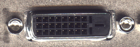
Figure 3: The 24-pin DVI connector can transfer digital and analog signals. The resolution is not restricted to SXGA.
The Digital Visual Interface (DVI) was developed by the Digital Display Working Group (DDWG). The lobbyists behind DVI include many companies that were originally involved in DFP. Although it has not been accepted as a standard by VESA, DVI has a very good perspective for the future because the digital transfer protocol is still TMDS (PanelLink). In comparison to P&D and DFP, which only have one link, DVI incorporates a second link, which doubles the maximum pixel rate. This allows resolutions over 1280 x 1024 pixels. A further advantage of DVI is the fact that analog signals can also be transferred. Therefore, older cathode ray tube monitors can still be connected if needed.
Current page: Advantages And Disadvantages Of Digital And Analog Interfaces
Prev Page Who's Leading The Race? Next Page Comparison And Summary

