How To Use Resistors in a Project
Resistance is futi… Voltage divided by Current
The maker toolkit has a core selection of essential maker tools. The tools that we can’t do any work without. Breadboards, soldering irons, LEDs are important, but resistors are the tiny components that projects depend on.
No matter what bord we choose, be it Raspberry Pi, Raspberry Pi Pico or Arduino, we need resistors to protect our LEDs, divide voltages and provide precise values for our circuits. But what do they do, why do we need them and how can we make sure we have the correct value? For that we need to do a little math, and consult a few datasheets.
In this reference we will explain what resistors are, what they do and tell you how to pick the correct resistor for your next project.
What are Resistors?
Resistors are components which introduce electrical resistance in a circuit. Typically they are used to reduce the current flow in a circuit, for example when used with LEDs they stop the LED from consuming too much current.
An LED without a resistor will burn itself out very quickly. Resistors can also be used to create voltage potential dividers, useful circuits that will reduce the voltage in a circuit. Every maker will have some resistors in their kits. They come in bandolier strips and can be bought in singular packs or in their thousands.
Why Do We Need Resistors?
The most basic use of resistors is to stop a component from consuming too much current. Take for example an LED (Light Emitting Diode). LEDs are designed to pass current in one direction and produce a small amount of light as they operate. If we give LEDs as much current as they want, the LED will light brightly but soon burn out. In some cases we can give it too much current at once, causing the LED to “pop” and then die.
We can use the following calculation to determine the exact resistor value.
Get Tom's Hardware's best news and in-depth reviews, straight to your inbox.
R is the resistor value, Vs is the supply voltage, Vf is the forward voltage (the amount component needs), and If is the forward current.

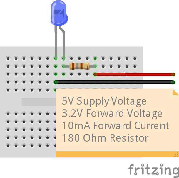
Let's put this into practice. We have a blue LED connected to a 5V supply. The forward voltage of the LED is 3.2V and the required current is around 10mA. So the calculation looks like this.
This means that the value of R is 180 Ohms. In the standard series of resistors we can use this exact value or we can choose a 150 or 220 Ohm resistor instead. For basic tasks, the exact value isn’t essential but when designing circuits for professional / industrial or high precision devices you will need to use the exact values. The exact values can be found in the components datasheet or on the product page from your chosen store.
For most hobbyist / maker applications we can choose the nearest value that we have. We often favor a 220 / 330 Ohm resistor for our LEDs.
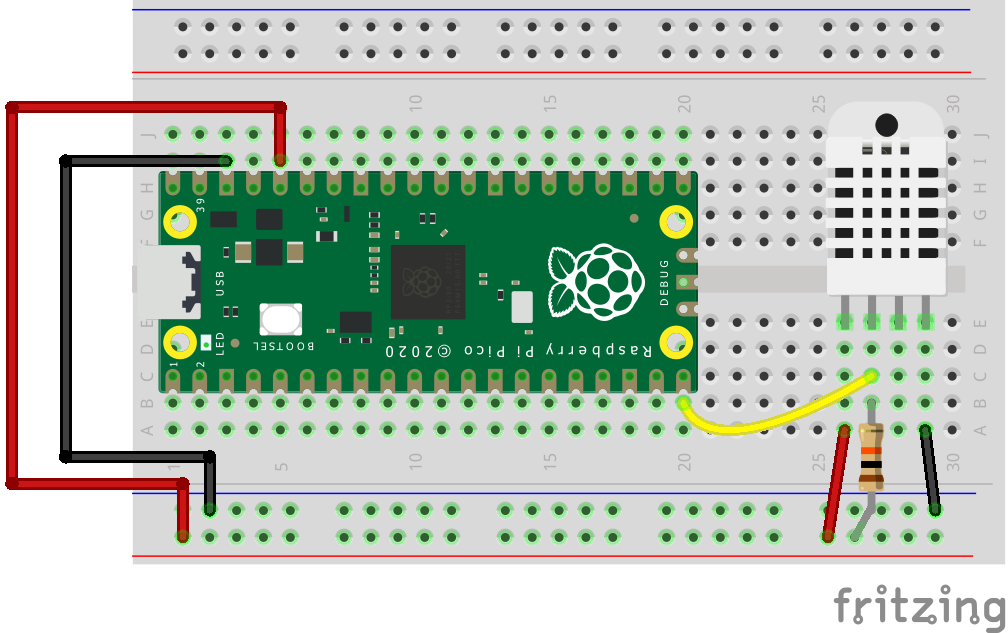
Resistors can also be used to pull up or pull down a GPIO pin. A pull up resistor will pull a pin high by connecting a voltage supply to a pin. A pull down resistor will pull a pin down to GND. We used a 10K Ohm resistor with a DHT22 temperature sensor to pull the data pin high using the 3.3V supply.
Resistors can also be used to drop voltages from one level to another. This is called a voltage divider and it is commonly used in potentiometers to vary the voltage.
To create a voltage divider we need to use this equation.
Vout is the voltage that we want.
Vin is the input voltage.
R1 is the first resistor’s value.
R2 is the second resistor’s value.
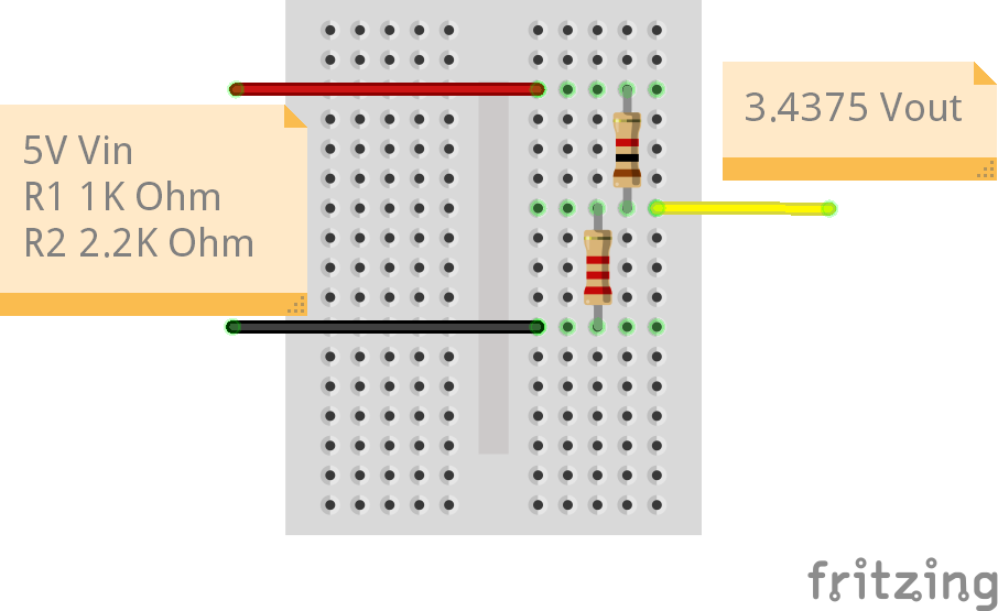
So, for our voltage divider we want to convert the 5V input voltage to around 3.3V. This process is commonly used when we need to change the logic voltage of a component, for example the HC-SR04. The HC-SR04 ultrasonic distance sensor originally used 5V logic, and so the echo pin, which activates when sound bounces off an object, will send 5V to the GPIO.
For an Arduino, this is ok. For a Raspberry Pi, it can damage the pin, or even the Pi. We’re using two resistors, R1 a 1K Ohm resistor (top) and R2 a 2.2K Ohm resistor (bottom) to create a voltage divider. The legs of R1 and R2 go into the same row of the breadboard. Into R1 we supply 5V and into R2 we connect to GND. Where the legs of R1 and R2 meet is the output voltage, which should be 3.4375V, well within the tolerance of the 3.3V GPIO.
The calculation works by adding R1 and R2 together (1000 + 2200 = 3200) then we divide the value of R2 by this (2200 / 3200 = 0.6875) and lastly we multiply by the input voltage (5 8 0.6875 = 3.4375V).
How Do I Choose the Correct Resistor?
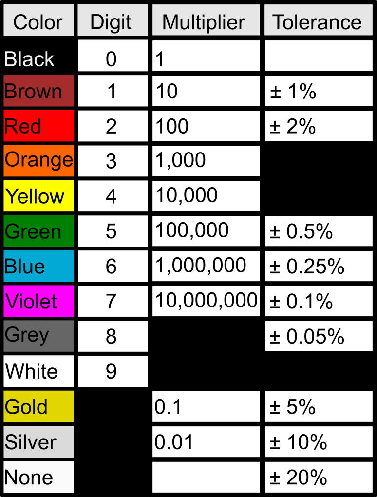
Resistors have color bands around their axis. We have a detailed article on how to decode resistor color codes, but below is a brief explanation that's suitable for your first project.
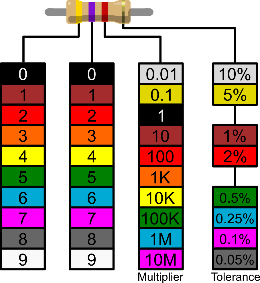
These bands are a code system that we can use to identify the value of a resistor. There are four, five and six bands but the most common are four. In fact the four band resistors are the easiest to read.
Let’s take this resistor as an example. The bands are printed to the resistor but the final band, tolerance, is printed on one of the “bulges” at the end of the resistor. We can see the first band is yellow and the second is violet. This gives us a value of 47. The third band is the multiplier, in this case red is 100. If we do the math, 47 x 100 = 4700. We have a 4700 Ohm resistor, generally referred to as a 4.7K Ohm resistor. The final band is the tolerance. Our tolerance band is gold which means we have a 5% tolerance, it could be 5% over or under the 4.7K Ohm value.
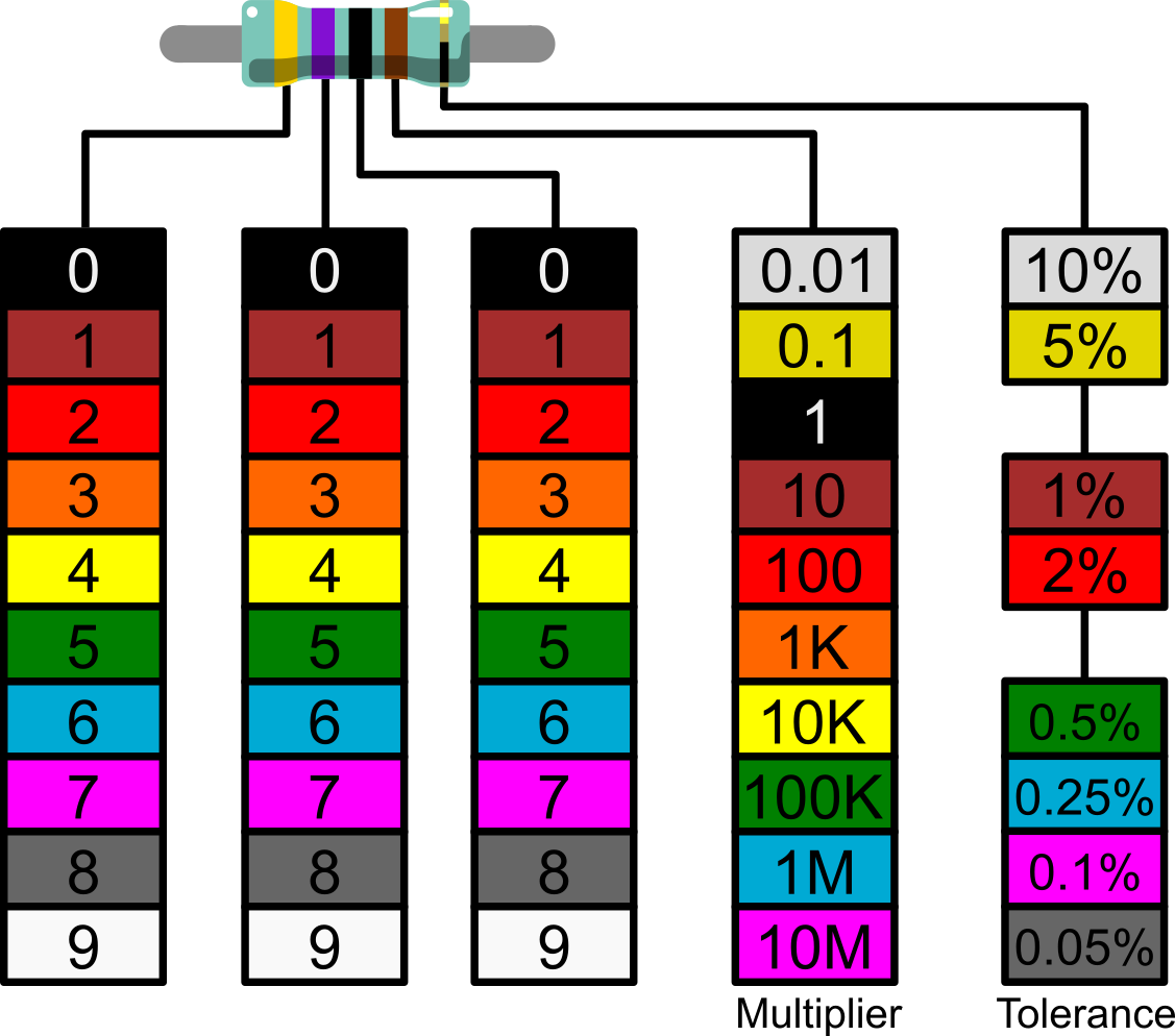
Five band resistors offer additional precision and use an extra third digit to dial in the precision. The same 4.7K Ohm resistor’s third band is now black, which refers to zero. The fourth band is the multiplier and the fifth is our tolerance.
This table provides a quick reference which can be applied to four and five band resistors.
Checking Your Resistors
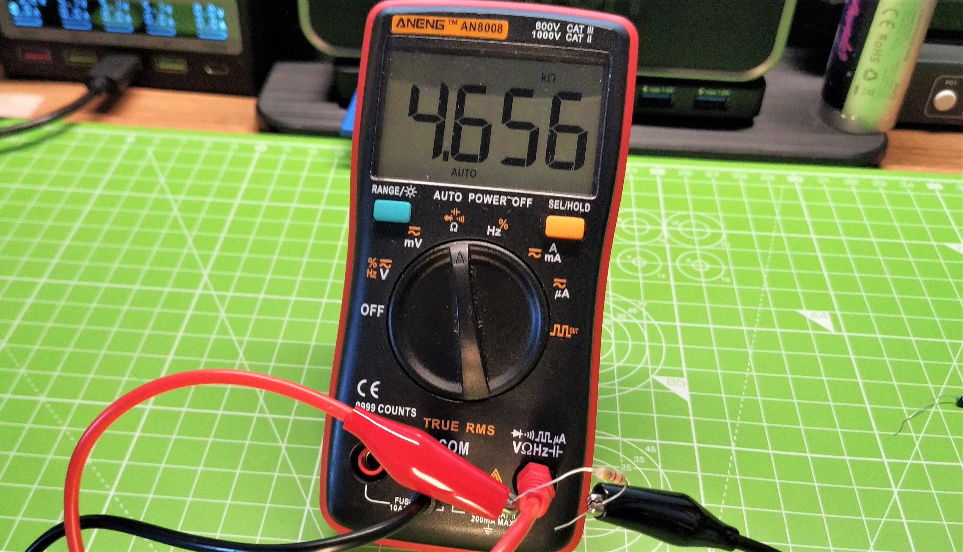
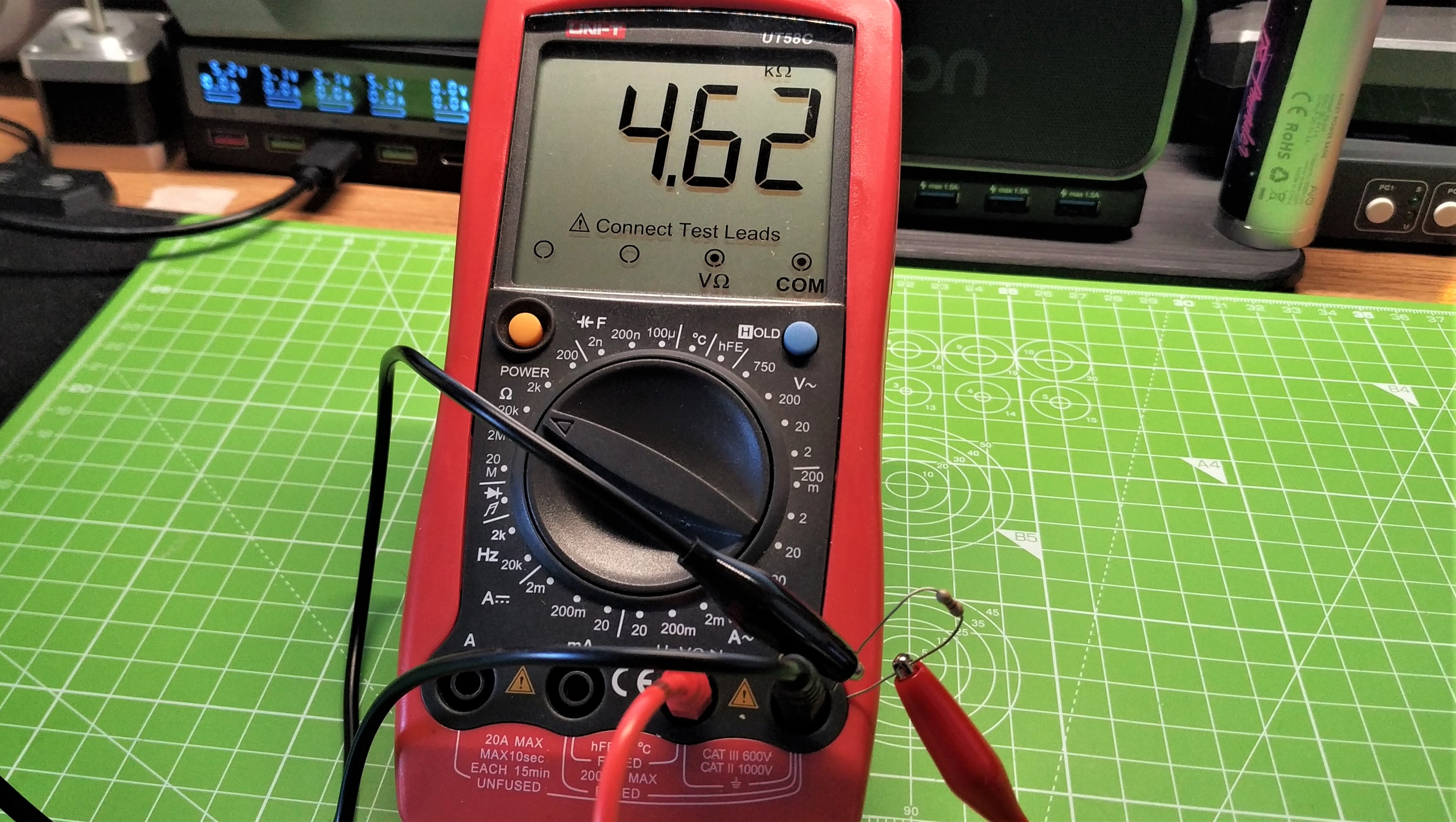
Sometimes it can be hard to correctly identify a resistor by its color code. It could be old, damaged or incorrectly printed. If that is the case then we can check our resistor using a multimeter.
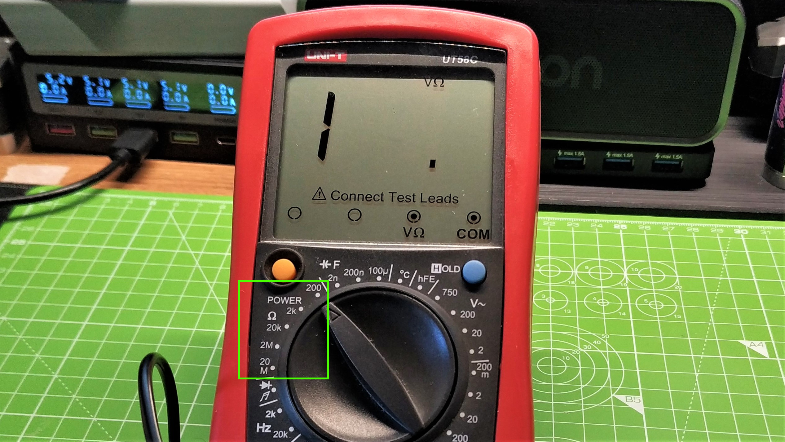
Multimeters are an essential tool for makers. Amongst other features multimeters can measure voltages, current, and check for continuity in a circuit. There are two common multimeters, auto-ranging and manual. Auto-ranging try to detect reading and put it into a range. For manual we have to set the range.
For Auto-Ranging Multimeters
1. Turn the dial to the Ω (Ohm) symbol and press the power button. Some multimeters will turn on when the dial is turned, while others have a power button.
2. Wrap one leg of the resistor around one probe. Resistors do not have a polarity so we can connect either leg to the probe.
3. Wrap the other leg around the remaining probe.
4. Read the value from the screen. Give it a few moments to settle before taking a reading.
For Manual Multimeters
1. Turn the dial to the Ω (Ohm) symbol and select the lowest range. Press the power button.
2. Wrap one leg of the resistor around one probe. Resistors do not have a polarity so we can connect either leg to the probe.
3. Wrap the other leg around the remaining probe.
4. Read the value from the screen. Give it a few moments to settle before taking a reading.
5. If the reading states OL or garbled, go up one range until you see a stable value. This is the multimeter trying to tell us that our reading is out of range, normally higher than the manual setting we have used.

Les Pounder is an associate editor at Tom's Hardware. He is a creative technologist and for seven years has created projects to educate and inspire minds both young and old. He has worked with the Raspberry Pi Foundation to write and deliver their teacher training program "Picademy".
-
punkncat I live near Atlanta, and there is almost nowhere left to find 'off the shelf' resistors of a wide variety any more. We work in fire safety, and even the supply houses for the alarm parts have stopped carrying them. We had a small locally owned place that closed last year, and with the past death of Radio Shack and more recently Fry's there is simply nowhere left to pick these up outside Amazon and such.Reply -
Johnpombrio I was repairing a $150,000 Hewlett Packard cable tester system for UL Labs. Sometimes it worked great after a calibration, sometimes it worked terribly and showed numerous erroneous results. After spending 2 days and umteen hours troubleshooting, I found that one of the two $200 "precision" 10-ohm reference resistors mounted on a board was, wait for it, 100 ohms. I noticed the markings and, remembering the resistance chart from school, figured out that the label on the board it was mounted on was wrong. I measured the reference resistors with a simple voltmeter and replaced the errant reference resistor. 6 engineers and I missed this simple error for weeks!Reply -
punkncat ReplyJohnpombrio said:I noticed the markings and, remembering the resistance chart from school
there was a simple sentence for recalling the color bands, but I can't recall it any more. I just use a meter or look it up at this point. -
Johnpombrio Reply
Working as a test and measurement repairman for HP for 25 years, I watched most of the boards in the instruments go from having discrete components and potentiometers to surface mount and analog to digital chips. Towards the end, swapping boards was really the only way to fix anything. Woe betides the guy trying to fix the very old stuff, like your building alarm/fire/intrusion systems, heh. It wasn't all roses back when there were electronic component stores around tho. The parts like resistors were mostly the most used values, usually tiny, and could not handle any sort of current. Fuses were really tough (remember fuses?) and for a long time I had a bin full of dozens of fuses of all sizes. Chips were pretty much non-existant except for hobby timers, some inexpensive A to D chips, and low-end CPUs. At least I was spared having to fix wire-wrapped boards as breadboards and circuit board kits were available when I first started. Nowadays, we are BLESSED with overnight delivery of pretty much anything you can think of for parts. No, the "good old days" weren't that great.punkncat said:I live near Atlanta, and there is almost nowhere left to find 'off the shelf' resistors of a wide variety anymore. We work in fire safety, and even the supply houses for the alarm parts have stopped carrying them. We had a small locally owned place that closed last year, and with the past death of Radio Shack and more recently Fry's there is simply nowhere left to pick these up outside Amazon and such. -
Johnpombrio Reply
Bad Boys Rap e Our Young Girls, But Violet Gives Willingly. Gawd, that just popped into my head when you mentioned it. I am sure there are some better PG versions out there!punkncat said:there was a simple sentence for recalling the color bands, but I can't recall it any more. I just use a meter or look it up at this point. -
punkncat ReplyJohnpombrio said:Bad Boys Rap e Our Young Girls, But Violet Gives Willingly. Gawd, that just popped into my head when you mentioned it. I am sure there are some better PG versions out there!
Lol, I think at this point in my life, when I have to learn something new, an older memory has to be ejected for it to take. -
digitalgriffin ReplyAdmin said:They cost less than 1 cent each, but humble resistors are an essential tool no matter what electronics you are building. In this reference 6hKT5juHjBn3qymNbofaEje we look at using them in projects, and how to identify the correct resistor for your project.
How To Use Resistors in a Project : Read more
One important thing is to "Know thy wattage" Resistors are rated in 1/8th, 1/4, 1/2, 1W+ varieties. If you pick the wrong one, your resistor can burn out. While 1/4W is more than sufficient for most applications, it might not be for all. For example, your pi/arduino might be driving a transistor/MOSFET which can carry a MUCH higher current load.
The equation to know here is VV / R. So if you have a voltage drop across the resistor of 10 V and a resistance of 20 Ohms, you get 1010 / 20 = 100 / 2 = 5 Watts of Heat. You would need a 5 Watt rated resistor.
Excellent Article.
For those looking for cheap parts: Amazon & AliExpress. For more reliable parts: Adafruit.com Mouser.com, and Digikey.com -
Reply
You forgot the rest...... "Get Some Now". That covers the tolerances :LOL:Johnpombrio said:Bad Boys Rap e Our Young Girls, But Violet Gives Willingly. Gawd, that just popped into my head when you mentioned it. I am sure there are some better PG versions out there! -
Olle P Reply
That's also one of my reflexions, together with the notion that unless you're operating with DC only one must also pay attention to any inductive impedance in the resistor. (Most) relevant to higher power resistors.digitalgriffin said:One important thing is to "Know thy wattage" ...

