Under The Kimono: Inside Intel's Hidden R&D
Introduction
We all know that Intel has a reputation for making stable motherboards. We also know that the company is two years into a long-range effort to make itself a top player in the enthusiast board space. Balancing stability with breakneck speed is no small task, and hardly anyone knows the lengths to which Intel goes in designing and redesigning components. Here at the Hawthorn Farms campus in Hillsboro, Oregon, a fleet of Intel teams and engineers pore over practically every aspect of motherboard design. When you check out a shiny new Smackover board, the number of man-hours devoted to making that board’s engineering as close to perfection as possible is staggering.
Intel invited Tom’s Hardware to take a rare look within the Hawthorn Farms facilites and show the world just what work goes into an Intel motherboard. Only a few months ago, we and every other press outlet were forbidden from setting foot past the lobby metal detector with a camera. So walk with us a bit and get a glimpse of the R&D fueling an Intel-based PC.
RF Testing Chamber
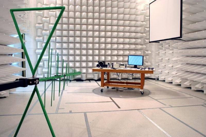
If you worry that your cell phone’s emissions might be baking your brain, you’ll love our first stop on Intel’s tour. This chamber is for testing PC radio wave emissions. Tests are done with both open- and closed-chassis scenarios. Such testing is required for FCC and CE mark approvals, required for electronic equipment in the U.S. and European Union, respectively. Just to be safe, Intel expects its platforms to surpass FCC specs by 4 dB.
More Emissions Testing
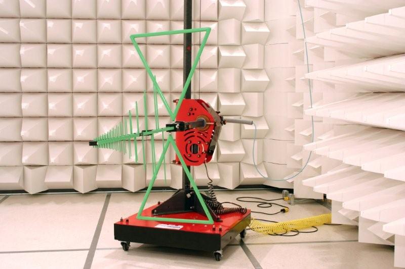
With this bad boy in your back yard, over-the-air HD channel reception should be a snap, no? OK, maybe not. This particular antenna tests emissions from 32 MHz to 2 GHz. Intel also uses a horn antenna able to test up to 18 GHz. The distance from antenna to system in this setup is three meters.
Peripheral Testing
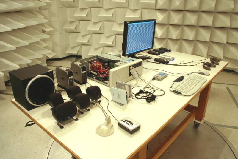
What self-respecting enthusiast doesn’t work or play without a barrage of peripherals? If you’re going to assess real-world emissions, you’ve got to bring on the phat 5.1 audio, a couple of gaming controllers, and a few dozen external hard drives. Interestingly, this test system was running a beta version of a refreshed Smackover—one of the first motherboards ever manufactured with zero halogens.
Next Stop: Acoustic Testing
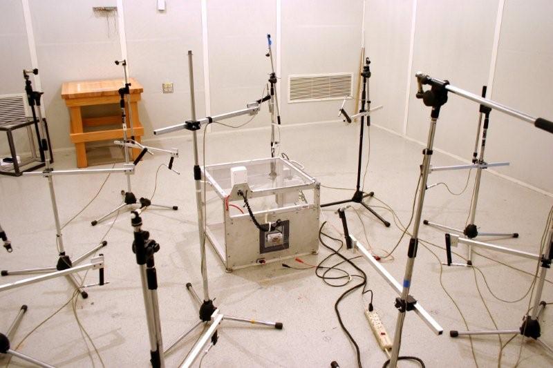
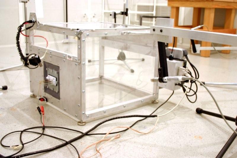
Next door, we have the acoustic testing room. With the door shut, the background noise level in the room drops to only 20 dB, giving the space an otherworldly, claustrophobic feel. An array of 10 microphones forms a sort of hemispheric dome around a test chamber positioned in the rooms exact center. Each mic is exactly one meter from this center.
Intel engineer John Blair explained to us that up until about 10 years ago, most acoustic measurements were done for sound pressure, which measures a pressure disturbance in the air influenced by the strength of the source as well as environmental elements, including the distance from the source to the receiver. One fan manufacturer might report a product having a sound pressure of 30 dB at one meter. A competitor might report a sound pressure of 29 dB but conveniently neglect to mention that testing was done at a distance of two meters. This is why much modern testing is done for sound power, which is an absolute value of acoustic energy emitted by a source independent of environmental factors. However, measuring sound power requires a microphone array similar to the setup you see here.
Get Tom's Hardware's best news and in-depth reviews, straight to your inbox.
A Little Acoustic R&D
The chamber shown here is used in measuring fan noise, as in a laptop or small PC. The gear includes an automated slide able to put various back pressure levels on the fan. This variable is then assessed with sound pressure measurements and airflow CFM (cubic feet per minute). With all of this analyzed together, engineers can work to optimize fan speeds for any given product. They can also conduct R&D for helping to develop new acoustic techniques, such as putting sheet metal around a laptop fan to help dampen noise output.
Replicating Human Ears
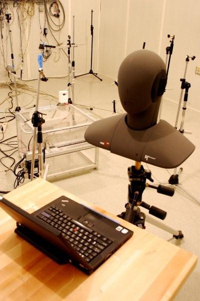
Sound pressure and sound power will only get you so far. They’re physical measurements, like temperature or electrical voltage, in a field that is often subjective. The human ear discerns some frequencies at louder levels than others. “Sound quality” is a third measurement that adjusts for these louder levels while also looking at values like tonality, sharpness, and roughness. Intel’s acoustic head system measures sound quality in much the same way as your own ears would. Not shown here is the plastic bracket used to position the head an exact distance from the notebook.
We shouldn’t convey that the acoustic room is all about fan noise. The findings made here can affect even the fundamental construction of a motherboard. On one case, designers had optimized a certain arrangement of resistors and capacitors on a motherboard for a given power situation. However, the signals flowed through the motherboard in just such a way that they caused the mother board to audibly vibrate—and thus required engineers to rework the board. A similar example is what Intel engineers sometimes call “singing inductors.” As you overclock and apply more power to inductors, they have a tendency to vibrate, sometimes audibly. Engineers such as John Blair spot these weaknesses during their tests and often work with parts vendors to find better insulating materials that won’t exhibit such flaws.
Extreme Environmental Testing
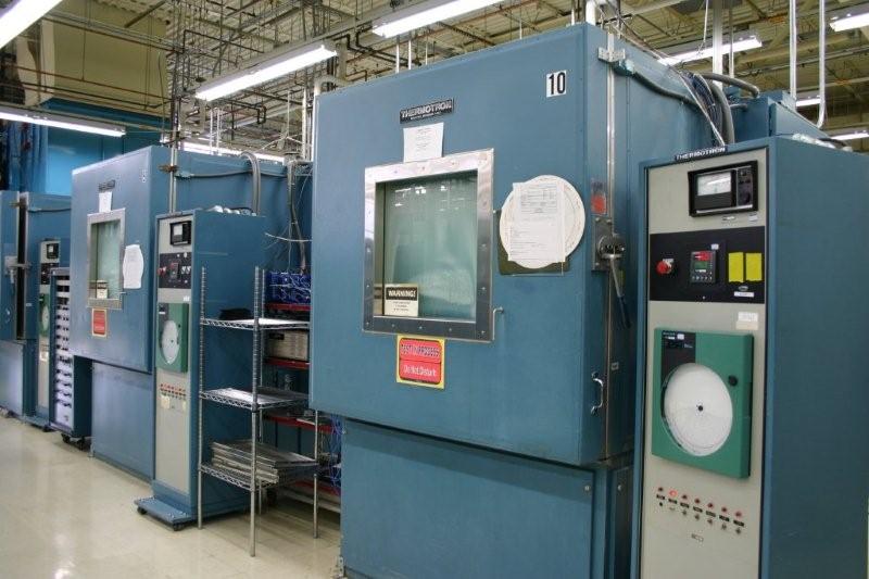
These Thermotron behemoths are environmental stress chambers for measuring performance under extreme temperature and humidity conditions. Each chamber measures 1.7 cubic meters, or 4' x 4' x 4'. Humidity can range from 20% to a sopping 95% while temperatures can span from -73̊ C to +177̊ C. As points of reference, the lowest natural temperature ever recorded on Earth was -89̊ C, and at 177̊ C, you could cook a pot roast. Speaking of which, considering bringing a lunch when you juice up the Thermotron, because its top temperature ramp rate is only 5̊ C per minute. In any case, designing a motherboard to run in a balmy Oregon afternoon is easy compared to having one sure to not fail in the icy Arctic depths or the sweaty interior of Ecuador.
Punishing Computer Hardware
Welcome to the shock and vibe room, hosted by dynamics process engineer Mike Williams. The point of this area is to test motherboards and see how much physical punishment they can take. If you’ve ever dropped a notebook from a table, accidentally kicked over a tower, or (shudder) shipped a system during the holidays, this is the room that helps to make sure your precious PC still works after the fact.
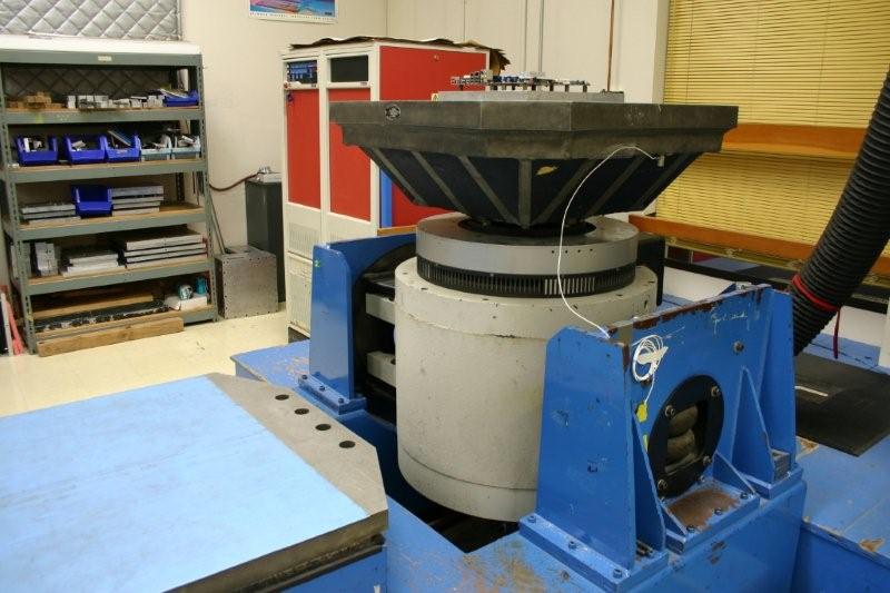
Believe it or not, this monster before you is about 25 years old. It’s essentially a giant, monophonic speaker. The table head weighs 400 pounds, and the platform can push with about 6,000 pounds of thrust, yielding about 20 to 25 G. Williams recalls visiting a similar machine at a facility in China and watching six men muscle the head across the room. This is why Intel installed a crane over the device. The black tube visible on the right wends up to a three-horsepower blower on the roof that sucks air through the speaker coil to keep it cool. There’s a similar machine in an adjacent room with about twice the capacity, although both machines serve equally well for their task.
Surviving Shipping
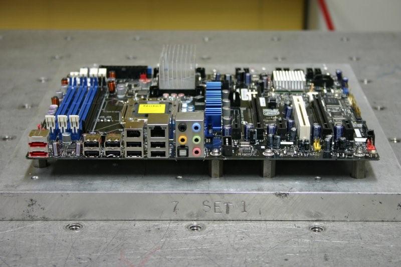
This shock and vibe machine is designed to test unboxed motherboards and examine how well they would survive being shipped in a chassis down gravel roads or over speed bumps. The victim mounts to a roughly one-inch thick plate dotted with ATX standoffs. The plate, in turn, mounts to the table head via a grid of screw holes. The motherboard vibrates for 60 minutes per axis of movement, and one hour of vibration is equivalent to about 1,000 miles in a truck. After all, no amount of electrical analysis and acoustic testing will matter if the board is busted when it reaches you. No industry standard exists for shock and vibe testing on motherboards, but research from this room at Intel often migrates into industry design guides.
Shock and vibe doesn’t merely look to see if traces will crack. You’ve may have noticed how capacitors are the most weakly mounted component on a motherboard. Wiggle one with your fingers a few dozen times and it will probably snap off. Shock and vibe can exert similar pressures on these components—so much so that Williams admits to seeing a machine on another site that couldn’t have its head removed because each hole in the table was filled with up to 10 capacitors. Similarly, it’s machines like this that exposed the weaknesses of the Z-clips that used to hold down heatsinks on components like northbridge chips. If you pulled on those heatsinks, the Z-clip would give a bit, and you could actually pull the heatsink away from the chip surface. Well, vibration could bounce the heatsink off the chip, and when the clip pulled the heatsink back, it would slam into the chip’s packaging.
Getting Hit With Gs
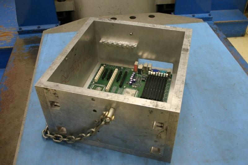
Of course, a motherboard isn’t much use if the stuff attached to it fails. Check out this test chassis, which also sits atop Intel’s massive shock and vibe machine. The shell weighs over 75 pounds. A motherboard mounts into the case on ATX standoff points, and cards mount onto the motherboard just as they would in a regular PC. The extreme thickness of the case serves to eliminate the flexibility you’d find in a normal sheet metal case, although Williams says, “If anything, it’s not thick enough.” In this test setup, the chassis gets hit with 25 G and the installed card with 50 G.
-
randomizer "In this test setup, the chassis gets hit with 25 G and the installed card with 50 G."Reply
Now that's quality control! -
Pei-chen Intel should move on to solid state (Japanese) capacitors. Better parts are better parts even if they are equally reliable in desktop environment.Reply
BTW, that “dark room” looks great. My office is too well lit.
-
enterco They may have good testing environment, but it seems that it's used only for 'select' motherboard/chipset combinations. For example, they don't test Core2 E7xxx CPU's in combination with x965 chipsets. Anyway, x965 boards should be able to use all Core 2 Processors with 1066 MHz.Reply
The conclusion: why bother to test and certify such an old motherboard chipset, as long there are so many testers out there?
-
curnel_D TheCapuletAhh, so this is what Toms got for this article: http://www.tomshardware.com/review ,2138.htmlProbably. Lol. But at least it was worth the cool look into Intel.Reply -
So, if Intel is so great then, what happened with the X38, X48, and X58?Reply
All three performance Intel boards "suck"......X975 was a great motherboard, however it has been very average since.....Has Intel ever thought to use a "solid capacitor" motherboard for the Extreme tine of boards? What gives with the Intel board? Anyway they need an enthusist level bios such as Gigabyte, Evga, Asus, or Dfi anyway.....Greatest Cpu and Chipset combination around, however the MOBO's suck wind.......Mr. Bad Kat......... -
Area51 ReplyThey may have good testing environment, but it seems that it's used only for 'select' motherboard/chipset combinations. For example, they don't test Core2 E7xxx CPU's in combination with x965 chipsets. Anyway, x965 boards should be able to use all Core 2 Processors with 1066 MHz.
The conclusion: why bother to test and certify such an old motherboard chipset, as long there are so many testers out there?
You sir are an idiot. -
enterco I believe you are wrong. There are few facts:Reply
1. Intel claims that their boards, specifically DG965OT can be used with 'Core 2 Processors with 1066 MHz FSB' (check this link)
2. Intel has made the Core2 E5xxx and Core2 E7xxx processors with lower FSB than E8xxx series, and these CPU's FSB are 1066, and 800 MHz, but their statement is that 45nm CPUs are compatible with 3x series chipset and later. Perhaps, a good reason to make these variants of Wolfdale is to make them available for older chipsets. But that's true only for other vendors' boards.
3. Intel's CPU compatibility tool claims that Core2 E7xxx (1066 MHz) cannot be used with DG965OT motherboard. This can be checked here.
4. Intel's support specialists from the agree that 'this combination is not tested'
5. Since I've asked them any details, Intel didn't update their DG965OT product specification page, and they did not include any statement regarding Wolfdale series Core2duo processors
Now, how can anyone explain that a motherboard which can be used with 'Core2 processors with 1066 MHz' cannot be used with Wolfdale-derived Core2s? The only answer I found is: they don't have enough resources to waste TESTING a combination whch seems to be valid; or they are interested in selling only the new motherboards, so a customer won't upgrade only the CPU.
Best regards, -
anonymous user enterco.Reply
Is your motherboard tested to work with every DDR3 memory vendor, every SATA HDD model, every PCI-e Video card? - NO -
As long as Motherboard and components meet common electrical specifications - they should work fine.
Functional testing usually covers some common components as a sanity check, but never every possible combination (that would be a waste of resources).
As long as motherboard and CPU meet common spec (and CPU is supported by BIOS) the combination should work, even if it is "untested"
In the end, that is the whole purpose of having electrical specificion for components.

