Let's Take a Trip Inside a Power Strip!
We count on power bars to protect our expensive PC hardware, and it's easy to take them for granted. Recently, one of our writers took an APC unit apart, though, and discovered some disturbing manufacturing work. Follow along as we dig into his findings.
Surprise!
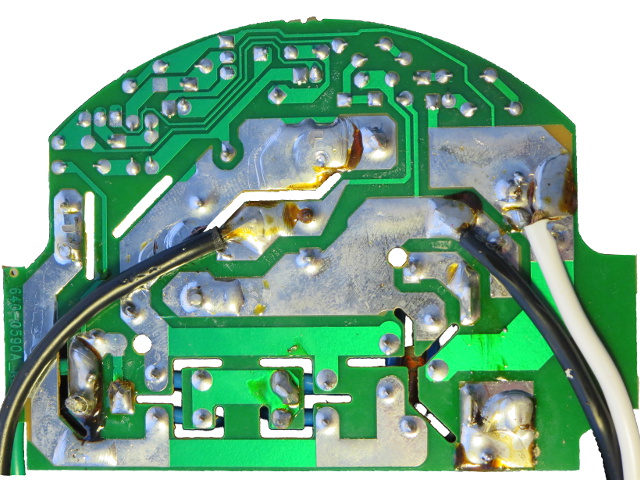
Here is that back side again. See anything odd? Aside from the sloppy use of soldering flux, there are at least three issue that stick out—or fail to, in this case:
- The ground wire shows clear signs of a cold solder joint (bottom-left).
- The neutral wire does not come through the PCB (just above dead-center).
- Neither does the live wire (bottom-right).
This is surprisingly sloppy assembly, especially considering those are the three most important solder joints in the whole contraption. They all got botched up in this particular unit.
The Not-So-Good
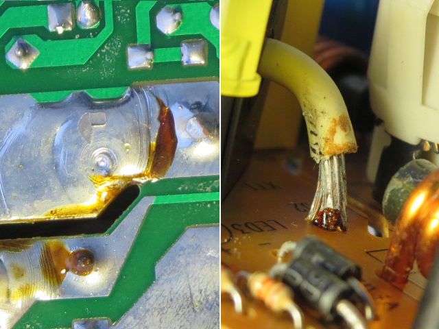
First up is the least-horrible of those bad connections: the neutral wire. It was clearly stripped long enough to go through the PCB and form a solid connection. But most of the exposed length is out on the PCB's component side, with little more than a dimple in the solder puddle from which it should have been protruding. This indicates that the wire was pulled back somewhat before the solder solidified or that the wire never got through (but did get hot enough to wick the solder off).
This isn't good. But at least the wire looks like it is thoroughly covered with solder, and it has the extra stiffness to prove it.
The Bad
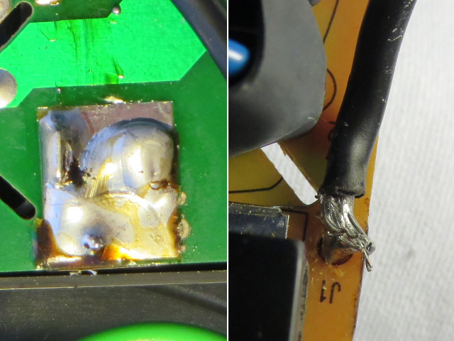
Second on my list of bad soldering jobs: the live wire. From the bottom of the PCB, it looks like a few strands are slightly protruding from the solder puddle. On the other side, the wire appears bridged to the PCB by a blob of solder coming through, with about half of the strands scattered around.
Again, you can only scratch your head and wonder how such a connection got past QC.
The Ugly
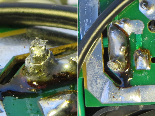
Third, there's the ground connection. And it takes the cake in my book. Of the three wires, this is the only one that passes cleanly through the PCB, yet it is also the only one that turned out to have a cold solder joint. Not enough heat was applied to the wire and solder failed to soak in.
Get Tom's Hardware's best news and in-depth reviews, straight to your inbox.
If you ever took an electronics class with soldering involved, this is exactly how your solder joints should not look—particularly if it is both performance- and safety-critical. Like, say, the ground in a surge-suppression device.
I suppose tidiness is not too important, as long as the solder joints are good enough to pass automated testing. But this doesn't exactly inspire confidence.
Busted!
Remember how this power bar is supposed to have a built-in 15 A breaker? Well, I got the inspiration for this story from an "accidental operational test" when a power supply I was trying to repair shorted out and blew up one of my SurgeArrest power bars.
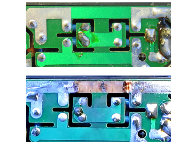
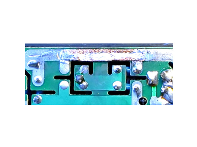
- Up top is what that PCB area normally looks like
- Down below, you see my busted power bar's PCB
The first thing I noticed upon opening the enclosure was two pieces of thin, mostly transparent, green, paper-like material rolling around. Looking at the blown trace of similar width, I concluded that the pieces must have been the solder mask covering the trace before it blew up.
All Patched Up
For the repair, I used a simple piece of solder wick to replace the blown trace, stiffened with solder to prevent it from flapping around and possibly shorting to the ground island in the middle. In the process, I started wondering why APC intentionally included such a weak point. Couldn't the company have simply soldered over those traces like it did almost everywhere else across the board? There are at least two reasons I can think of:
- An intrinsic fuse: if all other current protections fail to cut power, a blown trace definitely will.
- A sacrificial trace: In the event of a high-energy fault like a lightning strike, the MOVs will short enough current to ground to blow up the trace, thereby physically disconnecting the loads from the source. Because the arc this would create has to pass right next to the ground island, the arc should jump to that lower impedance path to ground, relieving the MOVs of their load.
Obviously, my repair voids those presumed extra safety features. But I'm still left wondering why bother with the cost of a built-in 15 A breaker if the traces within it blow up first when a faulty device is plugged in? Even the 6 A fuse inside the power supply doesn't have enough time to blow before the bar's trace. Does the built-in breaker even work? I had another go at fixing my defective PSU after repairing the power bar, and this time, the main breaker tripped first. The PSU's fuse burned out as well.
Juicy Lemons
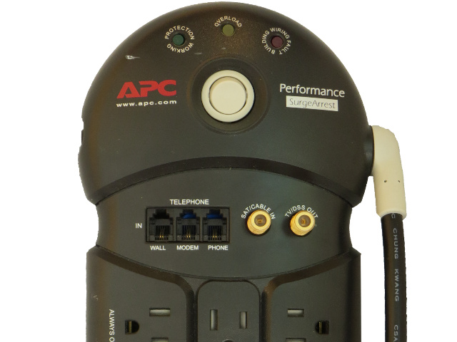
What could possibly go wrong in a name-brand power bar from a major manufacturer? A surprising number of things, apparently. This is what happens when quality control gives a sloppy manufacturing job a pass, thinking that nobody is going to look inside after the lid goes on anyway. The power bar with the blown trace was a P8T3-CN, and it had none of the sloppy wire soldering I saw in the PF11VT3-CN.
Originally, this story was supposed to be a simple look at what goes on inside of a quality power bar, but ended up turning into an unexpected cautionary tale—a reminder that even top-brand manufacturers have bad days on their assembly lines. After I finished the initial photo shoot, I jumped back in there and fixed the poor main cable solder jobs.
-
nukemaster Very surprised to see the inside of that(and I have 2 APC UPSs sitting in front of me.).Reply
Also never though of using the de-soldering braid as a patch :) -
Onus It seems to me that it might be worthwhile taking a look at the innards of some more of these. This doesn't give me any warm fuzzies about APC. What happened to pride in one's products?Reply
-
Kevin Harrelson Having a fuse in addition to a breaker makes sense. A breaker takes milliseconds to react, being a mechanical device. If the fit really hits the shan, a fuse can react MUCH faster than a breaker.Reply -
InvalidError Reply
Who knows. I'm sure most of this seemed like a good idea at the time.13941153 said:What happened to pride in one's products?
For the soldering, they probably put the units through automated testing and as long as everything tests ok, they send the units on their way - the ATE probably tests the live and neutral wires at 20A and the neutral with 100A pulses so in principle, if the ATE says everything is fine, the visual inspection becomes somewhat superfluous... it may not be visually pretty but as far as electrical testing goes, it appears perfectly sound.
But I agree about expecting better out of APC on that one. As noted in the conclusion though, the unit with the blown trace had none of the soldering issues found in the tear-down unit so the "lack of pride" was at least not systematic. -
arunphilip This is probably the first slideshow style of article that I totally enjoyed. Great photos, great writing, very educative!Reply -
edlivian i dont give a hoot about power savings anymore,intel has to start finding a way to gain 25% performance per cycle, or it will never become ideal to upgrade from sandy and ivy bridge i7'sReply -
10tacle ReplyWhat happened to pride in one's products?
It went out the window when the manufacturing went overseas.
-
qlum Reply
Who knows. I'm sure most of this seemed like a good idea at the time.13941153 said:What happened to pride in one's products?
For the soldering, they probably put the units through automated testing and as long as everything tests ok, they send the units on their way - the ATE probably tests the live and neutral wires at 20A and the neutral with 100A pulses so in principle, if the ATE says everything is fine, the visual inspection becomes somewhat superfluous... it may not be visually pretty but as far as electrical testing goes, it appears perfectly sound.
But I agree about expecting better out of APC on that one. As noted in the conclusion though, the unit with the blown trace had none of the soldering issues found in the tear-down unit so the "lack of pride" was at least not systematic.
Still regardless of if it passes electrical testing a bad solder may just die over time when the device gets bumped, moved or just gets older. It may pass the test when it was made but 10 years ahead it may become a very different story. I can tell you I do use things like this for more then 10 years because there is no reason to replace when it does still work.
This does make me wonder how my € 3 hubs hold up on the soldering department. -
gm0n3y Still really dislike the slide-show layout for these articles, but other than that, this was actually really good. I didn't expect to see in-depth electronics articles like this on Toms.Reply
