The Skylake-X Mess Explored: Thermal Paste And Runaway Power
Factory Imposed Limits: Heat Spreaders, TIM & The IVR
One reason for the cooling problem is Intel's use of inadequate (but arguably much cheaper) thermal paste instead of indium-based solder. Although we can debate the durability of solder over time, particularly as it relates to CPUs with small dies, we have seen processors of different sizes operate stably and error-free over many years with solder between the die and heat spreader.
Moreover, thermal pastes have their own long-term stability issues. Over time, the oils in these materials separate from the solids, introducing air gaps between the surfaces and increasing thermal resistance. This effect is different in all pastes, but it can't be prevented completely.
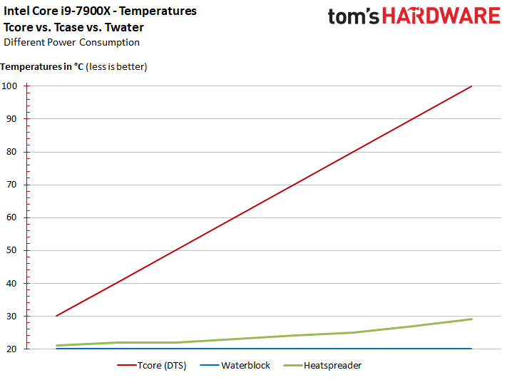
Why is this such a big deal to us? The following curve from our Core i9-7900X review, which we generated with a very high-end cooling solution, shows clearly that waste heat is dissipated poorly and inadequately with paste between the die and heat spreader. What actually worked effectively for a 91W chip like the Core i7-7700K now leads to a thermal bottleneck.
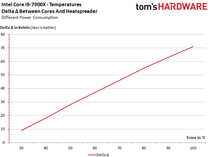
In the end, the following graph represents the glaring temperature differences between the heat spreader on top and cores underneath. We were shocked in our launch story and remain so today.
Although we're using some of the highest-end and most expensive cooling hardware available, we still measure up to a whopping 71 Kelvin difference between the cores' reported temperature and the heat spreader's top. Obviously, a more mainstream closed-loop liquid cooler under full load would look quite silly.
Observation #2: The dissipation of waste heat is hindered by the CPU's construction and Intel's deliberate decision to use thermal paste between the heat spreader and die. Regardless of how much pressure you use or how cold you can get your heat sink, you'll never realize Skylake-X's potential the way it's currently configured. Intel applies a thermal brake, favoring longevity and sacrificing performance.
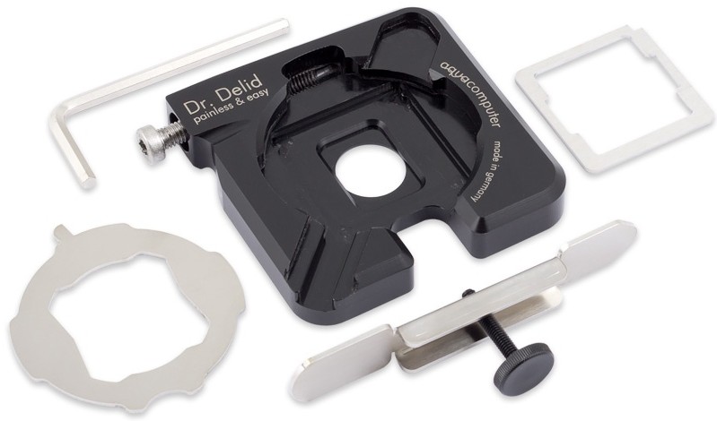
Now, you might be tempted to remove the heat spreader and replace Intel's thermal paste with something better. But that's simply not a realistic course of action for most enthusiasts. It takes a special tool, a steady hand, and some prior practice. Of course, the process also obliterates your warranty.
Get Tom's Hardware's best news and in-depth reviews, straight to your inbox.
It'd be even more extreme to leave the die exposed and use a good torque screwdriver to minimize the possibility of mechanical damage from a non-uniform/excessive load. That's still a risky move, though.
In the end, de-lidding is one solution to this cooling bottleneck, though it lacks mass appeal. A certain contingent of enthusiasts will try their hands at it regardless, and we can only caution that you consider the risks first.
Skylake-X's Integrated Voltage Regulators
Intel's Haswell and Broadwell designs employed a Fully Integrated Voltage Regulator, incorporating power delivery onto the package/die. FIVR was to simplify motherboard layouts by consolidating five platform-based voltage regulators down to just one. But the implementation created some issues for overclockers, too.
Skylake-S did away with FIVR. Now, Skylake-X re-incorporates integrated voltage regulation, though its IVR is linear, rather than switching.
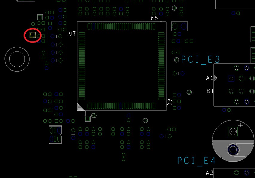
What's this all about? Well, the motherboard's external voltage converters do not deliver the Vcore, as in Kaby Lake-X, but rather an intermediate voltage (VCCIN, or eventual CPU input voltage) as input for Skylake-X's IVR. If you take a look at the picture below, you can see the point for measuring VCCIN for Skylake-X or Vcore for Kaby Lake-X. The CPU determines which voltage is delivered from the VRM, and it can be between 1.6V and up to a maximum of 2.55V.
Anecdotally, it was this hybrid approach that led to so many CPU deaths in the run-up to Intel's launch, as folks switched from Skylake-X at 1.8V to Kaby Lake-X and applied far too high of a voltage.
Based on the lower intermediate voltage VCCIN, delivered by the VRM (which does the biggest part of the voltage regulation job), the IVR generates voltage for the cores (Vcore) and all needed sub-voltages for the last-level cache, mesh topology, the I/O (VCCIO), the system agents (VCCSA), and the PIROM (VCC33).
This intermediate voltage VCCIN is controlled by the CPU via the SVID (Serial Voltage ID) bus, and the R35201 controller also supports Intel's latest VR13.0 PWM. This VID-based voltage is similar to the former loadline of the Vcc of older CPUs.
Skylake-X's Maximums & Extreme Overclocking
Intel specifies a TDP of only 140W for existing Skylake-X CPUs. The maximum current is an incredible 190A (peak, for <2ms), but also cut down to 73A for the Thermal Design Current. The Thermal Design values (for wattage and current) are defined by Intel to clarify the VRM load and cooling requirements under a constant load. The maximum package power is set to 297W. Tests with higher values cause the motherboard to shut down at 365W.
Observation #3: Power consumption for VCCIN beyond 300W has nothing to do with realistic overclocking, since the CPU is loaded beyond its thermal spec well before that point. For long-term stability, a maximum value of up to 250W is more realistic (even if it's still quite high).
MORE: Best CPUs
MORE: CPU Overclocking Guide: How (and Why) to Tweak Your Processor
MORE: Intel & AMD Processor Hierarchy
MORE: All CPUs Content
Current page: Factory Imposed Limits: Heat Spreaders, TIM & The IVR
Prev Page Skylake-X: The Current State Of Its Problems Next Page Living On The Edge (At Stock Settings)
Igor Wallossek wrote a wide variety of hardware articles for Tom's Hardware, with a strong focus on technical analysis and in-depth reviews. His contributions have spanned a broad spectrum of PC components, including GPUs, CPUs, workstations, and PC builds. His insightful articles provide readers with detailed knowledge to make informed decisions in the ever-evolving tech landscape
-
You guys don't get it??? I talked to some people who got 6 core of Skylake-X and they were able to push CPU up to 4.6Ghz on all cores where temperatures were fine under Prime. Again temperatures were much lower in anything else. In my opinion Prime is rather unrealistic stress test, not to say useless crap proving nothing. I am not defending Intel but you all approached this problem with a wrong assumption.Reply
With 7900X which is still built using 14nm fabrication process, there is no in hell you are going to be fine with temperatures on overclocked 10/20 cores. That's just too many of them to keep them cool.
If someone gets 10/20 CPU i would not push more than 4Ghz. That is a max realistic clock speed for such CPU, with 8 Core you will be better but i'd say the best thing to buy is actually 6/12 Core which can easily run at @4.5Ghz.
People don't play Prime or any other similar >Mod edit: keep it clean<test. People game, do programming, stuff where you will never see CPU showing overheating issue. And again keep 10/20 at 4.0Ghz max. Honestly you won't gain a thing running at 4.4Ghz. -
Also i might want to add is to wait for second iteration of x299 boards. The first batch is a joke from cooling point of view. Evga is one of the companies which will get it right. X299 need copper based cooling for VRM and chipset and also 2x8pin CPU connectors with recommended PSU of 1000W+. That's how i would run x299 setup.Reply
-
AgentLozen ReplyFreak777Power said:You guys don't get it??? I talked to some people who got 6 core of Skylake-X and they were able to push CPU up to 4.6Ghz on all cores where temperatures were fine under Prime. Again temperatures were much lower in anything else. In my opinion Prime is rather unrealistic stress test, not to say useless crap proving nothing. I am not defending Intel but you all approached this problem with a wrong assumption.
What's wrong with using Prime? It does a good job of testing the thermal limits of a CPU. You wouldn't test the limits of a weight lifters strength with 5 pound dumb bells. You need to go all out.
You say that the author of this article approached this problem with a wrong assumption. Do you think that there's nothing noteworthy of Skylake X's thermal performance?
I think this article did a good job of pointing out the glaring flaws of Skylake X. The conclusion is really interesting: "We're getting the sense, though, that the revered Core architecture can't be pushed much further." That gives me chills. I never thought I'd see the day when Core hit its limits. -
rothbardian Reply19921133 said:The conclusion is really interesting: "We're getting the sense, though, that the revered Core architecture can't be pushed much further." That gives me chills. I never thought I'd see the day when Core hit its limits.
It's a chilling conclusion indeed. It all points out to AMD's multi-die, multi-ccx architecture of Ryzen Threadripper being supperior to Inte's Core on all counts. -
Wisecracker Good job -- Thank you for the in-depth analysis.Reply
BUT (you knew that was coming ;) right?), I question the need to call-out motherboard OEMs. I agree with the comments regarding unnecessary 'Bling' but they clearly feel they are delivering what the market demands in that regard ...
It seems off-kilter to focus/blame board components and OEMs at the top of your conclusion page, and not really Chipzilla, while noting Sky(lake-X)-rocketing heat/power beyond that of the previous-gen 32nm AMD FX-9590 (constantly derided since its introduction as a power-hungry 'heater').
Know what I mean, Vern?
edit: How could I have misquoted Earnest!
-
FormatC To be honest, this was translated in absolute hurry over the weekend and sounds now (without my lyrics) a bit harsh. But one thing is fact: without all this kiddish plastic crap, covering the cooler surface, it might work a lot better. As I wrote on page One (intro); it is a causal chain and at the begin is the CPU.Reply -
AgentLozen ReplyWisecracker said:See what I mean, Vern?
I know its petty, but isn't the line, "Know what I mean?" We're talking Jim Varney, right? Haha. -
JamesSneed This article spells out the points why I decided to build a Ryzen based system. I waited for Skylake-x and the thermals / power are just way to off the charts for the little extra performance. I could not be happier with the Ryzen 1800x build and yes I know I paid more for something you can get in the 1700 and OC it. I certainly agree anyone needing more than 8-cores should wait on Threadripper as it really has a chance to take Intel on performance due to these very same thermal / power issues in the i9 which means the higher core counts won't hit the same frequencies.Reply -
JamesSneed Reply19921311 said:To be honest, this was translated in absolute hurry over the weekend and sounds now (without my lyrics) a bit harsh. But one thing is fact: without all this kiddish plastic crap, covering the cooler surface, it might work a lot better. As I wrote on page One (intro); it is a causal chain and at the begin is the CPU.
I agree, they should be called out when form causes a hit to function. I didn't find it harsh at all. Motherboard makers are all enamored right now with shiny pretty and are loosing sight on quality. I don't care if it has LED's or looks "cool" but never should that be at the expense of the motherboards main function. -
mrjhh Power consumption and TDP are only marginally linked. Maximum power consumption relates to the maximum the chip could possibly use, while TDP is what a heat sink needs to be able to dissipate. The chip will thermally throttle if the maximum power consumption extends for long, but this condition should not happen in normal usage. But, if one uses all execution units within the processor at the same time, one will hit maximum power consumption at least momentarily. But, it's hard to keep all execution units running all the time, as there are typically cache misses which slow the processor, as well as software inefficiencies preventing running all execution units all of the time. Normally, that would put the average power consumption within TDP limits. Unusual use cases could exceed TDP, and cause thermal throttling.Reply
