The Skylake-X Mess Explored: Thermal Paste And Runaway Power
Skylake-X: The Current State Of Its Problems
In the wake of Skylake-X's introduction and disappointing results from our overclocking attempts, we put a lot of thought into the power and thermal issues plaguing Intel's highest-end desktop CPUs. These roadblocks boil down to a couple of salient points that we'd like to explore in as much depth as possible:
(1) Skylake-X at its stock settings can barely be cooled during normal operation. This is due to its power consumption being extremely high in some situations, and its thermal paste keeping waste heat from being dissipated effectively.(2) There’s barely any room for enthusiasts to overclock. Also, many motherboards limit Skylake-X CPUs further due to poor design choices, such as insufficient VRM cooling. Those looking for high overclocks need not apply.
Test Equipment & Setup
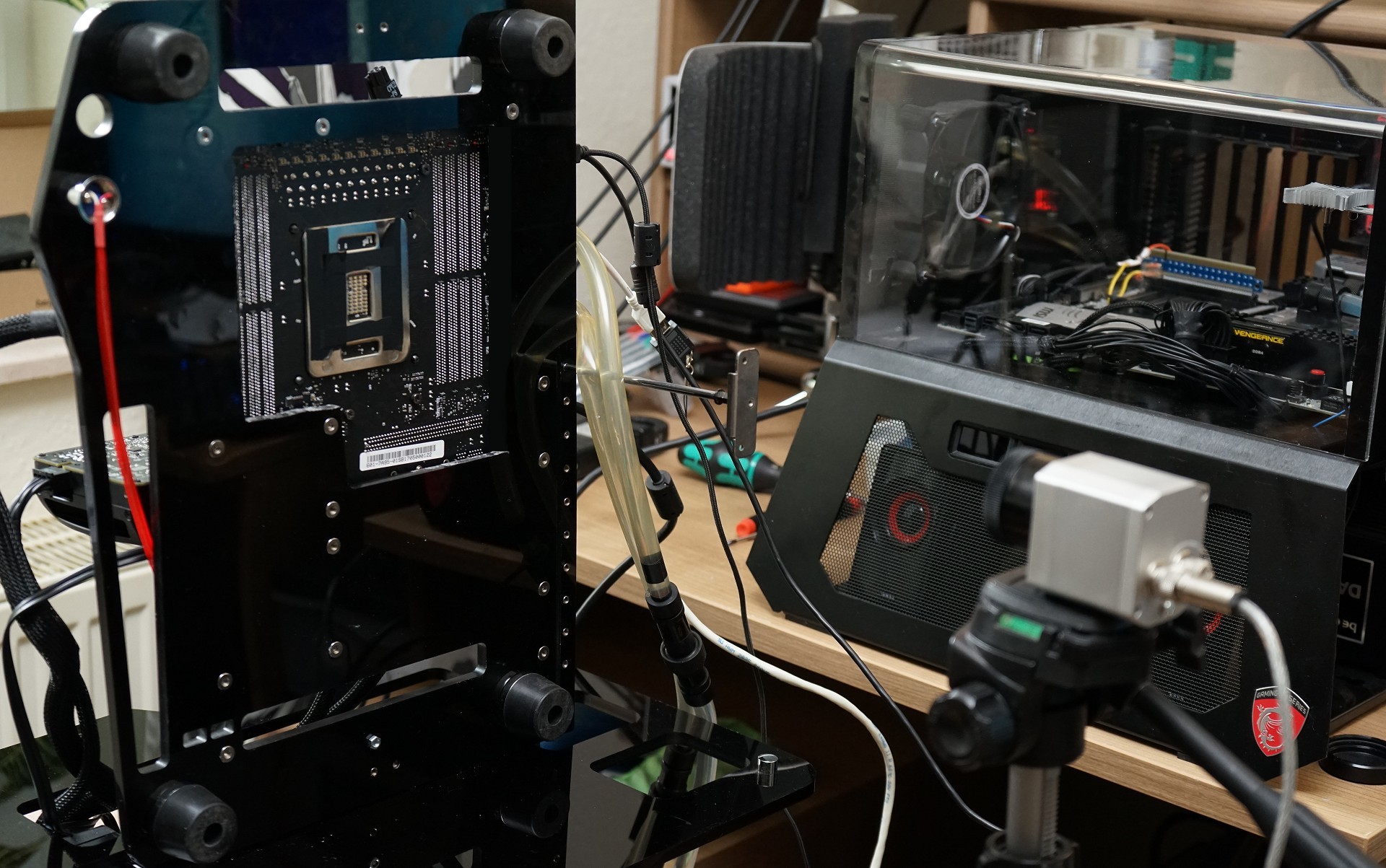
In an effort to suss out both points, we decided to grab one of the simpler LGA 2066 motherboards out there, build a bench table capable of supporting vertical operation, and start running Core i9-7900X through more tests.
Our experiments went two directions. First, we examined thermal sensor readings and where they were reporting heat. Second, we compared our infrared thermal measurements around the motherboard's LGA interface and VRMs to double-check the sensors' plausibility. This also allowed us to document the warm-up phase and how heat spread via time-lapse videos.
Finally, we’re interested to know if and how other on-board components are affected by the processor-imposed hot-spots.
We’re using the most current version of our motherboard’s BIOS to guarantee reliable sensor readings, along with stable operation. The new beta version of HWiNFO (v5.53-3190) was chosen for the same reasons.
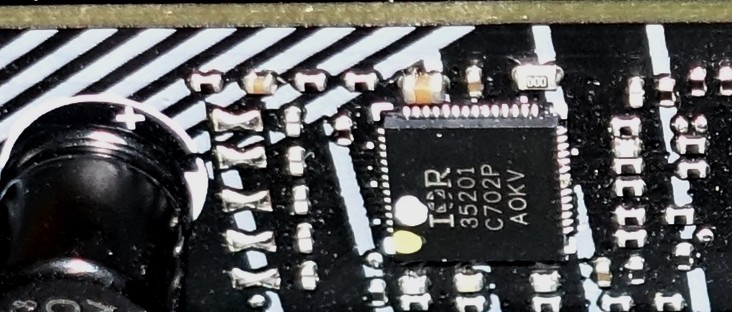
The motherboard's CPU power supply employs a total of 5+1 phases, realized by an International Rectifier IR35201 dual-loop buck controller. It officially supports Intel’s VR12.5 Rev 1.5, and also apparently VR13. Kudos if you counted more regulator circuits; doubling of five phases allows two circuits per phase, reducing each VRM's load and spreading hot-spots out more evenly.
Get Tom's Hardware's best news and in-depth reviews, straight to your inbox.
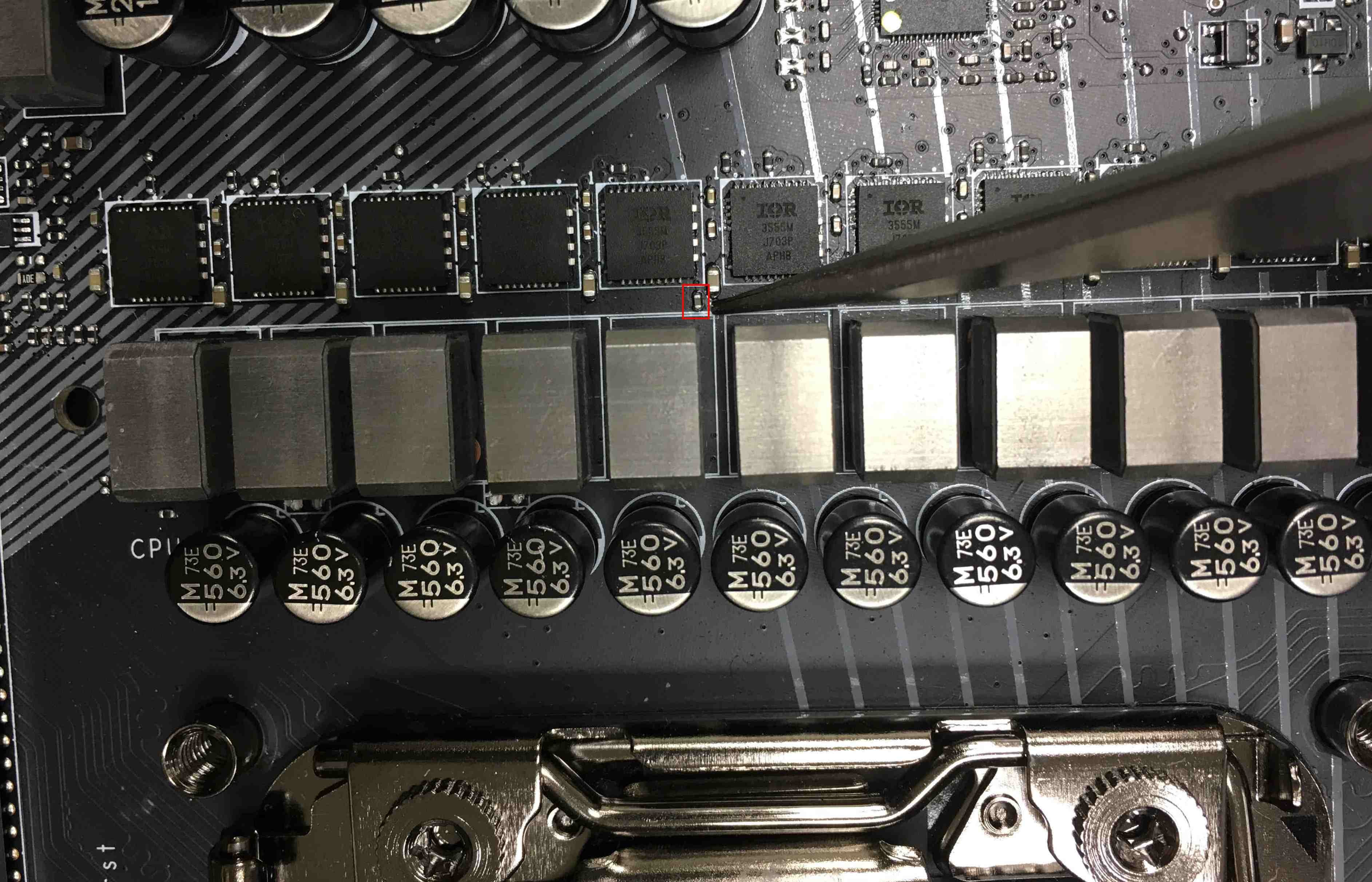
Each circuit has its own 60A IR3555 PowIRstage. These highly integrated chips combine the necessary gate drivers, high- and low-side MOSFETs, and Schottky diode in one package. In contrast with most MOSFETs, the IR3555 is able to read analog values for the built-in temperature sensor. So, how is it possible to also determine the temperature of hot-spots on the PCB without an IR camera handy?
MSI uses Nuvoton's NCT6795D Super I/O chip, which is able to collect and report a wide variety of sensor readings. One of these readings comes from a thermistor (see picture below) placed among the PowIRstage chips. This is why we chose the spot right underneath this thermistor, on the motherboard's back side, as the location for our video-based measurements.
Additionally, we'll check temperatures on the regulator circuits’ chokes and capacitors, as well as board temperatures all the way to the CPU.
Frequency Throttling & Emergency Shutdown
It’s important to understand that motherboard manufacturers deliberately add certain safety mechanisms to their designs. One example from our test platform is that a Skylake-X processor’s clock rate throttles to exactly 1.2 GHz if the thermistor reports a temperature of 105°C or more (see the MOS line in the image below). That frequency is maintained until the temperature drops under 90°C. Only then does it restore the processor’s full speed.
Even though the board material’s flashpoint (FR4) is significantly higher than 105°C, the recommended maximum temperatures for continued operation is between 95 and 105°C. Otherwise, the motherboard might suffer from dry-out, bending, or hairline fractures in the conductor paths. This safety-consciousness is a welcome trend, to be sure.
Enthusiasts using Intel’s Extreme Tuning Utility (XTU) can find this setting under Thermal Throttling: Yes, in yellow. But what about other settings, such as Motherboard VR Throttling?
First, a bit of background. Without the corresponding MOSFETs with temperature sensor output (mostly as voltage) the IR35201 buck controller provides its own temperature readings. Long ago, it was supposedly possible to read voltage converter temperatures as VRM1 and VRM2 for graphics cards with certain PWM controllers. However, the temperature values weren’t determined by temperature sensors, but by the chip measuring itself, because the MOSFETs being used didn't have sensors inside.
In our case, we get the reported values from within the PowIRstage. After all, the values under VR T1 and VR T2 are significantly higher than we'd expect.
The PWM controller can only guarantee a stable and safe power supply if all components stays within its technical specifications. This means that a maximum temperature setting is necessary. Here, that's 125°C. At and above 125°C, XTU’s Motherboard VR Throttling: Yes setting turns yellow and the CPU’s frequency throttles to 1.2 GHz. At 135°C, the motherboard simply shuts down to avoid hardware damage.
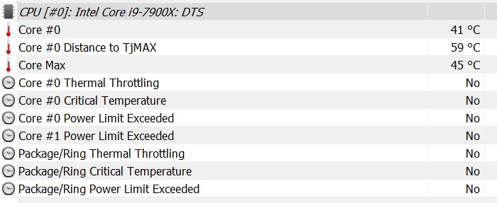
The CPU protects itself as well. It estimates the temperatures for its cores and package based on readings from different integrated digital temperature sensors (DTS). The precision of those estimates increases as the sensors get hotter. Under 40°C, their measurements are meaningless. However, they're very accurate above 80°C, which is where it counts. If the core or package temperature gets too hot, throttling ensues.
The package temperature includes the integrated voltage regulator’s leakage currents. The IVR is responsible for providing different voltages to subsystems within the CPU. High overclocks and manual voltage increases can cause the temperature limit to be exceeded unexpectedly. Tools might not be able to reliably capture this effect, which means that the CPU might throttle without any reason that would be visible to the user.
Observation #1: It’s well-known that the CPU might throttle its clock rate due to its core or package temperatures being too high. However, the Super I/O chip might also throttle it due to VRM temperatures being too high. Finally, the PWM controller can also cause throttling if it gets too hot, since this could result in a dangerously unstable power supply. Moreover, it’s an urban legend that the PWM controller can report VRM temperatures.
The Test System
| Test Equipment and Environment | |
|---|---|
| System | Intel Core i9-7900XMSI X299 Gaming Pro Carbon AC4x 4GB G.Skill Ripjaws IV DDR4-2600Nvidia Quadro P6000 (Workstation)1x 1TB Toshiba OCZ RD400 (M.2, System)2x 960GB Toshiba OCZ TR150 (Storage, Images)Be Quiet Dark Power Pro 11, 850W Power Supply Unit (PSU)Windows 10 Pro (Creators Update) |
| Cooling | Alphacool Eiszeit 2000 Chiller + Alphacool Eisblock XPXAlphacool Eisbär 240 (All-in-one Water Cooler)Noctua NH-D15 (Air Cooler)Thermal Grizzly Kryonaut (Used when Switching Coolers) |
| Monitor | Eizo EV3237-BK |
| Power Consumption Measurement | Direct Current Measurement at Shunts (Voltage Drop)Direct Current Measurement at Measurement PointsContact-free DC Measurement at External Auxiliary Power Supply Cable2x Rohde & Schwarz HMO 3054, 500MHz Digital Multi-Channel Oscilloscope with Storage Function 4x Rohde & Schwarz HZO50 Current Probe (1mA - 30A, 100kHz, DC) 4x Rohde & Schwarz HZ355 (10:1 Probes, 500MHz) 1x Rohde & Schwarz HMC 8012 Digital Multimeter with Storage Function |
| Thermal Measurement | 1x Optris PI640 80Hz Infrared Camera + PI Connect Real-Time Infrared Monitoring and RecordingPictures and Emission Videos |
MORE: Best CPUs
MORE: CPU Overclocking Guide: How (and Why) to Tweak Your Processor
MORE: Intel & AMD Processor Hierarchy
MORE: All CPUs Content
Current page: Skylake-X: The Current State Of Its Problems
Next Page Factory Imposed Limits: Heat Spreaders, TIM & The IVR
Igor Wallossek wrote a wide variety of hardware articles for Tom's Hardware, with a strong focus on technical analysis and in-depth reviews. His contributions have spanned a broad spectrum of PC components, including GPUs, CPUs, workstations, and PC builds. His insightful articles provide readers with detailed knowledge to make informed decisions in the ever-evolving tech landscape
-
You guys don't get it??? I talked to some people who got 6 core of Skylake-X and they were able to push CPU up to 4.6Ghz on all cores where temperatures were fine under Prime. Again temperatures were much lower in anything else. In my opinion Prime is rather unrealistic stress test, not to say useless crap proving nothing. I am not defending Intel but you all approached this problem with a wrong assumption.Reply
With 7900X which is still built using 14nm fabrication process, there is no in hell you are going to be fine with temperatures on overclocked 10/20 cores. That's just too many of them to keep them cool.
If someone gets 10/20 CPU i would not push more than 4Ghz. That is a max realistic clock speed for such CPU, with 8 Core you will be better but i'd say the best thing to buy is actually 6/12 Core which can easily run at @4.5Ghz.
People don't play Prime or any other similar >Mod edit: keep it clean<test. People game, do programming, stuff where you will never see CPU showing overheating issue. And again keep 10/20 at 4.0Ghz max. Honestly you won't gain a thing running at 4.4Ghz. -
Also i might want to add is to wait for second iteration of x299 boards. The first batch is a joke from cooling point of view. Evga is one of the companies which will get it right. X299 need copper based cooling for VRM and chipset and also 2x8pin CPU connectors with recommended PSU of 1000W+. That's how i would run x299 setup.Reply
-
AgentLozen ReplyFreak777Power said:You guys don't get it??? I talked to some people who got 6 core of Skylake-X and they were able to push CPU up to 4.6Ghz on all cores where temperatures were fine under Prime. Again temperatures were much lower in anything else. In my opinion Prime is rather unrealistic stress test, not to say useless crap proving nothing. I am not defending Intel but you all approached this problem with a wrong assumption.
What's wrong with using Prime? It does a good job of testing the thermal limits of a CPU. You wouldn't test the limits of a weight lifters strength with 5 pound dumb bells. You need to go all out.
You say that the author of this article approached this problem with a wrong assumption. Do you think that there's nothing noteworthy of Skylake X's thermal performance?
I think this article did a good job of pointing out the glaring flaws of Skylake X. The conclusion is really interesting: "We're getting the sense, though, that the revered Core architecture can't be pushed much further." That gives me chills. I never thought I'd see the day when Core hit its limits. -
rothbardian Reply19921133 said:The conclusion is really interesting: "We're getting the sense, though, that the revered Core architecture can't be pushed much further." That gives me chills. I never thought I'd see the day when Core hit its limits.
It's a chilling conclusion indeed. It all points out to AMD's multi-die, multi-ccx architecture of Ryzen Threadripper being supperior to Inte's Core on all counts. -
Wisecracker Good job -- Thank you for the in-depth analysis.Reply
BUT (you knew that was coming ;) right?), I question the need to call-out motherboard OEMs. I agree with the comments regarding unnecessary 'Bling' but they clearly feel they are delivering what the market demands in that regard ...
It seems off-kilter to focus/blame board components and OEMs at the top of your conclusion page, and not really Chipzilla, while noting Sky(lake-X)-rocketing heat/power beyond that of the previous-gen 32nm AMD FX-9590 (constantly derided since its introduction as a power-hungry 'heater').
Know what I mean, Vern?
edit: How could I have misquoted Earnest!
-
FormatC To be honest, this was translated in absolute hurry over the weekend and sounds now (without my lyrics) a bit harsh. But one thing is fact: without all this kiddish plastic crap, covering the cooler surface, it might work a lot better. As I wrote on page One (intro); it is a causal chain and at the begin is the CPU.Reply -
AgentLozen ReplyWisecracker said:See what I mean, Vern?
I know its petty, but isn't the line, "Know what I mean?" We're talking Jim Varney, right? Haha. -
JamesSneed This article spells out the points why I decided to build a Ryzen based system. I waited for Skylake-x and the thermals / power are just way to off the charts for the little extra performance. I could not be happier with the Ryzen 1800x build and yes I know I paid more for something you can get in the 1700 and OC it. I certainly agree anyone needing more than 8-cores should wait on Threadripper as it really has a chance to take Intel on performance due to these very same thermal / power issues in the i9 which means the higher core counts won't hit the same frequencies.Reply -
JamesSneed Reply19921311 said:To be honest, this was translated in absolute hurry over the weekend and sounds now (without my lyrics) a bit harsh. But one thing is fact: without all this kiddish plastic crap, covering the cooler surface, it might work a lot better. As I wrote on page One (intro); it is a causal chain and at the begin is the CPU.
I agree, they should be called out when form causes a hit to function. I didn't find it harsh at all. Motherboard makers are all enamored right now with shiny pretty and are loosing sight on quality. I don't care if it has LED's or looks "cool" but never should that be at the expense of the motherboards main function. -
mrjhh Power consumption and TDP are only marginally linked. Maximum power consumption relates to the maximum the chip could possibly use, while TDP is what a heat sink needs to be able to dissipate. The chip will thermally throttle if the maximum power consumption extends for long, but this condition should not happen in normal usage. But, if one uses all execution units within the processor at the same time, one will hit maximum power consumption at least momentarily. But, it's hard to keep all execution units running all the time, as there are typically cache misses which slow the processor, as well as software inefficiencies preventing running all execution units all of the time. Normally, that would put the average power consumption within TDP limits. Unusual use cases could exceed TDP, and cause thermal throttling.Reply
