APC BX1000 Click-of-Death Repair
From Input To Output
When going through power supply rails fails to reveal a smoking gun, it is time to look at what happens between inputs and outputs. In the case of a UPS, this is rather simple since it only possesses one critical input and output: the power cord and outlets. What the UPS repeatedly engaging the AVR transformer tells us is that something must not be working correctly in the line voltage detection circuit.
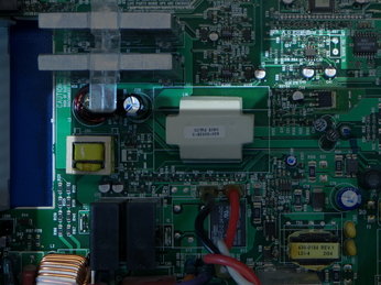
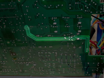
AC inputs (live and neutral in the bottom-left corner on the top side) pass through two resistor ladders as a differential voltage divider, jump to the bottom layer to the left of the current-sensing transformer, and travel two-thirds of the way across the board before popping back on the top layer to reach the inputs of an LM358 op-amp (pins two and three) in the upper-right corner of the top-side picture. I suspect that the LM358 is set up as a simple differential amplifier, and unless there is some special trick to the circuit beyond the inputs, we should expect its output on pin one to be a low-amplitude representation of the input line voltage.
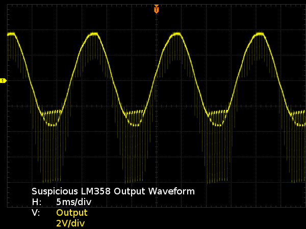
Do I need to tell you that this looks suspicious? The positive halves are clean apart from narrow downward spikes, while the negative halves are all chopped up with spikes to -8V and parts of the waveform are clipped at about -2.4V. Where does this chopping come from? More important, if the LM358 is outputting negative voltage, it must be receiving a negative supply from somewhere, and I need to measure it on pin four. I might as well check the positive supply on pin eight while I’m at it. I should have thought of that previously when I noticed the presence of an LM358 and LM359, since op-amps and comparators often require negative voltage.
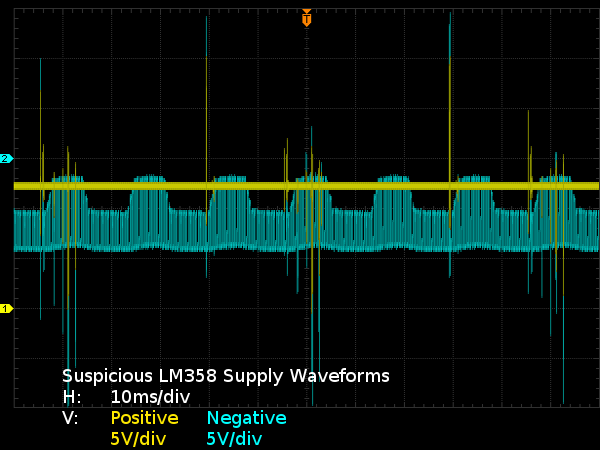
What we have here, aside from large spikes attributable to common-mode noise, which you should ignore, is a supply rail that collapses immediately after receiving a charge pulse and has an envelope that somewhat resembles a 60Hz half-sinusoid. The negative voltage rail’s pulses are being clipped by the op-amp attempting to drive its output negative. That’s the calling card of a dead storage capacitor on the op-amp’s negative supply. Could all of the BX1000’s issues be caused by a single failed 22µF 16V capacitor on a minor negative rail? Time to blow C41 off from the board and put a 10µF MLCC capacitor in its place.
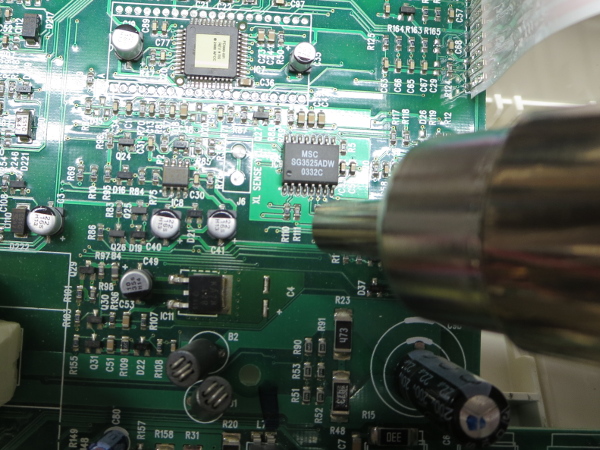
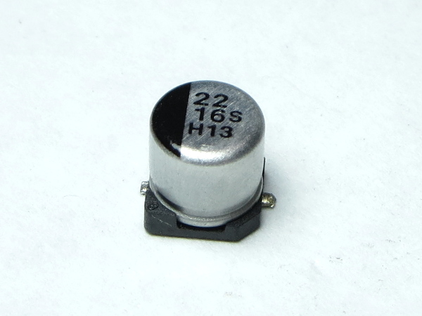
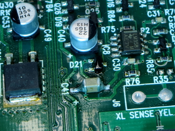
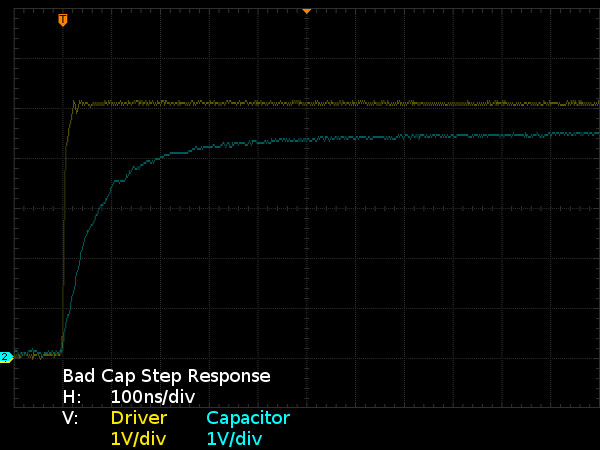
Since surface-mount electrolytics are propped on tiny plastic coasters with their flat leads folded sideways underneath, the easiest way to get them on and off of boards is using hot air. Once the old capacitor blown away, I added a small amount of solder to its pads and applied hot air to put the new ceramic capacitor in its place. I tried measuring the old capacitor’s value using my multimeters and got inconsistent readings between attempts, which tells me the little bugger is thoroughly hosed. It's time to break out my old step response capacitor test rig and see how bad it is.
The RC curve rises to 99% of its steady-state value in about 600ns with 500Ω of drive resistance, which means that the capacitor’s effective capacitance is in the order of one nanofarad, or 1/20,000th of its nominal value. It's only marginally better than having nothing there at all. The way the charge curve settles 500mV below the drive curve also tells us that the capacitor is leaking approximately 1mA at 4.5V, which is over three orders of magnitude worse than typical for such small capacitors. Having 1mA of leakage may not sound like a big deal, but for a charge-pump converter only meant to power the negative rail of some very low-power devices, it's enough to ruin your day. What does the op-amp’s supply rails look like with the new bypass capacitor?
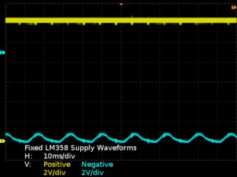
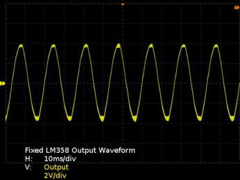
Much better. There is still enough ripple on the negative rail to make people cringe when comparing it to the ATX spec. While it could easily be halved if I had a 22µF capacitor to put in there, at least the high-frequency noise from whatever generates the supply rail is effectively gone and the rail remains below -8V. That should be enough margin to accommodate the LM358’s ±4V output range and let the op-amp supply noise rejection ratio take care of the rest. This simple fix is worlds better than the choppy nonsense we saw before. How about the LM358’s output? The negative crests look slightly fuzzier than the positive ones, but we otherwise have what looks like a reasonable representation of the AC input waveform we were originally expecting.
Get Tom's Hardware's best news and in-depth reviews, straight to your inbox.
Sure enough, the UPS turns on without hesitation or clicking, stays on through its built-in self-test routine, then transitions to its normal operating mode without randomly going into AVR boost/buck or battery mode. Cut the power and the UPS kicks in, turn power back on and it switches back to AC power after a few seconds.
Why did the UPS fail to power up? While I haven’t positively identified the mechanism causing it to fail, I’ll hazard a guess that its 5V micro-controller’s ADC did not like having -8V spikes at its input.
That’s one mystery solved. Now on to the next one: why did the capacitor fail in the first place?
MORE: APC BR1000G Tear-Down
MORE: APC BN650M1-CA Tear-Down
MORE: APC BGE90M-CA Tear-Down
Current page: From Input To Output
Prev Page Following My Own Advice Next Page What Is A Charge Pump?-
Zaxx420 'Now on to the next one: why did the capacitor fail in the first place?'Reply
That's one aspect that sooo many folks never consider or can't be bothered to investigate. Just like a fuse that keeps blowing...there is something that's causing it to blow...even if it lasts a while before blowing. Even worse is when they decide to bridge it with a piece of wire or wrap the blown (glass) fuse with aluminum foil. Now I'm guilty as well but ONLY long enuff to get myself out of a jam...like being stranded on the side of the road or something. Just never do it with a high current load or if it's blowing the instant you turn it on...and never with a sensitive/expensive critical component like the ignition ECU of your self semi-restored muscle car project...don't ask. -
Daniel Sauvageau Reply
The repair is already done and I'm not set up for recording - don't even own a video camera or webcam. Even if I did own one, I'm no good with talking and working at the same time. Also, if I posted repairs on YouTube, I wouldn't be able to post them on THG since THG is paying me for exclusive publication.18828366 said:When you do fix it, can you YouTube it?
Too much credit :) This is basic troubleshooting, anyone going through electronics tech training should be able to do as before graduation.18830162 said:You are so smart.
-
jcamilo70 I have a 2005 RS1200 that died on me, making clicking sound constantly, and only turning on directly into battery mode.Reply
Where did you manage to get the replacement pieces? Where could I find the micro-controller for this unit or how should I identify its part number in order to look for it? -
Daniel Sauvageau Reply
The only part I needed to replace here was that single capacitor. Where did I get the capacitor from? It was just one of many leftover parts I've accumulated either from ordering more parts than necessary for past repairs/projects, or parts I had ordered for potential future projects to pad orders for free S&H. I may have over $2000 worth of parts in my spare parts and samples boxes.18830308 said:I have a 2005 RS1200 that died on me, making clicking sound constantly, and only turning on directly into battery mode.
Where did you manage to get the replacement pieces? Where could I find the micro-controller for this unit or how should I identify its part number in order to look for it?
For the micro-controller, I didn't touch it. Even if I had wanted to replace it, they can only be ordered blank from parts distributors (or pre-programmed with your own firmware for large enough orders or distributors that offer such a service for an additional fee) and those would be no good without the correct firmware to put on them. If the controller died, it is game over unless you can find a donor UPS based on the same PCB. -
powernod This example showed us the importance of high quality caps to be used in such critical components such as a UPS/PSU. A single cap-failure (*from the many a UPS uses) and caused total malfunction of the UPS !!Reply
P.S. This review has also shown us the importance/need for UPSs reviews. Since PSUs are being thoroughly reviewed for many years, i don't understand why UPSs shouldn't be reviewed as well!! A PSU's proper operation is in consequence with the proper operation of the hardware that "feeds" a PSU (*UPS)
P.S.2 : Great article by the way!!
