Hacking Your Mouse To Fix The Misclick Of Doom
Ever had your patience put on trial by glitchy mouse buttons? That is one problem that simply should never have been on any half-decent mice.
Debouncing SPDT Switches
Single-pole, double-throw switches enables many debouncing options when using all three terminals, and it is a shame that companies like Logitech that use SPDT switches in most of their mice do not take full advantage of them. In every Logitech mouse I have opened, only the common and NO contacts are used; the NC pin is only present for mechanical support. The simplest analog debounce method is to tie the NO contact to VCC, the NC contact to ground and connect a resistor-capacitor (RC) filter on the common (blade) contact for the output. This way, the capacitor holds its voltage whenever the blade is in-flight between contacts.
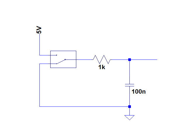
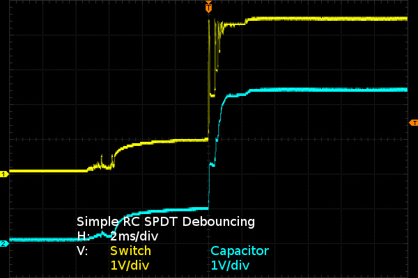
This awfully simple implementation already eliminates most of the bounce noise that would be seen by the controller's input. If I didn't tell you that the waveform was created using the crusty old switch, it could be easily be mistaken for a new one (unless you looked at the flight time, which is still around eight milliseconds between the beginning of the hump indicating initial break with the NC/ground contact and the first peak indicating contact with NO/VCC). Here, the hump is due to leakage current through the mouse because I hooked up the switch in-circuit instead of desoldering it. That's not ideal, since feeding power through the controller's inputs and outputs might fry them. But if I do fry something, I still have a spare. With a 1kΩ resistor in-circuit, though, damage is unlikely since five milliamperes is well within the tolerances of ESD protection diodes on input pins and CMOS transistors' body diodes on output pins. If the controller uses transistor-to-transistor logic (TTL), then less than 5V current-limited to less than 5mA is not going to hurt anything either.
Is it possible to do better than this? Of course. Instead of relying on a capacitor to hold the value, you can use a Schmitt trigger buffer or equivalent, which can easily be integrated into a chip to eliminate external components.
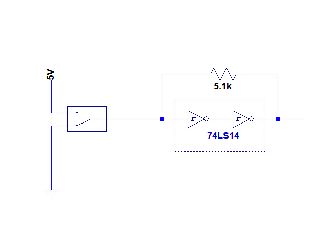
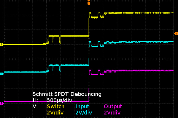
I used the 74LS14 (hex Schmitt-trigger input inverter) as my Schmitt buffer since that was the first chip I found in my parts box with Schmitt inputs. Given that it is an inverter, I put two in cascade to simulate a non-inverting Schmitt trigger. Internally, a Schmitt behaves like a comparator with positive internal feedback to create hysteresis, reducing susceptibility to noise. Once the input passes the high threshold, typically 1.6V in this case, the output goes high and won't go low again until the input drops below 0.7V. The feedback resistor in my circuit keeps the input from going floating while the blade (common) is bouncing or in-transit between contacts, since leaving the pin floating would let it pick up random noise or let it get pulled up/down by leakage currents.
The way this works is simple: as soon as the switch touches the NO contact, the Schmitt trigger goes high and holds its own input there until the switch is done bouncing. The same process repeats on the NC side when the switch is released.
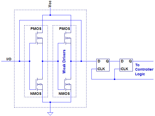
How simple would it be to implement inside an integrated circuit? In this specific application, we aren't even interested in the full Schmitt trigger functionality, only the decisive switching characteristic and the value-hold from the feedback resistor. Reduced to CMOS transistors, two inverters back to back with a feedback resistor translates to the following:
What is this? Nothing more than an elemental static memory cell. If the input drive is stronger than the second inverter's weak drivers, such as a switch making contact with the NO or NC contact connected to VCC or ground, and it brings the first inverter's gate voltage over its threshold, the cell switches state to match the input. Otherwise, it holds its current state. As far as semiconductors go, it does not get much cheaper and simpler.
Get Tom's Hardware's best news and in-depth reviews, straight to your inbox.
The two D-type flip-flops (DFFs) to the right are a standard interface between two different clock domains (asynchronous input versus clocked logic in this case) to eliminate glitches that might occur when the input changes within the D-flop's setup-and-hold window around clock edges: when a timing or input signal level violation occurs, the DFF may oscillate for hundreds of picoseconds. Putting two DFFs in cascade lets the first one oscillate and settle before the second one clocks in that stable state for the rest of internal logic to use.
Is it possible to do even better? Sure. The two previous options only required one controller pin each. If you can afford two pins per switch input, then you can use set-reset (SR) latch debouncing.
What does an SR latch do? The simplest tool to help explain it is the good old truth table.
| SR Latch Truth Table | ||
|---|---|---|
| S | R | Q |
| 0 | 0 | Q' (hold) |
| 1 | 0 | 1 |
| 0 | 1 | 0 |
| 1 | 1 | undefined |
When both S and R are low, the latch holds whatever its previous output (Q') was. When S (set) goes high, Q goes high, when R (reset) goes high, Q goes low. If both S and R are high at the same time, behavior is technically undefined but many implementations have a dominant input to avoid oscillation or other unstable states. How do you use that for debouncing an SPDT switch? It is very simple.
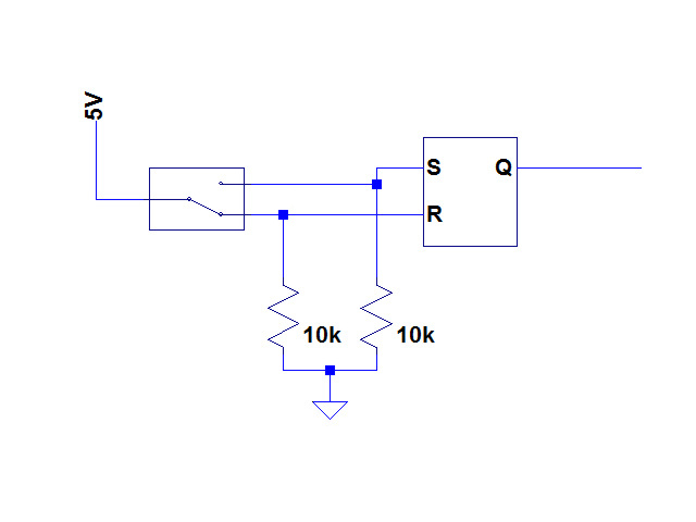
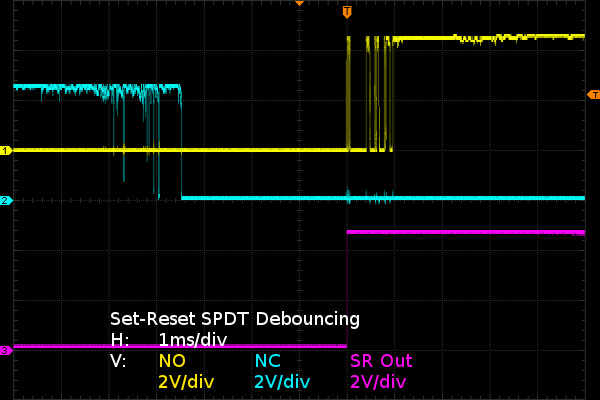
When the blade touches the NC contact, the SR latch gets reset, when it touches the NO contact, the latch gets set. When the blade is in-flight for whatever reason, the pull-down resistors keep both inputs low and the SR latch holds whatever value it previously had. In an integrated circuit, the resistors would get replaced by more space-efficient FET current sinks.
Short of a mechanical failure, it is physically impossible for the blade to simultaneously touch both the NO and NC contacts, which means no need to worry about the undefined behavior case when both inputs are high. Since an SR latch manufactured on a sub-micron process has nanosecond-scale reaction time or faster, while switches bounce at least three orders of magnitude slower in the microseconds time scale, glitching an SR debouncer through mechanical means is nearly impossible. Moreover, the first bounce should be the hardest with all the moving components' inertia and spring force behind it, guaranteeing firm initial contact to set or reset the latch. Once the latch has been set or reset by that first bounce, any other bounces on that side cannot glitch the SR latch since that input becomes a “don't care” (no effect) until the other one goes high, which is physically guaranteed not to happen within hundreds of microseconds by travel time. With soft, worn switches, that might turn into milliseconds.
In my implementation, I used a CD4043. We can see that SR debouncing produces glitch-free output on the first bounce. If mouse manufacturers used SR debouncing with their SPDT switches, the glitchy button problem would be history. The single-pin Schmitt/SRAM debounce would achieve this goal too without the expense of an extra pin per switch; all it needs is the SPDT switches wired to both VCC and ground. This is one more example of perfectly good theory not getting used in practice to save pennies per unit and also to perpetuate planned obsolescence. That is, sales would drop if you no longer needed a new mouse every two to four years as a result of glitchy buttons.
In all three SPDT debouncing cases, there is also the slight disadvantage that switch release cannot be detected until the blade has returned in the NC position, which may translate into a few milliseconds of extra input latency on button release for the blade's return trip. Is that a big deal? Unlikely, since the press/make input latency is typically far more important than the release, and travel time in both directions is roughly the same. I would not mind trading four milliseconds of release latency for never having to worry about button presses randomly releasing ever again.
That's one common type of switch taken care of; there's one more to go.
Current page: Debouncing SPDT Switches
Prev Page The Best Case Scenario And The Aged Scenario Next Page Debouncing SPST Switches-
SirGCal My problem with my MS is just finding a mouse I can use well period.I have some mice like this trackball myself and still can't use it properly. I need one controlled with the mind instead of hand. Which is probably coming sooner then we think.Reply -
theaudiophile Holy shit, you're crazy in many many ways. I am an electronics hobbyist myself, and you sir are simply insane. I hope this article gets enough traffic and ad clicks to make up for the time you put in instead of replacing switches.Reply -
mikesinner Both me and a friend of mine have already bought new mice, but I did keep the old one, a logitech G700 with the terribly annoying double click glitch when only single clicking. It's not a very old mouse either, so I find it very disturbing that the switch is already worn!Reply -
Daniel Sauvageau Reply
You give me too much credit. This is a simple hack once you know what you are dealing with - finding out what you have to work with is usually the most tedious part of a modification job, especially when you don't have design schematics or someone else's instructions to start from.17690562 said:Holy shit, you're crazy in many many ways. I am an electronics hobbyist myself, and you sir are simply insane.
The hack might be more trouble than it is worth but it does show that there is no reason for mouse buttons with SPDT switches to glitch until the switch mechanically fails. Other than mice manufacturers choosing to design them this that way that is.
My G500S is about four years old and the glitching is at that early stage where I'm not sure if the glitches are caused by the mouse or by mouse movement when I click.17690678 said:Both me and a friend of mine have already bought new mice, but I did keep the old one, a logitech G700 with the terribly annoying double click glitch when only single clicking. It's not a very old mouse either, so I find it very disturbing that the switch is already worn!
-
BulkZerker http://www.epicpants.com/t-shirts/tek-syndicate-gaming-mouse-standard-issueReply
Problem solved.
-
razor512 Wouldn't it be easier to just use hall effect switches (like with some industrial machines)?Reply
The switches can be magnetically shielded, and as long as the button actuation functions (no broken springs), the button will continue to work, along with any vibrations of the actuation being calibrated out in software. -
buzzrattie Wish there were a mouse that was cat-hair proof. Dang little buggers shedding all the time, and getting into the laser.Reply -
Daniel Sauvageau Reply
I doubt switches that require additional calibration steps would be popular in a market where manufacturers are trying to optimize every penny of profit they think they can get away with out of their product.17691040 said:Wouldn't it be easier to just use hall effect switches (like with some industrial machines)?
The switches can be magnetically shielded, and as long as the button actuation functions (no broken springs), the button will continue to work, along with any vibrations of the actuation being calibrated out in software.
One option which does not require calibration is optical sensing: poke a slotted stem through the detector. Most mechanical mice used optical wheel encoders to convert ball motion to digital. The same thing could be done for switches.
I doubt either option would be as inexpensive as a mechanical switch and with the "memory" version of my hack, it would be a practically free fix. Free is a tough price to beat.
