Hacking Your Mouse To Fix The Misclick Of Doom
Ever had your patience put on trial by glitchy mouse buttons? That is one problem that simply should never have been on any half-decent mice.
From The Mouse's Mouth
Before I can consider modding a mouse to implement any of the possible debouncing enhancements we've already discussed, I need to know what I am working with. The previously explored debouncing circuits assumed that the switch connects to either power or ground. But my past efforts at debouncing switches by simply sticking capacitors across their contacts' pins proved ineffective, indicating that something less obvious must have been happening. That was before I owned an oscilloscope, though. Now I can revisit my TrackMan Marble to see if I can design an elegant and reliable fix. And yes, in case you were wondering, it survived my earlier careless rigging.
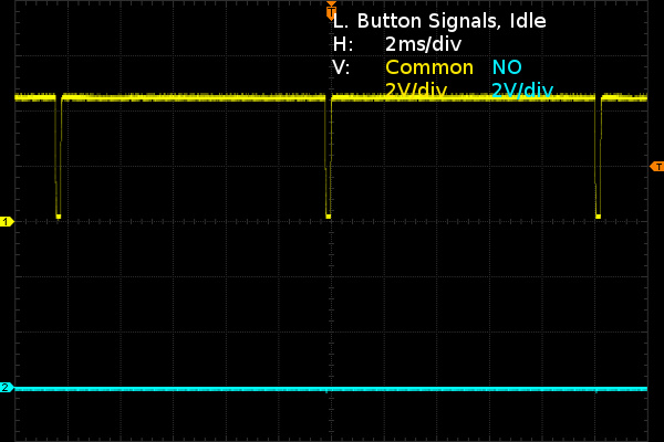
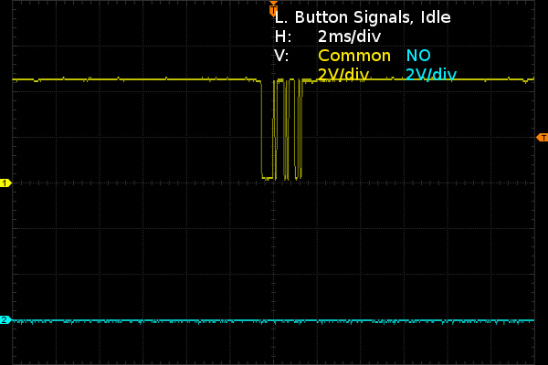
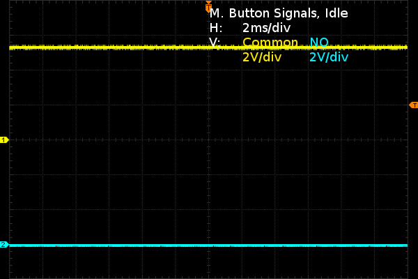
The first slide shows the left button when it's idle. The common contact's signal gets pulsed low for about 200µs every 10ms while nothing is happening on the NO contact's pin. I take this as a first hint that interfacing my own debounce circuit with the switch signal going to the controller is going to be more complicated than directly patching my logic's output into the signal trace. The second slide shows the right mouse button. Based on the pattern, it appears to be somehow connected to one of the PS/2 data lines and reporting every 1.2 seconds when idle. The third slide shows the middle button. There's no funny business to report; it seems to be getting straight 5.2V from the PS/2 cable on the common side. Three buttons, three seemingly different idle behaviors, meaning I'll possibly have to implement three different interfaces between my SR debounce circuit and the mouse.
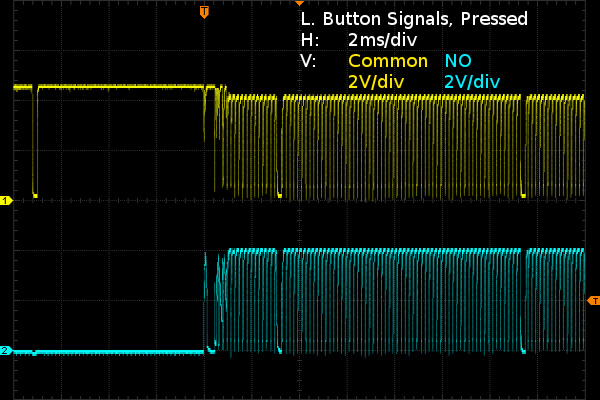
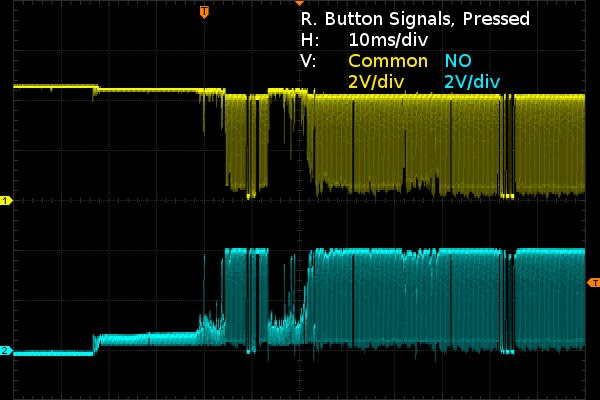
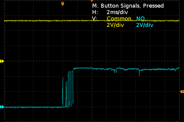
Once the left switch is pressed, something starts pulling the left button signals low at a rate of about 6000Hz while the driver signal still blanks out for 200µs every 10ms, as before. The right switch's signals look mostly similar except for some extremely crusty action as the switch makes poor contact for about 20 of the first 30 milliseconds. We can also see PS/2 packets dropping by to say hello in both the first division after the trigger and the second division from the right. For the middle mouse button, it really is just a switch connecting an input to either supply voltage or ground, which should make it debounceable by simply adding a small capacitor. I wonder: which side of the left and right switches does the controller actually take its left and right button inputs from? The common or NO side? Perhaps zooming in will reveal some clues.
If you thought my right button waveform looked bad, it is actually far from the worst I saw. There were many actuations where the switch failed to make stable contact until I wiggled the plunger or contact would break from doing so. I picked this waveform because it shows a fair sample of both sort-of-good and horrible, which is exactly what SPDT debouncing would help cope with. Another curious detail about the left switch is that its waveform shows some amount of change from the moment the blade presumably leaves the NC side, even though the NC pin is not connected to anything (the DC level rises by 0.4V with another 0.4VPP of noise on top). This could be indicative of a high degree of contamination inside the switch.
According to my multimeter, the right and middle buttons read anywhere from 0.1 to 100 ohms when closed, while the left mouse button typically registers under three ohms. A few dozen clicks a day keep oxidation and other junk away! That doesn't help with mechanical strength though; the left switch has a substantially softer touch than the other two, about half the actuation force. Some of that softening might be attributable to the switch having been taken apart and put back together two or three times.
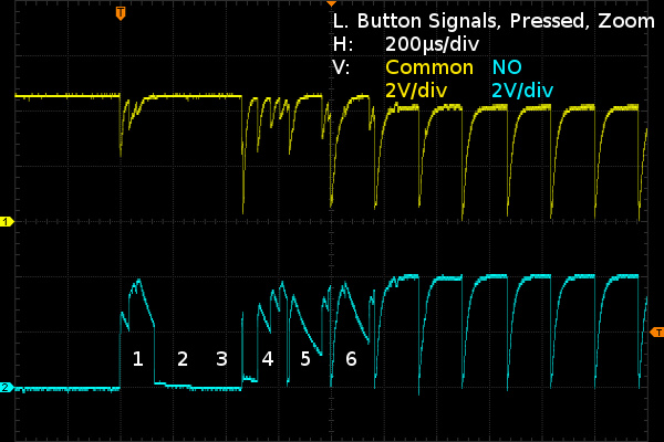
Once the left switch closes and has had a millisecond to settle, those rising edges look distinctly like an RC charge-discharge waveform. The sharp falling edges, on the other hand, look like the timing capacitor gets shorted to ground or reset every 166µs. What is happening there? I'd guess that Logitech is using an open-collector output to periodically reset the capacitor, the idea probably being that on cycles where the switch is still bouncing, the capacitor will fail to reach the threshold voltage between two resets.
On the waveform, we can see the first bounce bring the voltage to nearly 4V, and then decay following what appears to be a typical RC discharge curve for 100µs when contact breaks on the rebound before getting reset. The switch seems to remain open for nearly two whole intervals (except for a lone narrow pulse), bounce four times during the fourth interval, show the distinctive RC charge-discharge waveform through the bulk of intervals five and six and then come clean on subsequent ones.
Get Tom's Hardware's best news and in-depth reviews, straight to your inbox.
Apart from the added periodic timing/filtering capacitor reset, this appears to be fundamentally the same principle as the SPST debounce circuit I mentioned earlier. The controller must be checking some sort of comparator output moments before resetting the capacitor; I would not be surprised if it was used in conjunction with counter-based debouncing. Otherwise, there would be no need to test and reset the switch's detection circuit 6000 times per second or use an RC constant of only 40-50µs.
With that said, I am still no closer to positively identifying which side of the switch the controller takes its inputs from. Time to reverse-engineer the PCB and find out what the left and right switch terminal tie into. In retrospect, I should have taken a preliminary look first, before speculating on how the circuit might be working. With some luck, I may stumble upon an easy debounce tweak for them. After looking at these waveforms, though, I get the feeling that figuring out how to interface an "aftermarket" debouncer could be more trouble than it is worth. So long as I don't ruin the board, at least I can still throw in new switches.
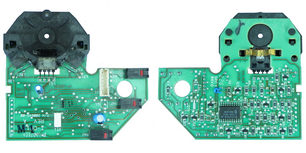
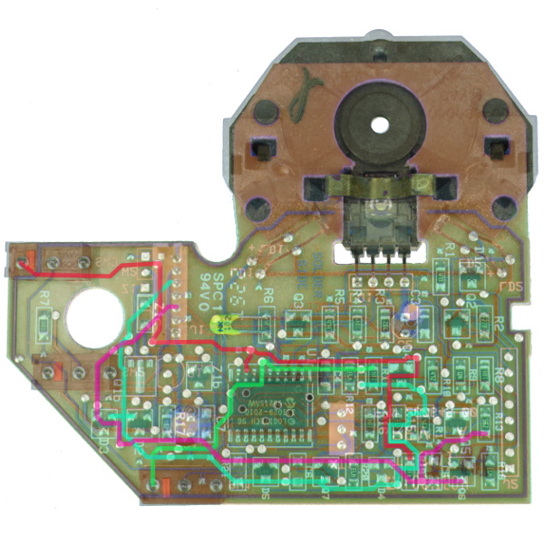
There is not much worth mentioning on the PCB's top side: the three switches, two electrolytic capacitors, the cable connector, the optical sensor and its IR illumination LEDs. The bottom, on the other hand, is packed with a dozen surface-mount resistors, half a dozen SOT23 dual diodes and a similar number of transistors. I was expecting to see a few capacitors in the debounce circuit, but the only two SMD caps I see are used for additional power decoupling at the optical sensor and the controller chip. Although their roles are obfuscated by traces disappearing under the controller chip, other components and silkscreen, there are indeed three unpopulated footprints with a Cn component designation that could be part of the buttons' debounce circuit. It's tempting to associate those surface-mount components with the optical sensor near them, but the sensor's four pins are power, ground and two signal lines that go directly to the controller. There's no connection whatsoever to any of those transistors, diodes and resistors. The guard trace going all around the PCB on both sides connects to the PS/2 connector's shield wire.
How many of these discrete components are related to the switches and how many are for other stuff? Finding out might get a little complicated.
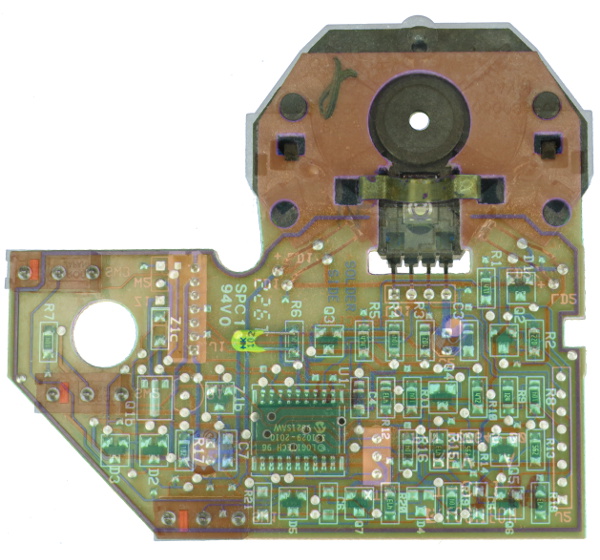
When you want to trace a two-layer circuit board, one useful trick is to take photographs of both sides, scale, rotate, deform and skew them to match as precisely as possible. Put them on two separate layers of the same image, skew the colors on both of them for contrast and tweak layer transparency as needed to make following traces easier.
D2 and D3 are connected to two data pins on the cord connector along with power and ground, so they're nothing more than electrostatic discharge (ESD) protection diodes. Two more traces from the connector go to the component cluster between Q4 and Q5, which must be some discrete bus interface logic for the mouse data and clock pins. Components around Q2 are for the IR LEDs' current source, leaving two transistors and two diode packs unaccounted for.
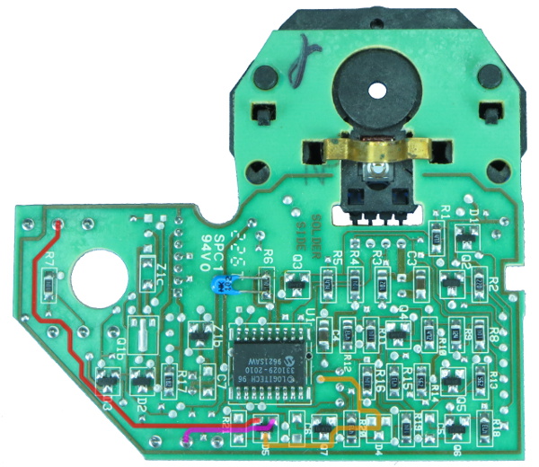
Finding where the “reset” comes from was simple. Everything I needed was on the bottom layer.
The left and right mouse buttons' NO traces, highlighted in red and purple, are routed to separate pins on D6. Then the combined signal trace, highlighted in yellow, disappears under the controller chip to what must be an open-collector or open-drain pin handling the pull-down for both switches. It looks like R21 was intended to provide some degree of baseline pull-down but got omitted. It may have been intended to drain leakage current and ultimately deemed unnecessary. When you have spare space on a PCB, it is cheaper to plan for extra components that might be necessary and leave them unpopulated rather than re-spinning the PCB.
There isn't anything exciting to say about the middle mouse button. Its NO terminal is pulled to ground by R7, a 100kΩ resistor, and its common terminal is wired directly to the supply rail. It does not get much more basic than that.
Things are not so simple on the left mouse button's common contact side…
The red-highlighted trace starts from the left button's common contact, connects to the controller chip as it zips by and continues its half-lap around the PCB to reach R19, a 100kΩ resistor. From the other side of R19, highlighted in purple, it branches out to Q6 and R13, which connects to Q5. Continuing its run around the PCB from R19, it also connects to D3 before reaching pin three on the cable connector. The trace from the right mouse button (in green) disappears under the chip, reappears on its fourth pin from the top-left, and proceeds to R11 from there, which also happens to be a 100kΩ resistor. On the other side of R11 (in cyan), the signal hooks up to Q7 and eventually snakes its way to pin five on the cable connector. Both traces switch sides half a dozen times along their respective paths, often only long enough to jump over a trace or two. All the discrete SOT23 transistors are marked 1AM, which most manufacturers associate with the 2N3904 NPN transistor. Both the left and right mouse buttons indirectly connect to PS/2 signals and have an open-collector transistor on their signal path. I cannot say I am surprised after seeing PS/2 packets appear in the right button's waveforms. Some PS/2 traffic is present on the left button's signals too, albeit much less frequently.
With the two switches partially traced out on both contacts, I now have a reasonably good idea of how the switch detection actually works. The controller simply looks for the pin associated with each switch getting pulled low by what I thought was intended to be an RC reset signal. The RC-like behavior turned out to be nothing more than the weak pull-up resistor interacting with stray circuit capacitance. There is no analog debouncing whatsoever happening here. Was saving one or two pins on the controller worth all the extra layout effort, discrete parts and complexity? I doubt it.
At least now I should have all the information I need to interface external logic with the mouse's switch signals.
-
SirGCal My problem with my MS is just finding a mouse I can use well period.I have some mice like this trackball myself and still can't use it properly. I need one controlled with the mind instead of hand. Which is probably coming sooner then we think.Reply -
theaudiophile Holy shit, you're crazy in many many ways. I am an electronics hobbyist myself, and you sir are simply insane. I hope this article gets enough traffic and ad clicks to make up for the time you put in instead of replacing switches.Reply -
mikesinner Both me and a friend of mine have already bought new mice, but I did keep the old one, a logitech G700 with the terribly annoying double click glitch when only single clicking. It's not a very old mouse either, so I find it very disturbing that the switch is already worn!Reply -
Daniel Sauvageau Reply
You give me too much credit. This is a simple hack once you know what you are dealing with - finding out what you have to work with is usually the most tedious part of a modification job, especially when you don't have design schematics or someone else's instructions to start from.17690562 said:Holy shit, you're crazy in many many ways. I am an electronics hobbyist myself, and you sir are simply insane.
The hack might be more trouble than it is worth but it does show that there is no reason for mouse buttons with SPDT switches to glitch until the switch mechanically fails. Other than mice manufacturers choosing to design them this that way that is.
My G500S is about four years old and the glitching is at that early stage where I'm not sure if the glitches are caused by the mouse or by mouse movement when I click.17690678 said:Both me and a friend of mine have already bought new mice, but I did keep the old one, a logitech G700 with the terribly annoying double click glitch when only single clicking. It's not a very old mouse either, so I find it very disturbing that the switch is already worn!
-
BulkZerker http://www.epicpants.com/t-shirts/tek-syndicate-gaming-mouse-standard-issueReply
Problem solved.
-
razor512 Wouldn't it be easier to just use hall effect switches (like with some industrial machines)?Reply
The switches can be magnetically shielded, and as long as the button actuation functions (no broken springs), the button will continue to work, along with any vibrations of the actuation being calibrated out in software. -
buzzrattie Wish there were a mouse that was cat-hair proof. Dang little buggers shedding all the time, and getting into the laser.Reply -
Daniel Sauvageau Reply
I doubt switches that require additional calibration steps would be popular in a market where manufacturers are trying to optimize every penny of profit they think they can get away with out of their product.17691040 said:Wouldn't it be easier to just use hall effect switches (like with some industrial machines)?
The switches can be magnetically shielded, and as long as the button actuation functions (no broken springs), the button will continue to work, along with any vibrations of the actuation being calibrated out in software.
One option which does not require calibration is optical sensing: poke a slotted stem through the detector. Most mechanical mice used optical wheel encoders to convert ball motion to digital. The same thing could be done for switches.
I doubt either option would be as inexpensive as a mechanical switch and with the "memory" version of my hack, it would be a practically free fix. Free is a tough price to beat.
