Hacking Your Mouse To Fix The Misclick Of Doom
Ever had your patience put on trial by glitchy mouse buttons? That is one problem that simply should never have been on any half-decent mice.
The Hack
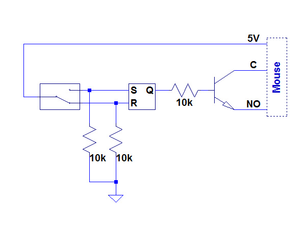
To interface my own “aftermarket” debounce circuit, I need to read the sink pulse from the NO contacts and only drive the common side of the switch low during that time when my debounce is in the 'set' state. How do you combine the need for an open-collector/drain output, the need to synchronize your output driver with a sink signal and the output from an SR latch? After imagining a few convoluted schemes, I eventually reduced my solution to the following:
Originally, I was thinking of digging through my parts bin to see if I happened to have an open-collector inverting buffer with active-low enable pin, but instead decided to build one using transistors and resistors. Then I realized that I could eliminate the need to provide my own active-low enable circuit by taking advantage of the mouse's open-collector sink pulse on the left and right switches' NO pin. That let me reduce the circuit to a simple 2N3904 and a 10kΩ resistor. When the RS latch output is low, the transistor is off and nothing happens. When the RS latch is set, the collector/common pin follows whatever is on the emitter/NO pin. The only thing simpler than this is the middle mouse button, which can interface directly with the RS output.
Now it's time to hook it up to the PCB and see if the inputs and outputs are compatible with their intended targets.
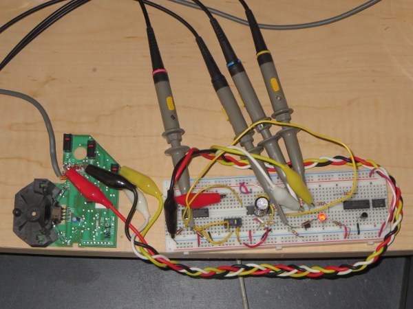
Four alligator clip leads connect the mouse's PCB to my breadboarded debounced switch. Red and black bring power and ground from the PS/2 cable connector to the breadboard, while white and yellow carry the right switch's common and NO contact signals, respectively. As before, my first two scope probes are connected to the common and NO signals of the mouse's switch (on the breadboard instead of the mouse this time). The other two channels are connected to the raw NO switch contact and RS latch output.
Pressing the switch on the breadboard does make the context menu pop up on my PC, which immediately tells me that my little interface circuit worked. This is always a good first sign.
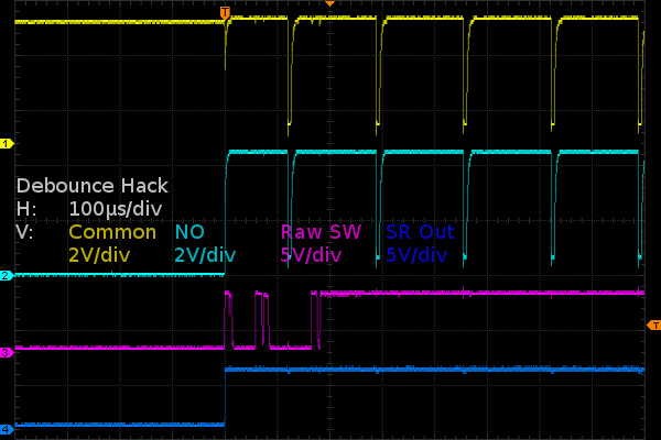
Once the first raw switch pulse (purple trace) hits the SR latch, the SR latch's output (dark blue trace) goes high. The debouncing circuit leaves the common signal (yellow) alone until the NO trace (cyan) goes low, which turns the NPN transistor on and drags the collector/common side down with it. Interfacing the RS debounce with the mouse's circuitry turned out much simpler than I initially thought it would be.
Now that the whole thing checks out in principle, the last few steps are shoving the circuit on a PCB, severing the switches' traces on the mouse so I can re-wire them for my purposes and attaching the mod wires necessary to connect the NO/NC contacts, the button signal traces, the sink signal, power and ground.
Get Tom's Hardware's best news and in-depth reviews, straight to your inbox.
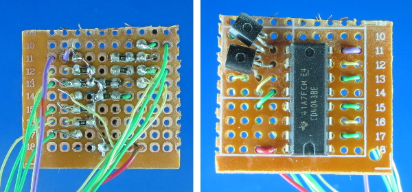
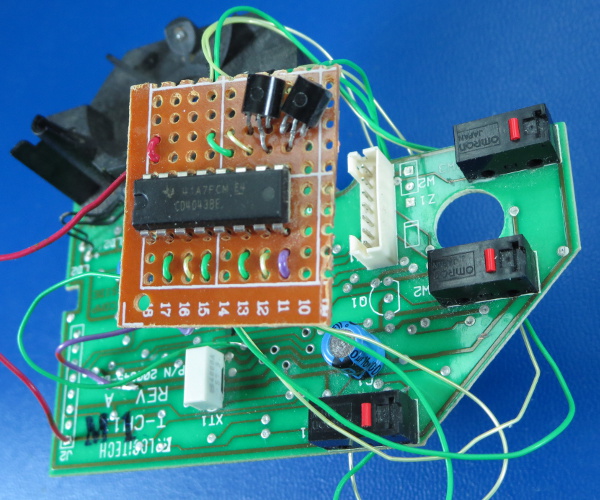
Instead of designing the circuit in CAD software, paying $10 to get the boards printed, waiting for a month to receive them and put one together, I chose to use a piece of 0.1” pitch perforated prototype board with solder pads. As you may have noticed, there are no resistors on top. Since 0805-size surface mount components fit snugly between holes, I decided to use surface mount resistors on the bottom to make the circuit more compact. I was not intending for my two 2N3904 to be face-down on the PCB, but after accidentally smashing them while handling the board, I decided it was safer to leave them that way (after checking that there was no short) than risk breaking leads by bending them back. That made me wish I had SOT23 ones instead of TO92s. For strain relief, and to help keep wires in place for soldering, I looped all of my mod wires through two nearby holes.
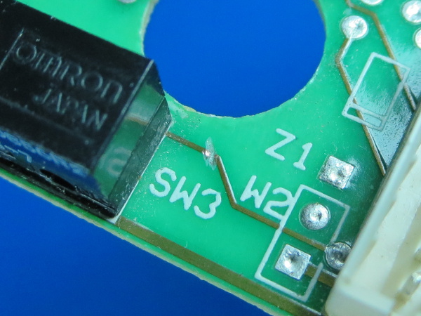
The next part involves locating every trace connected to the switch contacts and cutting them. Three switches, two traces each; that's six cuts. I used a high-speed rotary tool and the smallest router bit I had to grind a small piece of the offending traces off. Since the large router bit meant I could not see the cuts, I had to gauge whether the bit had chewed through the trace by feel.
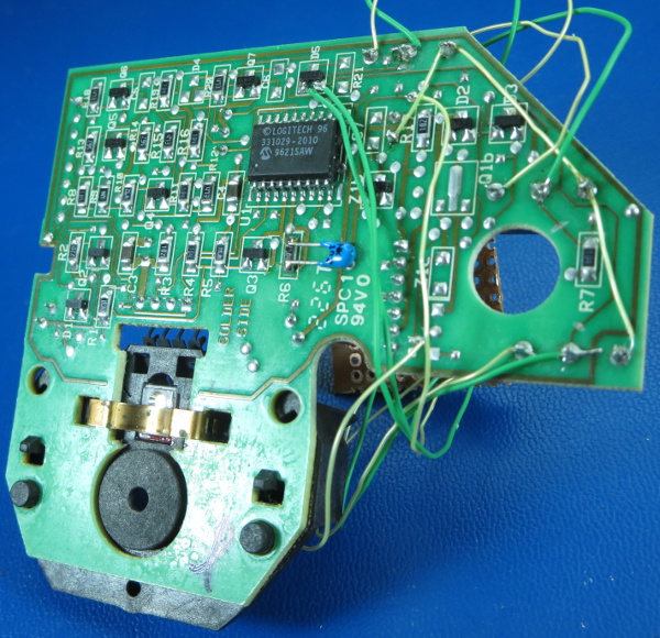
Having only two mod wire colors probably wasn't a great choice, and cutting my wires to the same length before picking an install location did not help keep things tidy. From the bottom-right corner and running along the switches' common contacts, you can see the mod wire bringing 5V to the three switches. You can also see the green and yellow wires for each of the NO and NC contacts. The other two yellow and green pairs are the collectors and emitters from the 2N3904 button signal interface.
We're all wired up and ready for a test drive. I may not score many points for neatness, but as long as it works, I'm happy. Nobody will know what this looks like once it's hot-glued down to the original PCB and the cover is screwed back on. Though, at this point, I am a little worried that I didn't give myself enough slack in the mod wires to clear the right switch and its associated parts on the top cover.
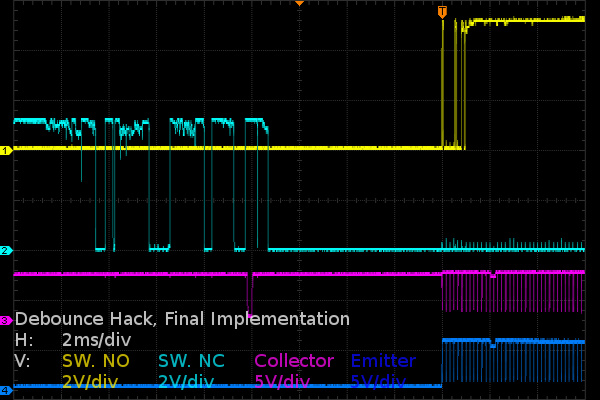
And here is one last set of waveforms, just to verify that there is no funny business going on. I am monitoring both of the right switch's physical contacts, along with its companion transistor's collector and emitter to verify that it still works as expected. Unsurprisingly, it does.
With my hack complete, all that is left to do is secure the wires and PCB with hot glue before putting the cover back on.
-
SirGCal My problem with my MS is just finding a mouse I can use well period.I have some mice like this trackball myself and still can't use it properly. I need one controlled with the mind instead of hand. Which is probably coming sooner then we think.Reply -
theaudiophile Holy shit, you're crazy in many many ways. I am an electronics hobbyist myself, and you sir are simply insane. I hope this article gets enough traffic and ad clicks to make up for the time you put in instead of replacing switches.Reply -
mikesinner Both me and a friend of mine have already bought new mice, but I did keep the old one, a logitech G700 with the terribly annoying double click glitch when only single clicking. It's not a very old mouse either, so I find it very disturbing that the switch is already worn!Reply -
Daniel Sauvageau Reply
You give me too much credit. This is a simple hack once you know what you are dealing with - finding out what you have to work with is usually the most tedious part of a modification job, especially when you don't have design schematics or someone else's instructions to start from.17690562 said:Holy shit, you're crazy in many many ways. I am an electronics hobbyist myself, and you sir are simply insane.
The hack might be more trouble than it is worth but it does show that there is no reason for mouse buttons with SPDT switches to glitch until the switch mechanically fails. Other than mice manufacturers choosing to design them this that way that is.
My G500S is about four years old and the glitching is at that early stage where I'm not sure if the glitches are caused by the mouse or by mouse movement when I click.17690678 said:Both me and a friend of mine have already bought new mice, but I did keep the old one, a logitech G700 with the terribly annoying double click glitch when only single clicking. It's not a very old mouse either, so I find it very disturbing that the switch is already worn!
-
BulkZerker http://www.epicpants.com/t-shirts/tek-syndicate-gaming-mouse-standard-issueReply
Problem solved.
-
razor512 Wouldn't it be easier to just use hall effect switches (like with some industrial machines)?Reply
The switches can be magnetically shielded, and as long as the button actuation functions (no broken springs), the button will continue to work, along with any vibrations of the actuation being calibrated out in software. -
buzzrattie Wish there were a mouse that was cat-hair proof. Dang little buggers shedding all the time, and getting into the laser.Reply -
Daniel Sauvageau Reply
I doubt switches that require additional calibration steps would be popular in a market where manufacturers are trying to optimize every penny of profit they think they can get away with out of their product.17691040 said:Wouldn't it be easier to just use hall effect switches (like with some industrial machines)?
The switches can be magnetically shielded, and as long as the button actuation functions (no broken springs), the button will continue to work, along with any vibrations of the actuation being calibrated out in software.
One option which does not require calibration is optical sensing: poke a slotted stem through the detector. Most mechanical mice used optical wheel encoders to convert ball motion to digital. The same thing could be done for switches.
I doubt either option would be as inexpensive as a mechanical switch and with the "memory" version of my hack, it would be a practically free fix. Free is a tough price to beat.
