Thermaltake Toughpower DPS G 1200W PSU Review
Thermaltake introduced the Toughpower DPS G Platinum line that consists of three new, semi-digital and fully modular PSUs made by Enhance Electronics. The highest-capacity 1200W model is our test subject in today's review.
Why you can trust Tom's Hardware
A Look Inside And Component Analysis
Parts Description
Before proceeding with this page, we strongly encourage you to a look at our PSUs 101 article, which provides valuable information about PSUs and their operation, allowing you to better understand the components we're about to discuss. Our main tools for disassembling PSUs are a Thermaltronics soldering and rework station, and a Hakko 808 desoldering gun.
| Primary Side | |
|---|---|
| Transient Filter | 4x Y caps, 4x X caps, 2x CM chokes, 1x MOV |
| Inrush Protection | NTC Thermistor & Thermistor |
| Bridge Rectifier(s) | 2x GBU15L06 (600V, 15A @ 115 °C) |
| APFC MOSFETs | 2x Infineon IPW60R099C6 (650V, 24A @ 100 °C, 0.099Ω) |
| APFC Boost Diode | 1x CREE C3D10060A (600V, 10A @ 153 °C) |
| Hold-up Cap(s) | 2x Matsushita/Panasonic (420V, 470uF each or 940uF combined, 2000h @ 105 °C, HC) |
| Main Switchers | 4x Infineon IPP60R160C6 (650V, 15A @ 100 °C, 0.16Ω) |
| Driver ICs | 2x Silicon Labs Si8230BD |
| APFC Controller | Champion CM6502S & CM03X Green PFC controller |
| Switching Controller | Champion CM6901 |
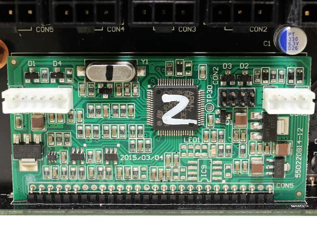
| MCU | STMicroelectronics STM32F302 (ARM 32-bit Cortex-M4 @ 72MHz, 32KB, 12-bit DAC, USB 2.0 interface, temperature sensor) |
| Topology | Primary side: Full-Bridge & LLC Resonant Converter Secondary side: Synchronous Rectification & DC-DC converters |
| Secondary Side | |
| +12V MOSFETs | 12x Infineon BSC014N04LS (40V, 100A @ 100 °C, 1.4mΩ) |
| 5V & 3.3V | DC-DC Converters: 2x Infineon BSC050NE2LS(25V, 37A @ 100 °C, 5mΩ), 2x Infineon BSC018NE2LS (25V, 97A @ 100 °C, 1.8mΩ) PWM Controller: ANPEC APW7073 |
| Filtering Capacitors | Electrolytics: Nippon Chemi-Con (105 °C, KY, KZH), Rubycon (ZLJ, 6000-10000h & 105 °C) Polymers: Teapo, Duratech |
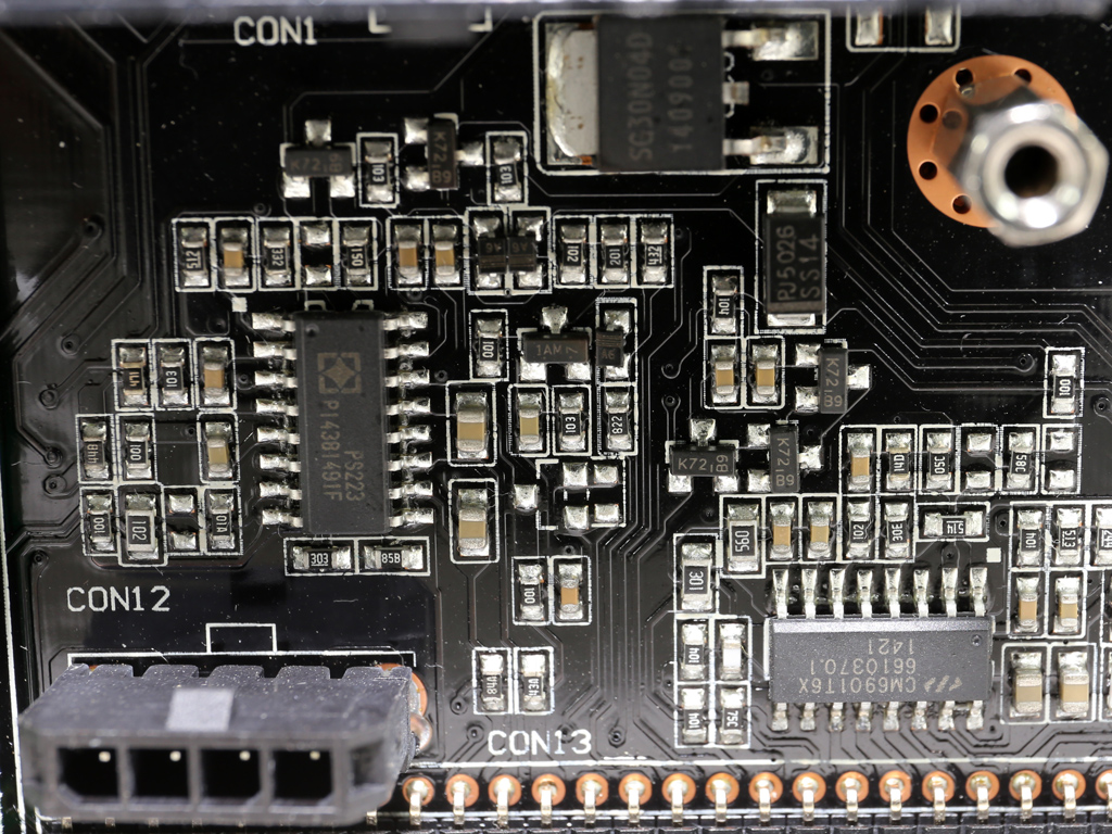
| Supervisor IC | SITI PS223 (OVP, UVP, OCP, SCP, OTP ) |
| Fan Model | TT-1325 (Yate Loon, D14BH-12, 140mm, 12V, 0.70A, 2800RPM, 140 CFM, 48.5 dB[A], double ball-bearing) |
| 5VSB Circuit | |
| Rectifier | 1x PFR10V45CT (45V, 2 x 5A, 0.35V @ 5A & 125 °C) |
| Standby PWM Controller | Sanken STR-A6062H (23W @ 230VAC, 18W @ Universal) |
| -12V Circuit | |
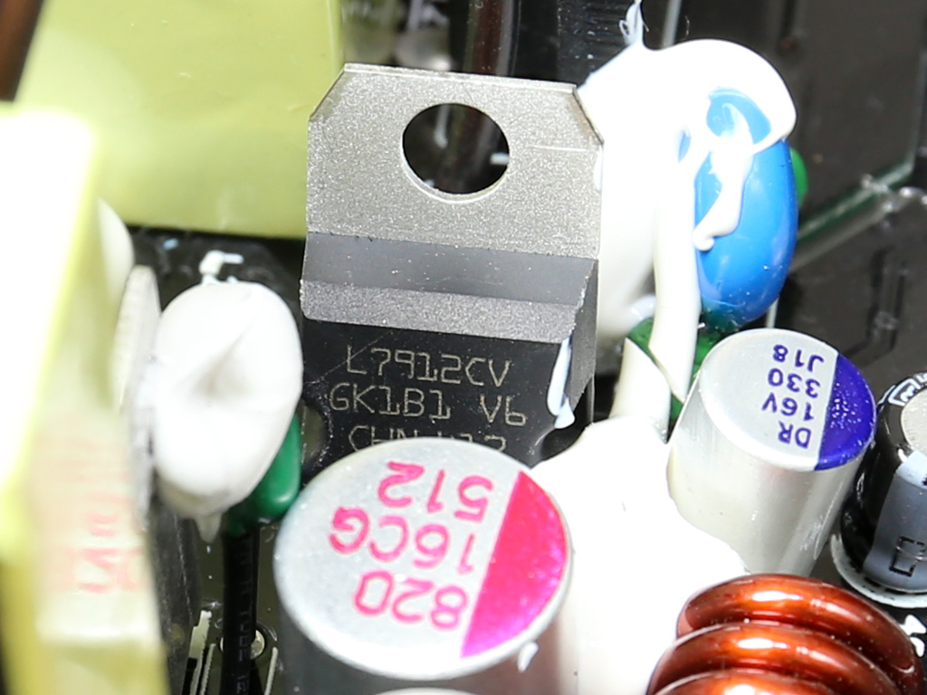
| Regulator | L7912CV (-12V, 1.5A, TO-220) |
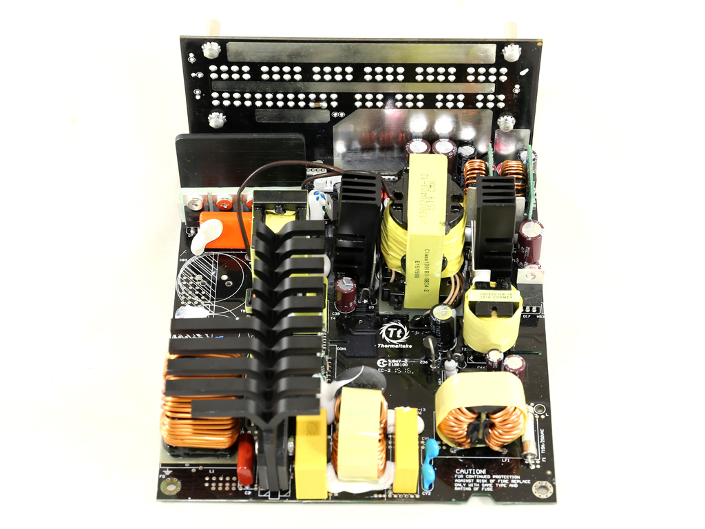
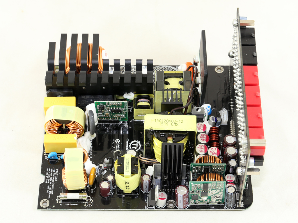
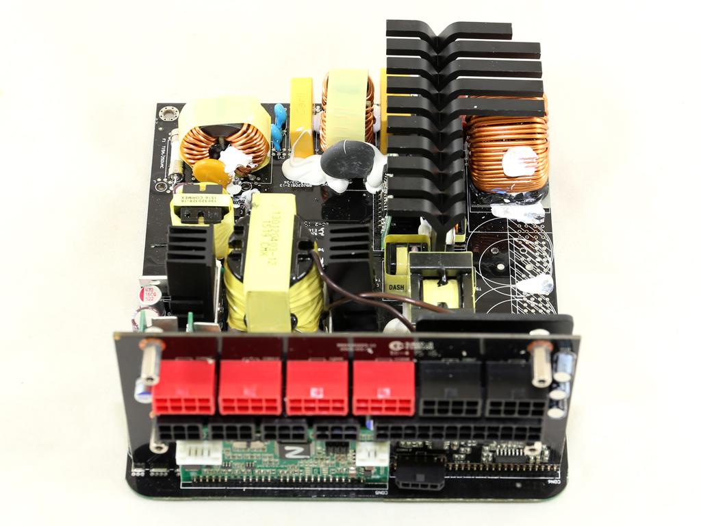
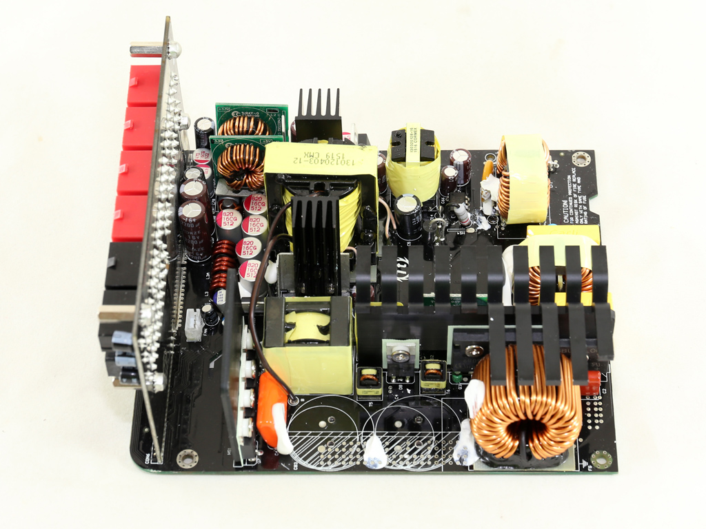
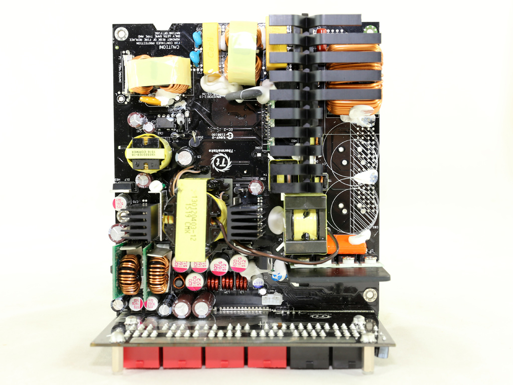
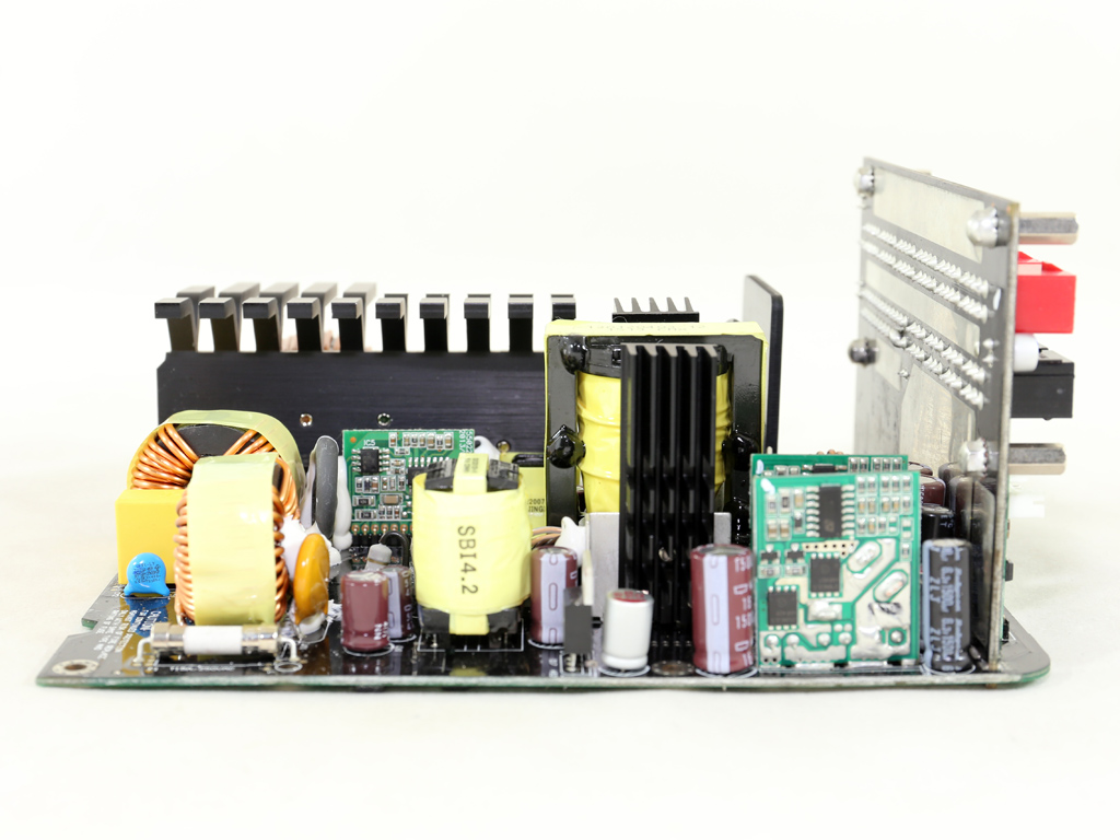
As mentioned, Enhance Electronics is this PSU's manufacturer. Although this is a modern platform, the PCB is notably under-populated, which looks strange in a high-capacity design. We find a full-bridge topology on the primary side, along with an LLC resonant converter. A synchronous design is used on the secondary side, while two DC-DC converters generate the minor rails. Thermaltake ordered Enhance to use only Japanese electrolytic caps for increased reliability, and a number of polymer caps are used for filtering purposes.
The design is clean, allowing ample space between components for increased airflow. Enhance uses a large heat sink on the primary side with its distinct fin design. There are no large heat sinks on the secondary side since the +12V FETs are cooled mostly by the chassis. There is also a smaller heat sink on the primary side for cooling the primary FETs.
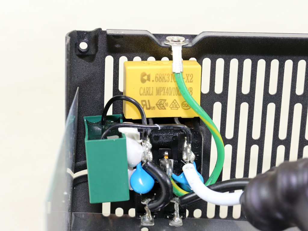
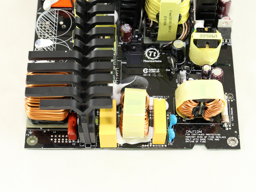
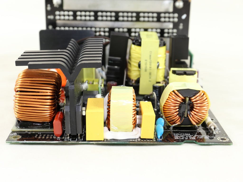
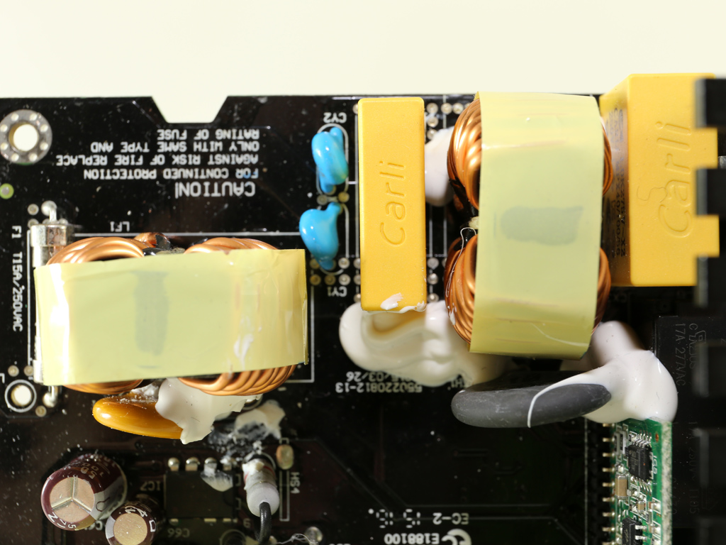
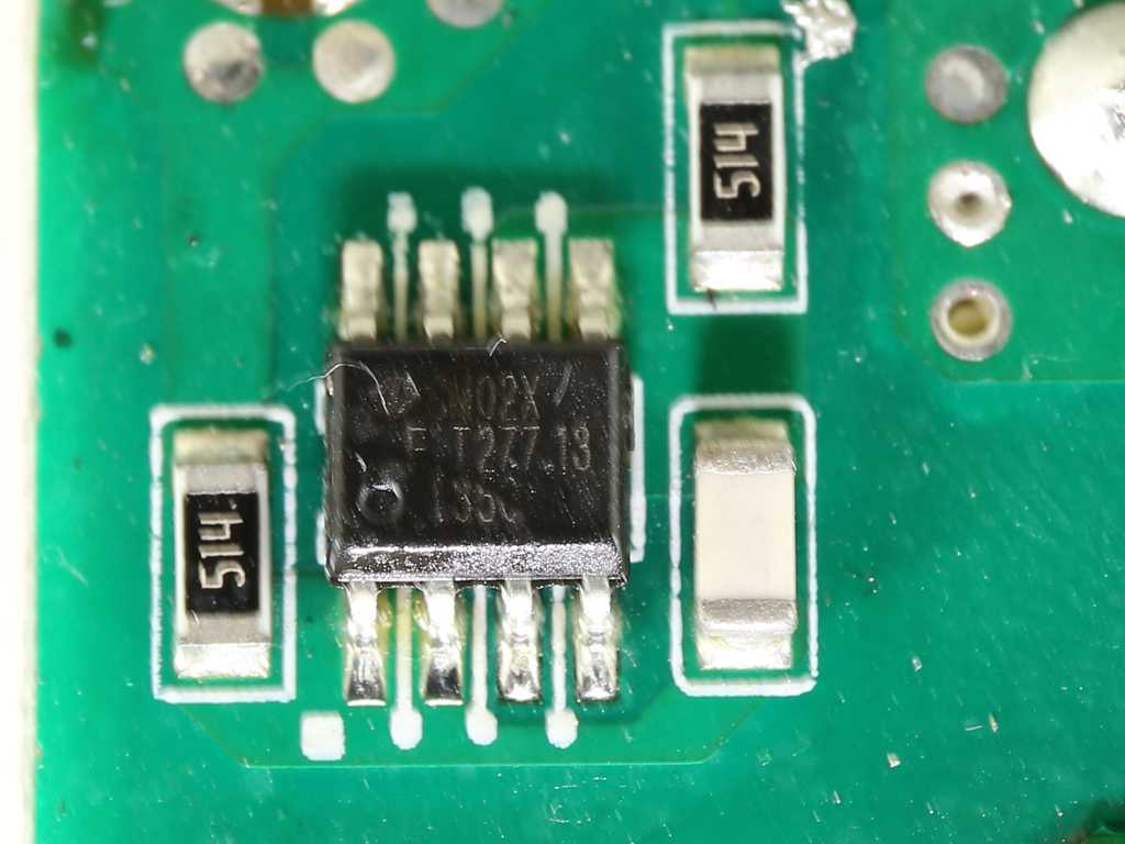
The transient filter starts at the AC receptacle with two X and two Y caps. It continues on the main PCB with two more X and two additional Y caps, two CM chokes and a metal oxide varistor. On the PCB's solder side is a CM02X IC, which blocks current through the X cap discharge resistor when AC voltage is connected and automatically discharges the aforementioned cap through the discharge resistor when AC is disconnected. This method provides a small efficiency boost since no energy is lost on bleeding resistors.
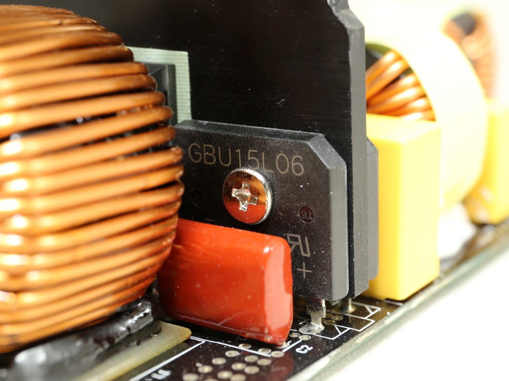
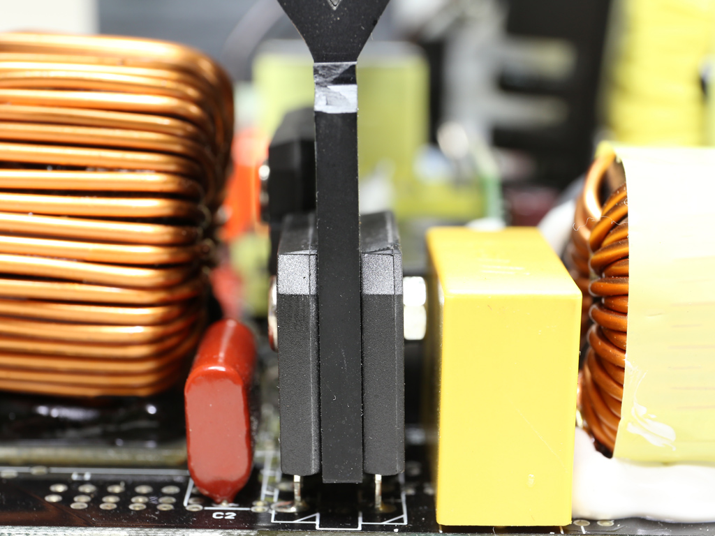
The bridge rectifiers (GBU15L06) are able to handle up to 30A of current. By using two of them in parallel, energy losses are limited since each bridge handles half of the incoming current. This is an easy way to improve efficiency. However, bridge rectifiers don't come cheap, so production cost rises as well.
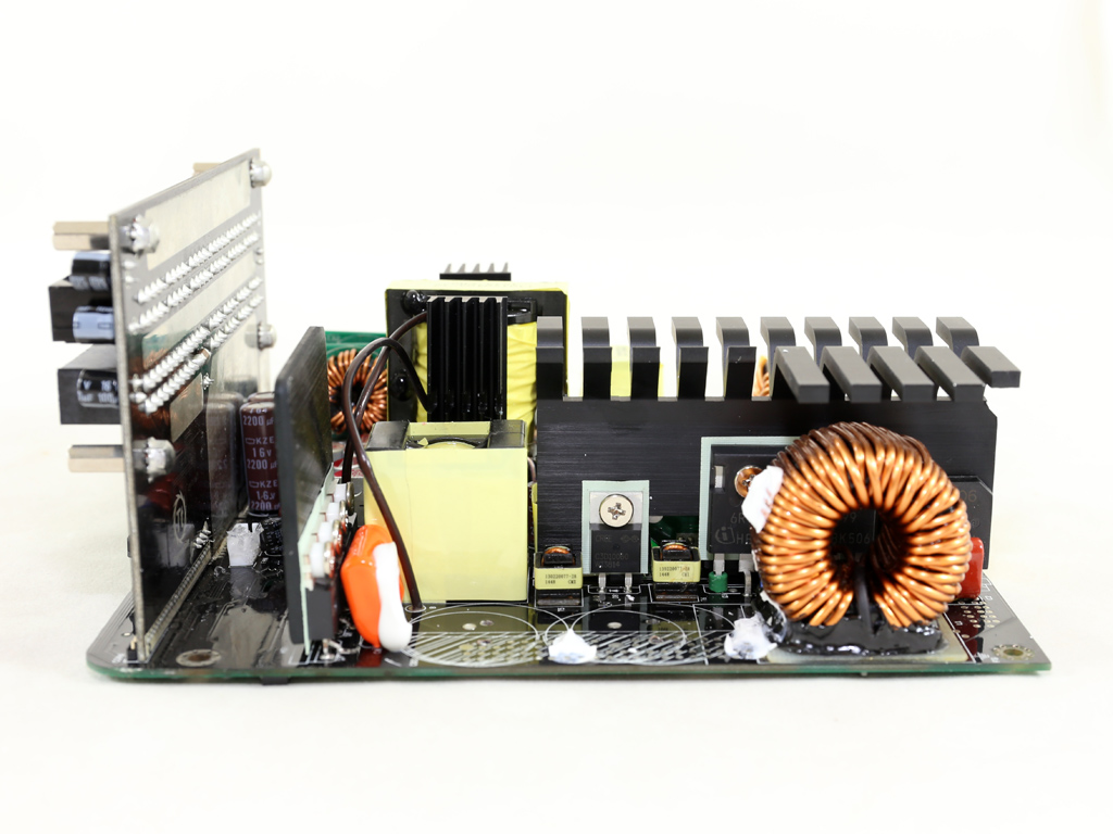
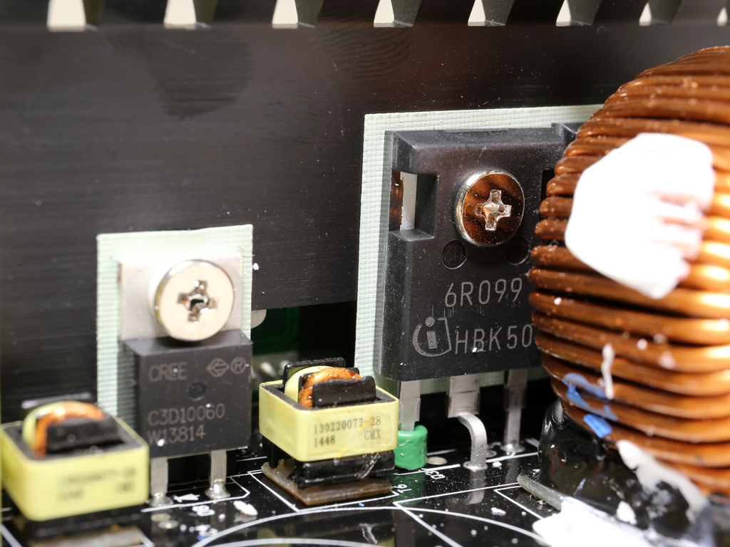
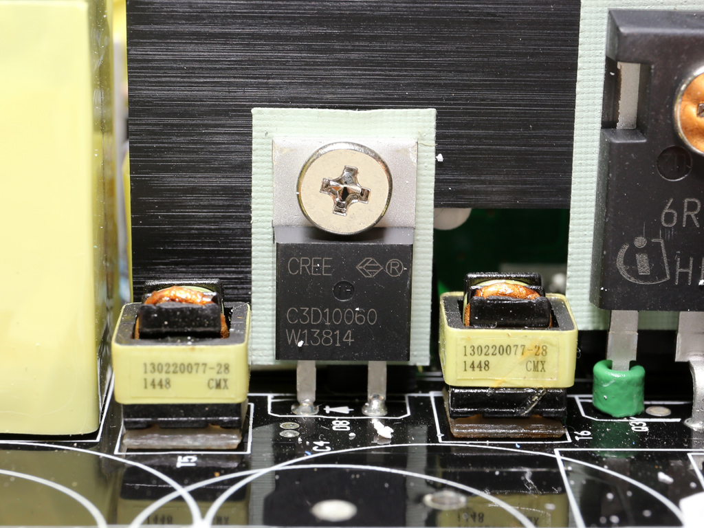
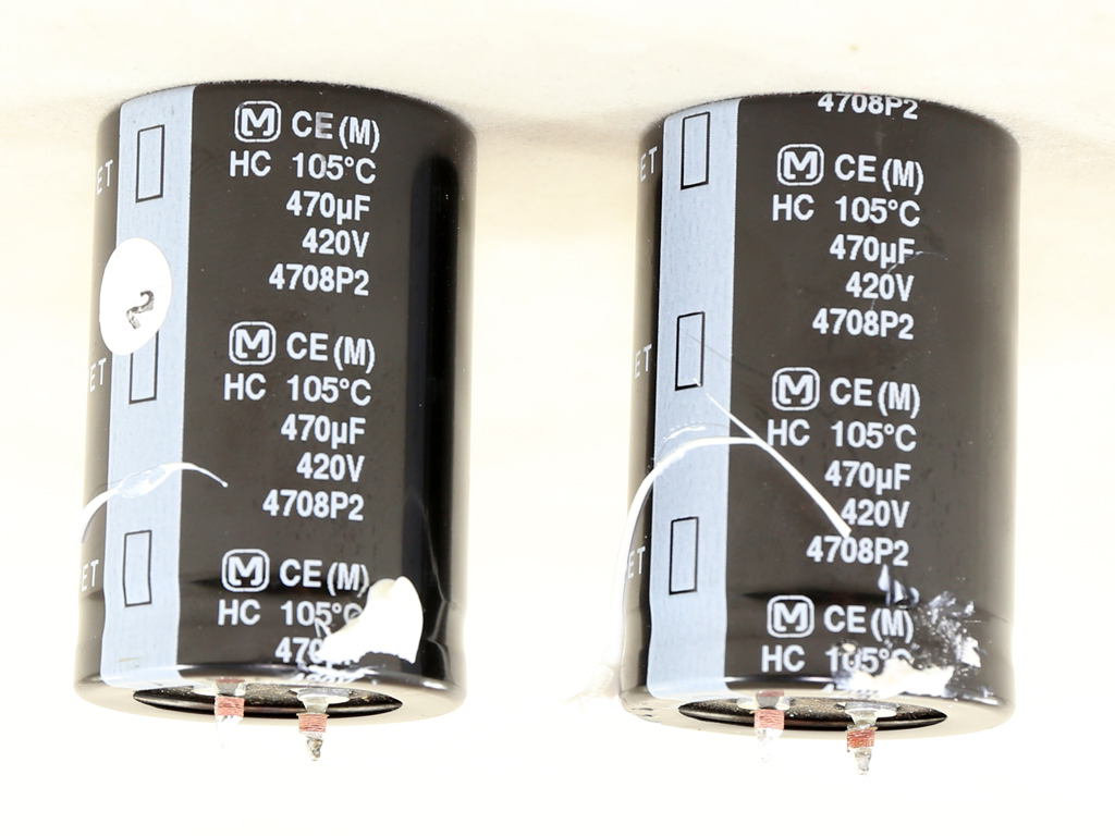
In the APFC converter we find two Infineon IPW60R099C6 FETs and a single CREE C3D10060A boost diode. The pair of parallel bulk caps is provided by Matsushita/Panasonic, and its combined capacity reaches 940uF. Their voltage and temperature ratings are pretty high, so they won't compromise the PSU's reliability.
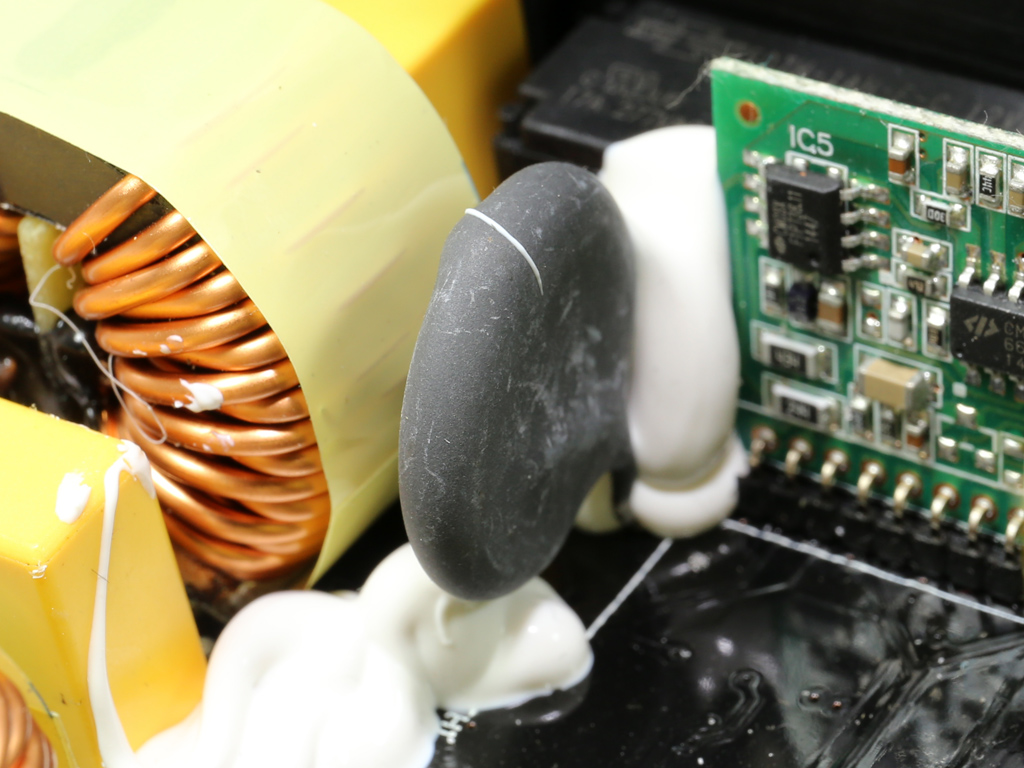
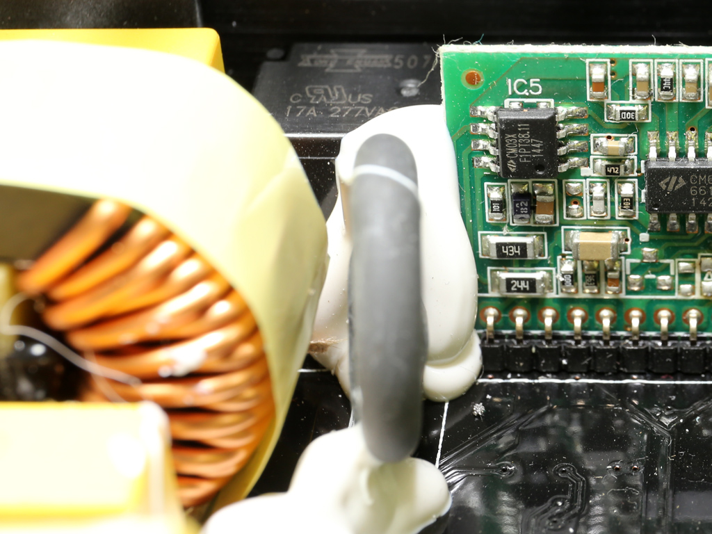
An NTC thermistor protects against large inrush currents. It is supported by a bypass relay, which, besides increasing efficiency, also helps it cool more quickly. A hot NTC thermistor has very low resistance, so it cannot lower the current that the bulk caps demand during the PSU's start-up phase in order to charge rapidly.
Get Tom's Hardware's best news and in-depth reviews, straight to your inbox.
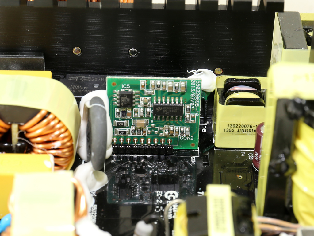
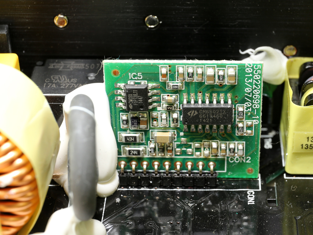
The APFC controller is a Champion CM6502S IC, which is backed by a CM03X Green PFC controller responsible for dropping power consumption below 0.5W in standby. Both controllers are installed onto a small vertical board.
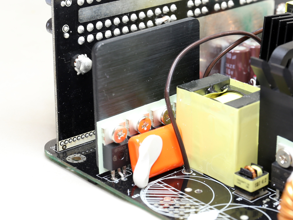
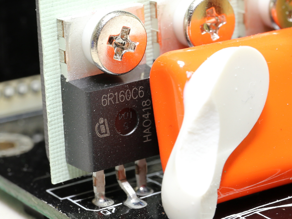
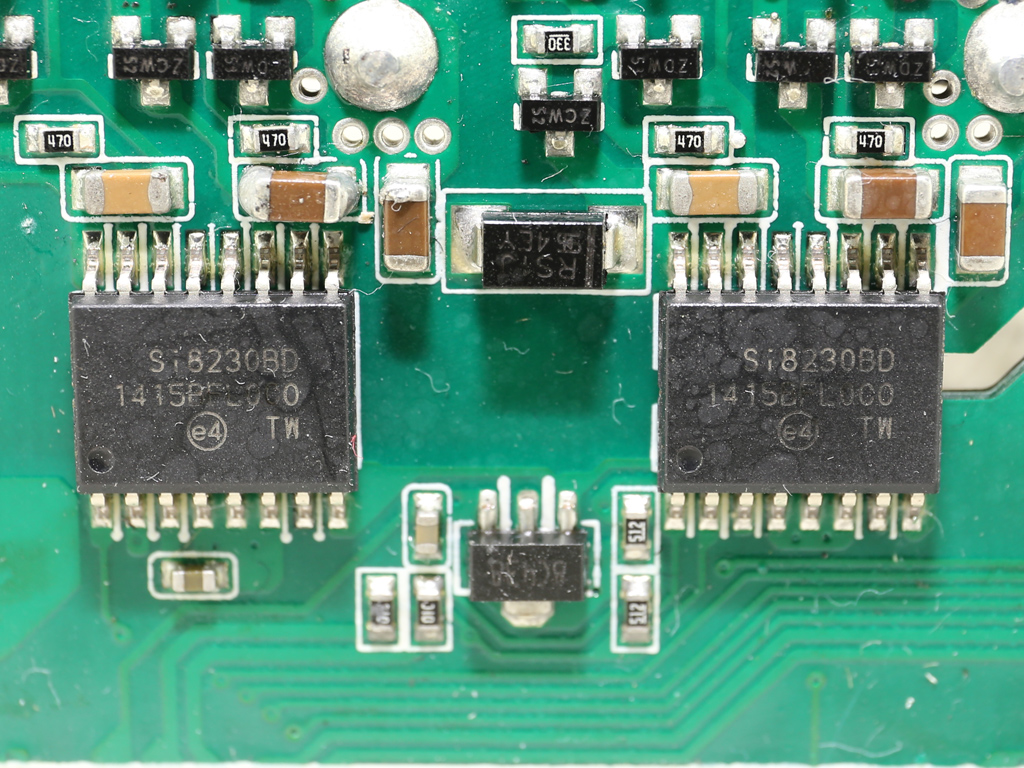
The primary FETs are four Infineon IPP60R160C6s arranged into a full bridge topology. They are installed on a heat sink without fins (strange for an Enhance platform). A couple of Silicon Labs Si8230BD isolated drivers are used for driving the main FETs.
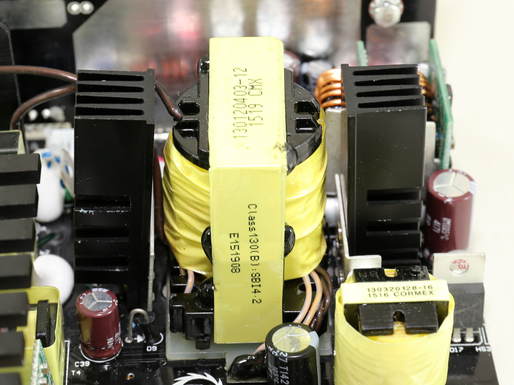
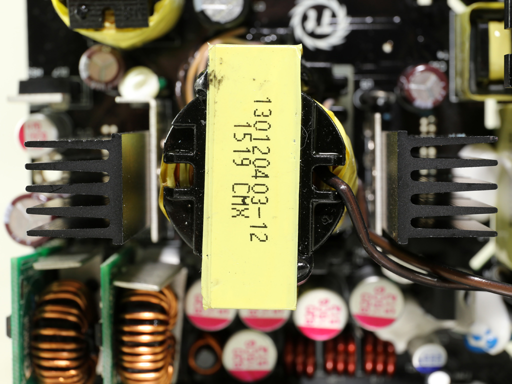
The main transformer is too small for such a high-capacity PSU. It definitely uses a special design to cope with such a formidable load.
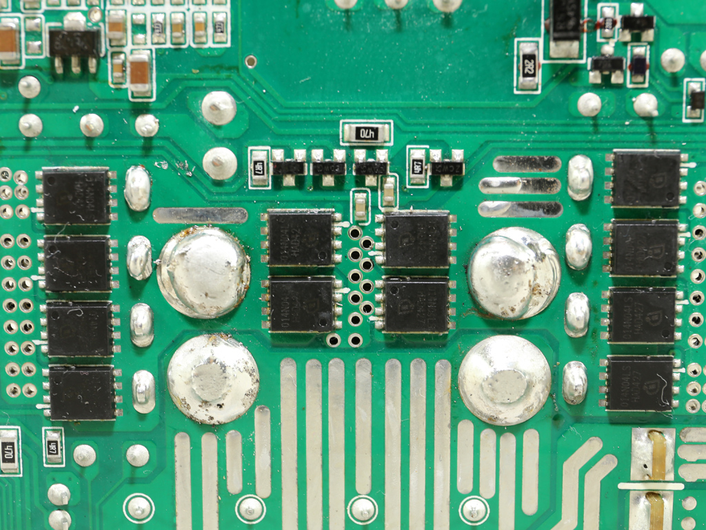
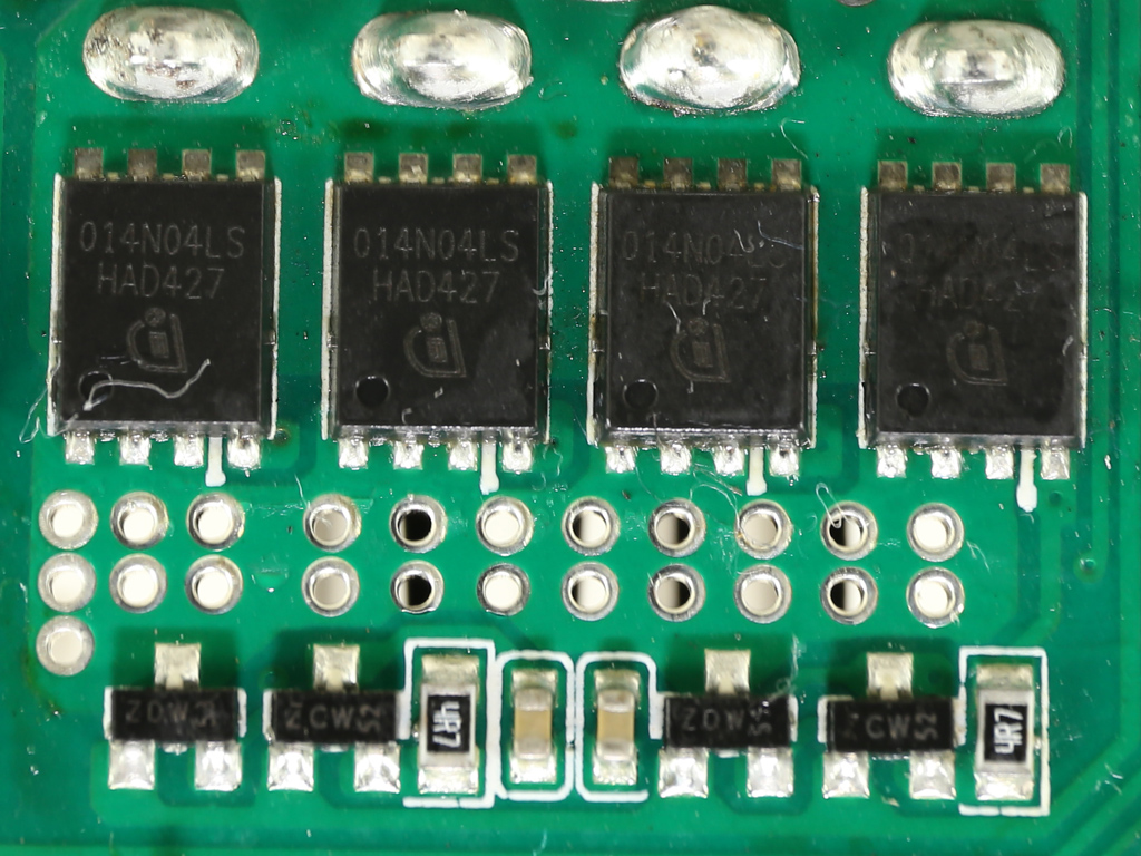
A dozen strong FETs (Infineon BSC014N04LS) generate the +12V rail. They're all installed on the solder side of the PCB, and aside from the two small heat sinks above them, on the component side of the PCB, the chassis also helps keep them cool.
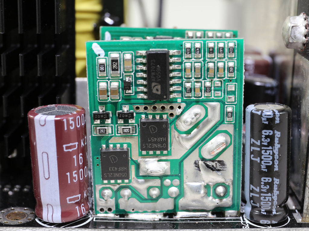
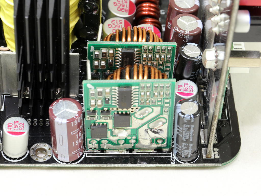
Two small DC-DC converters regulate the minor rails (5V and 3.3V). Each converter uses an ANPEC APW7073 PWM controller along with two Infineon FETs (1x BSC050NE2LS, 1x BSC018NE2LS).
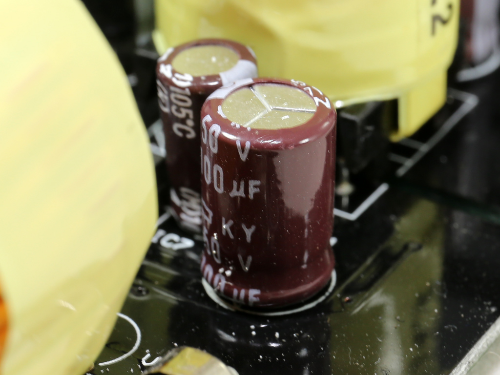
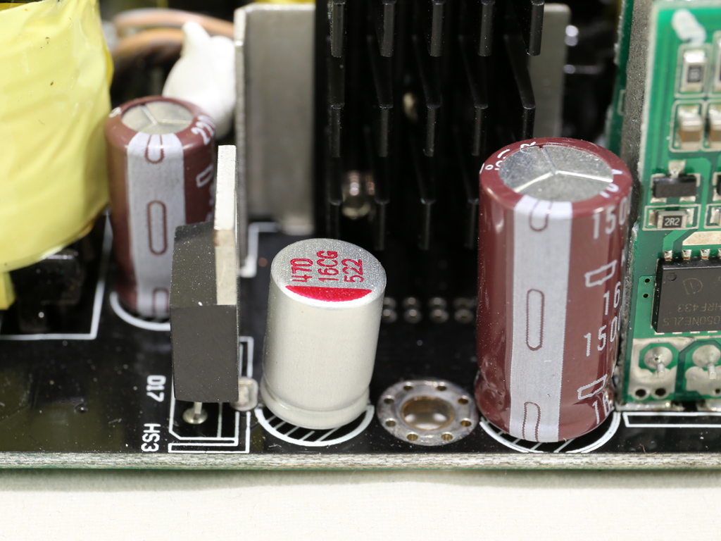
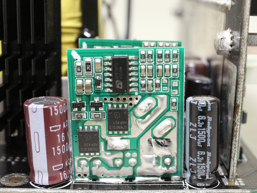
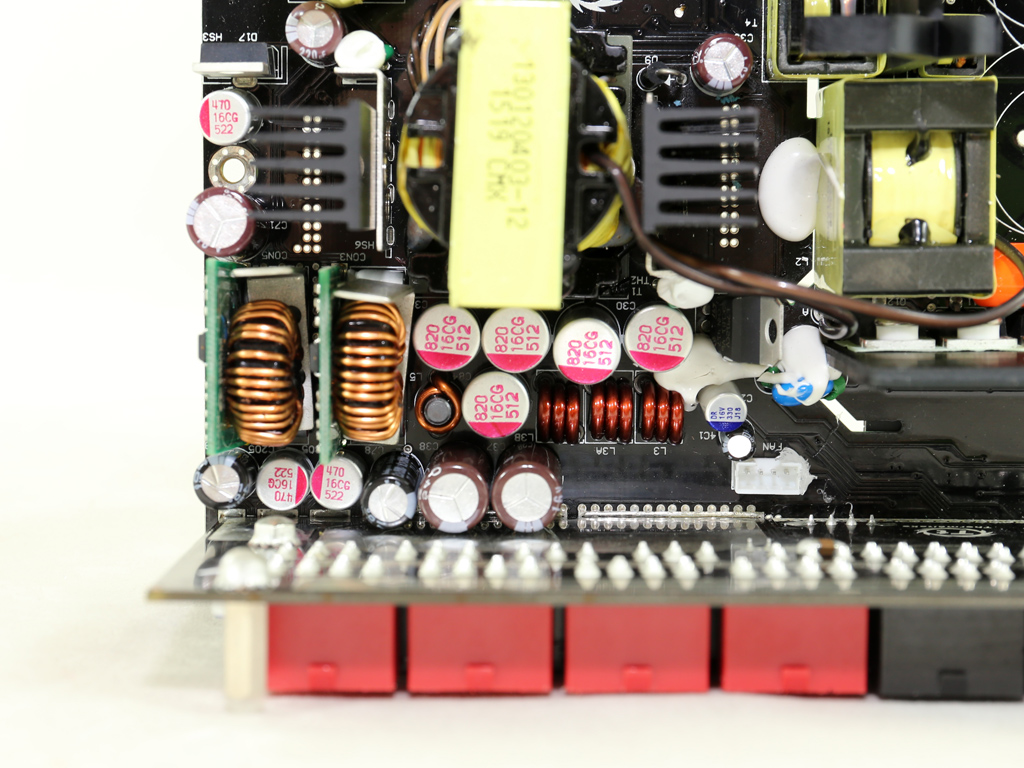
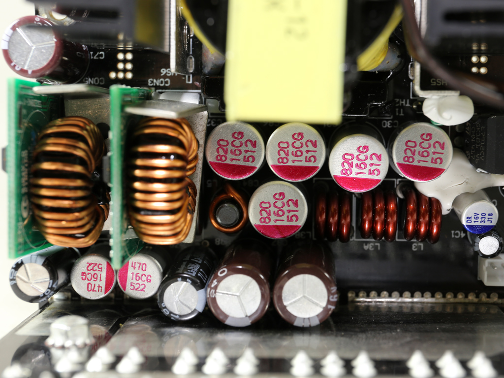
Both polymer (Teapo) and electrolytic (Chemi-Con, Rubycon) caps filter the rails on the secondary side. All electrolytic caps are rated at 105 degrees C for increased lifetime.
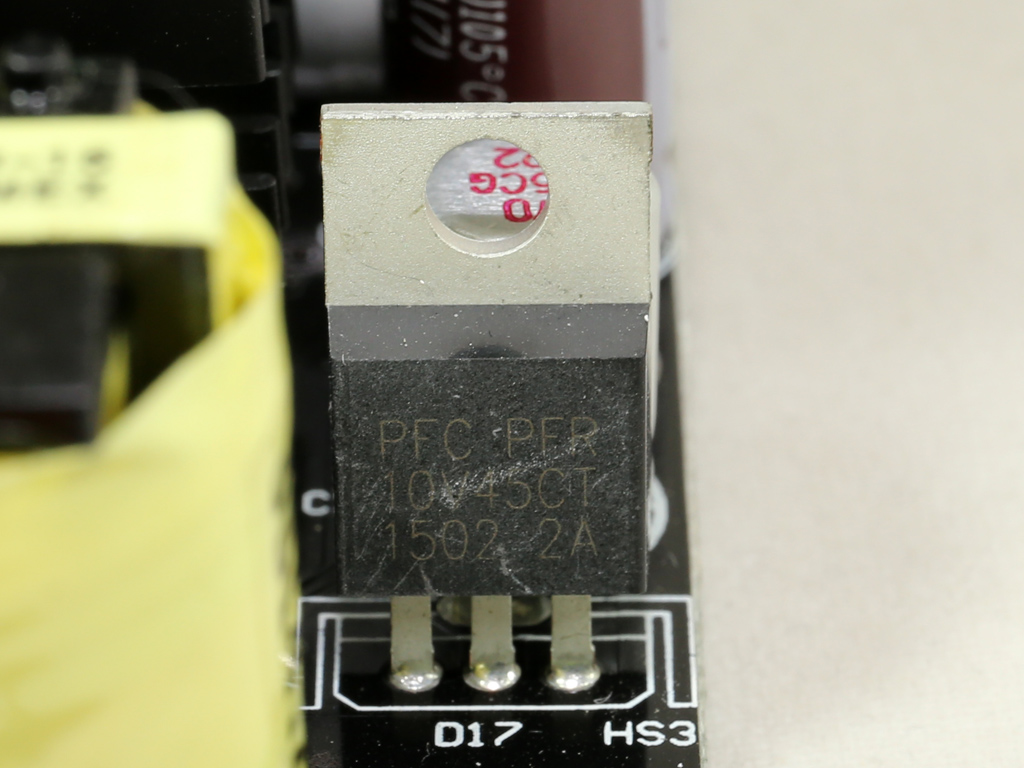
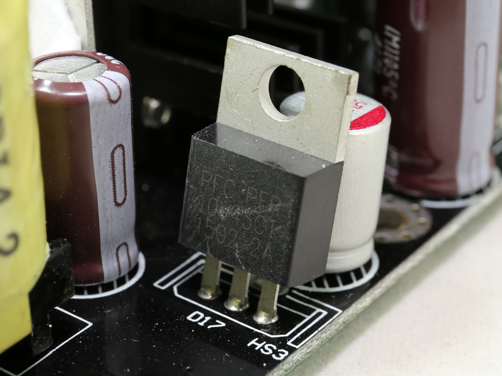
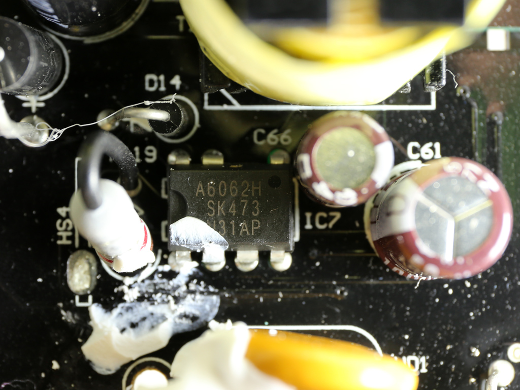
The 5VSB rail is regulated by a PFR10V45CT SBR, while the standby PWM controller is a Sanken STR-A6062H.
The -12V regulator is a L7912CV IC. Usually a simply diode handles this insignificant rail.
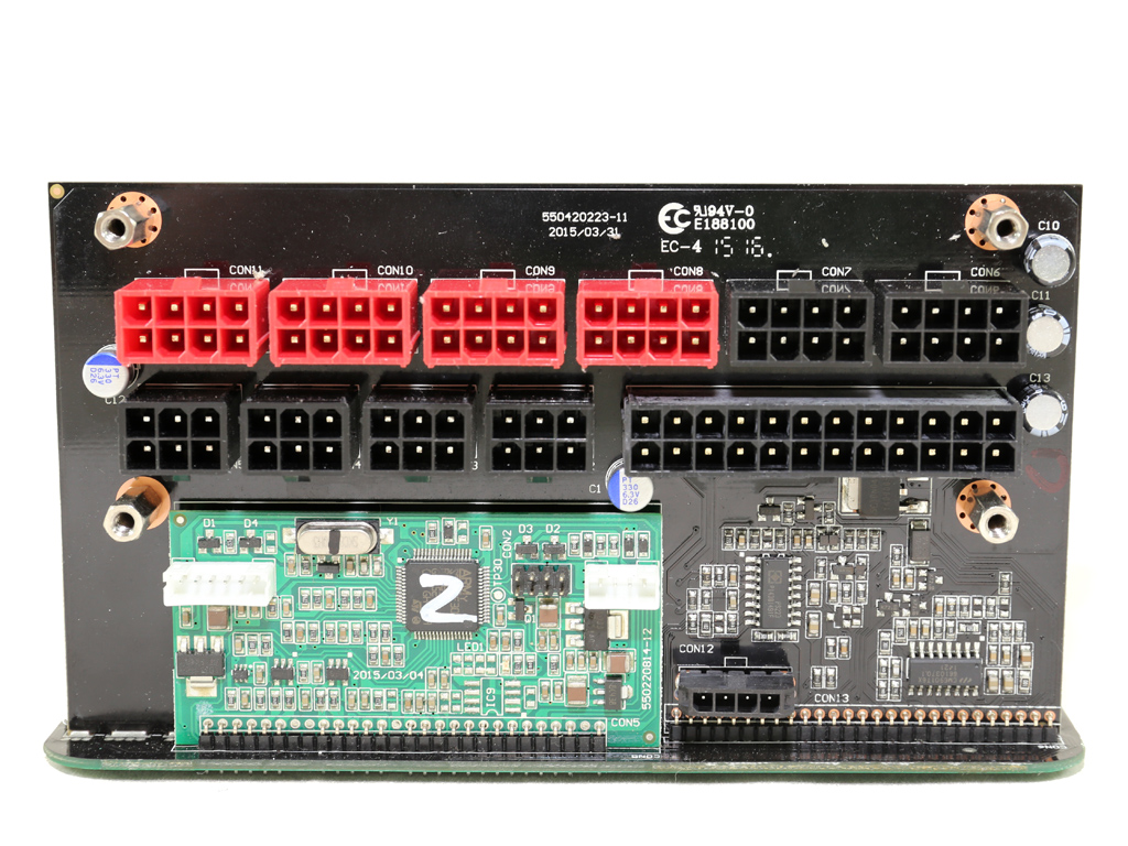
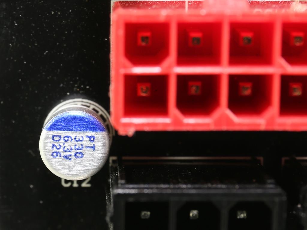
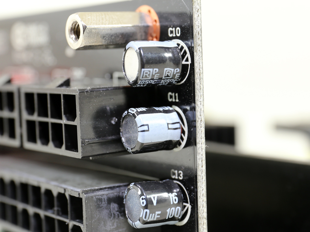
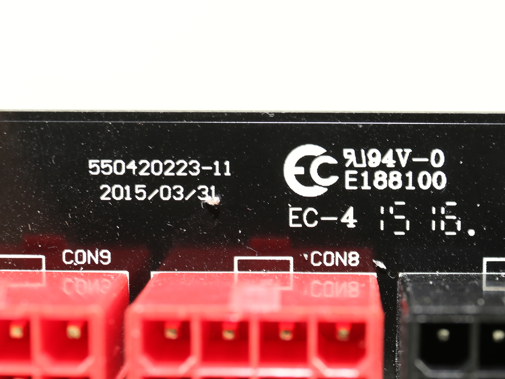
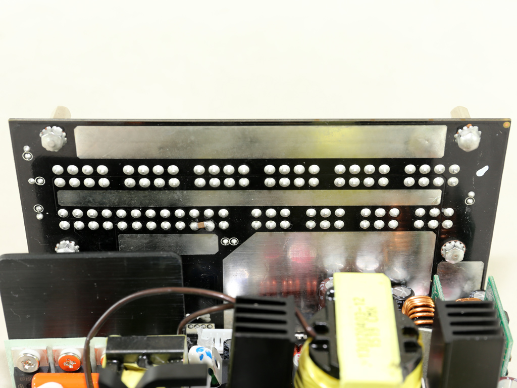
On the front of the modular board, a small number of polymer and electrolytic caps provide an extra ripple filtering layer.
The protections IC (a SITI PS223) and LLC resonant controller (a Champion CM6901) are hosted on the modular board. An SG30N04D FET is also installed there. Enhance usually uses this FET to feed the 5VSB rail from the 5V one.
In front of the modular PCB is a board responsible for exposing the digital link between Thermaltake's power supply and your motherboard. The MCU is provided by STMicroelectronics and its model number is STM32F302. This MCU includes a 32-bit ARM Cortex CPU operating at 72MHz. It includes 32KB of RAM and, besides a USB 2.0 interface, there is also a 12-bit DAC along with a temperature sensor that likely provides relevant info to the DPSApp. This MCU is also equipped with fast voltage comparators, op-amps, a 12-bit ADC and control timers. It operates with a voltage range of 2V to 3.6V, and when the PSU is in standby it is deactivated to minimize vampire power.
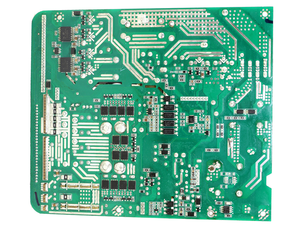
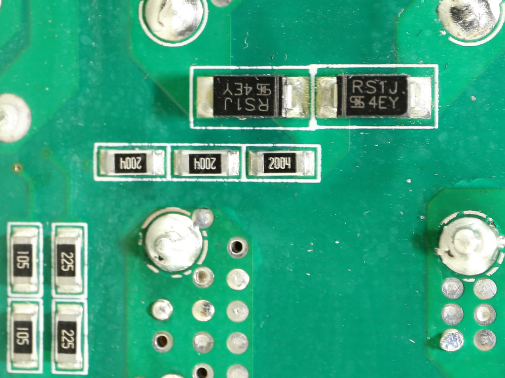
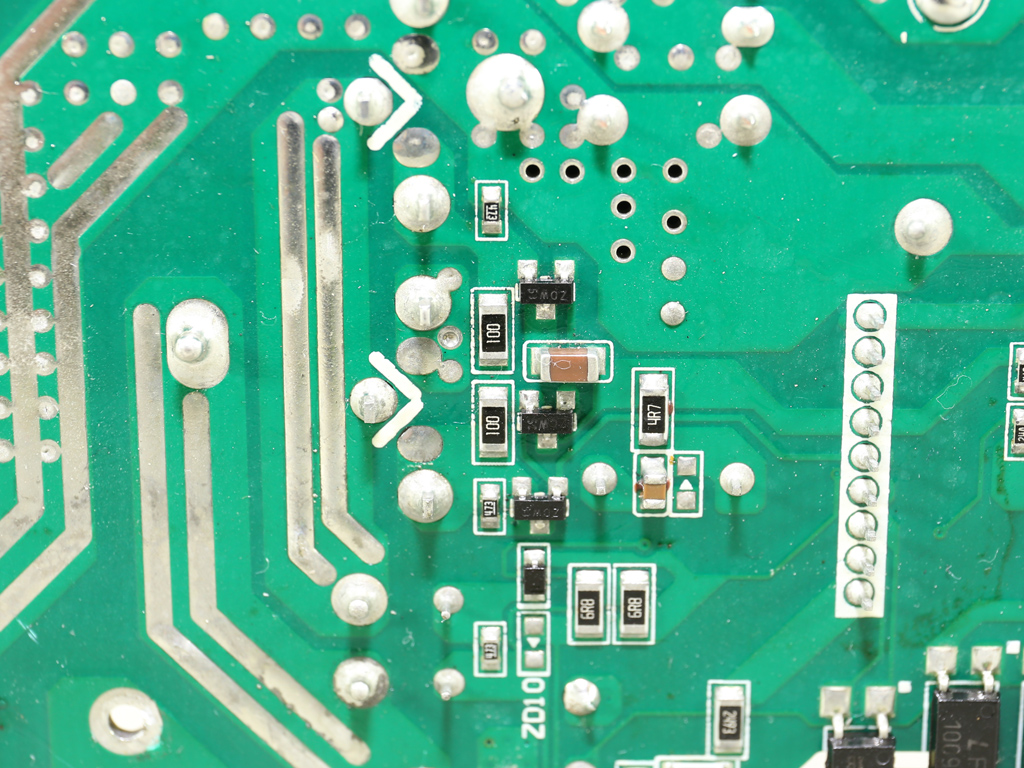
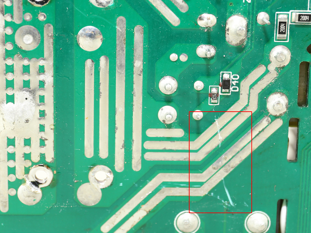
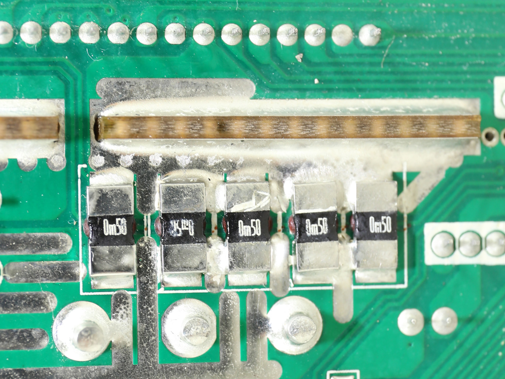
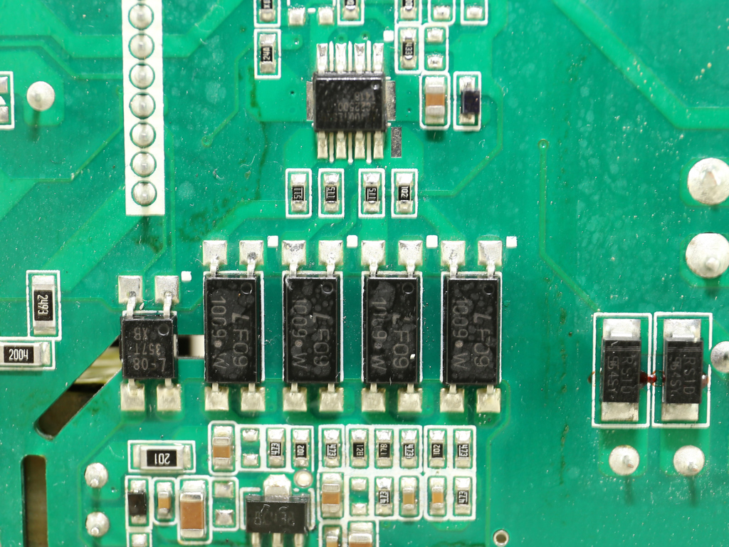
The soldering quality is great, as usually is the case for Enhance-made power supplies. We did, however, notice a small scratch on the PCB, though it shouldn't case any trouble.
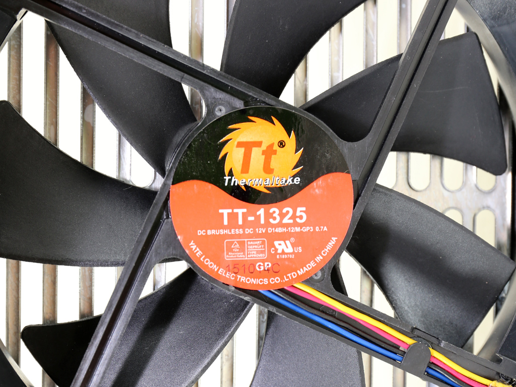
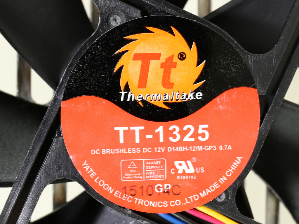
The cooling fan caries TT's logo, even though it's manufactured by Yate Loon (D14BH-12, 140mm, 12V, 0.70A, 2800RPM, 140 CFM, 48.5 dB[A]). Dual ball-bearings should translate to a long useful life, too.
In general, this is a powerful fan that does get noisy when it spins fast. Fortunately, Thermaltake uses a relaxed profile under low to moderate loads. Only when you push more than 800W does the PSU's acoustic output become noticeable.
Current page: A Look Inside And Component Analysis
Prev Page Smart Power Management And DPSApp Next Page Load Regulation, Hold-Up Time And Inrush Current
Aris Mpitziopoulos is a contributing editor at Tom's Hardware, covering PSUs.
-
Myrmidonas I do not see anywhere the limitation regarding the need of Flash Active X 15 and only that, in order the PSU's software DPSapp to operate. Is there anything changed? I own one of its little brothers the Toughpower 550W and on my system the DPSApp refuses to run on an Active X version higher than 15.In fact on the download page there is a note sayingReply
"※Note: The Adobe Flash Player ActiveX 20.0.0 version or above might NOT be compatible DPS G PC App."
http://www.thermaltake.com/dpsappdownload.aspx?type=dpsapp
or
"※Note: The DPS G PC App requires Adobe Flash Player Version 2.0.0.270 or above and Microsoft .NET Version 4.5 or above."
http://www.thermaltake.com/DPSGApp2download.aspx?type=dpsgapp2 -
TechyInAZ ReplyThis is a wimpy power supply. Bring on 5 KW units!
:lol: It would be great for litecoining machines. :) -
Aris_Mp hm I am not aware of this flash/directX issue. In my system I just installed the DPSApp and it ran fine. I have all updates installed. However this App still needs work and they should abandon the flash platform IMO.Reply -
Myrmidonas Reply18063833 said:hm I am not aware of this flash/directX issue. In my system I just installed the DPSApp and it ran fine. I have all updates installed. However this App still needs work and they should abandon the flash platform IMO.
In my case, I had no Flash on my system at all. I consider it dangerous and useless. But in order to operate DPSApp I first installed the latest version of Flash and the DPSApp crashes every time i try to open the GUI. Only on the v15 I manage to make it work. :sarcastic: -
TheUnhandledException ReplyPSUs in the >1kW range should deliver at least 3.5A-4A on 5VSB.
Why? It is the standby power? What modern system needs more than 15W standby? -
Aris_Mp it isn't the system that needs it, but the devices that you might try to charge through 5VSB when the PSU is in standby.Reply -
terroralpha so, there is absolutely no reason to buy this over the aging AX1200i or even the not-as-fancy HX1200i... in fact, if you buy this unit you either live in a country where corsair PSUs are hard to get or you are a moron.Reply
it failed the hold up requirement, regulation and ripple is mediocre at best, it's hideous and single rail designs really need to go from PSUs this powerful. 100 amperes is enough to arc weld! if the DSP malfunctions and send 100 amps down your motherboard or GPU, it'll set your house on fire. this isn't really a problem with old school analog designs. but with anything digitally controlled, bugs are always a concern.
AX1200i is a way better performer in pretty much every metric, has a 10 year warranty these days, and individually sleeved cables are relatively cheap and readily available.
