5 GHz Project: CPU Cooling With Liquid Nitrogen
The Same Still Applies: Selective CPU Buying
The standard P4 from 3 GHz (FSB800) is designed for a core voltage of 1.525 volts. The rule is that the signal quality within the CPU deteriorates as speed rises. By gradually increasing the voltage, the transistors’ switching behavior improves and higher clock rates are possible. That, however, means that some transistors are run outside of specifications with the result that their life expectancy sinks dramatically. In addition, raising the voltage increases power input and quadruples heat dissipation. The effect is immediate : the processor becomes extremely hot when running and needs powerful customized cooling.
In the lab, it was shown that a core voltage above 1,880 volts did not produce any stability gains.
Conclusion : 5.25 GHz - Liquid Nitrogen Cools The P4 To A New Speed Record
We set our sights pretty high for this test : the THG team set out to squeeze at least 5 GHz from the selected Intel P4. In the run-up we tested 10 different P4 CPUs for their overclocking potential. We also used a painstakingly modified Asus motherboard (P4C800-E) that featured a four-phase voltage regulator to allow for extreme voltages. The serial product only has a three-phase regulator. Nonetheless, almost 90 amperes are possible at top load, according to the VRM specs. When seriously overclocking the CPU, we recorded a current of 96 amperes, which even stretched the potential of the modified voltage regulator on the Asus P4C800-E.
Finally, by gradually increasing FSB speed from 200 MHz (factory setting) to 309 MHz, we achieved a record speed of 5255 MHz. The fixed multiplier caused problems on all of the P4 CPUs we examined. That meant that from the outset synchronous operation of FSB and memory speed was not an option. When all’s said and done, there is no DDR memory around that can be operated at 309 MHz. As a result of the 3:2 split (FSB to memory), we were able to reduce memory speed to 206 MHz. This meant Corsair’s two DDR550 modules had enough air - previously we recorded the maximum possible clock rate at 285 MHz (CL3 mode). As a point of comparison : synchronous operation at 285 MHz would result in a CPU clock rate of 4875 MHz - not enough for our needs by far. That said, we were also forced to recognize that memory performance in asynchronous mode sank by around 15 percent against synchronous operation. It just shows that you can’t rely just on the processor clock rate for getting the most out of your system.
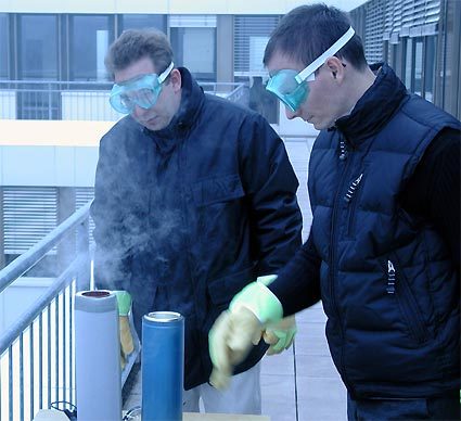
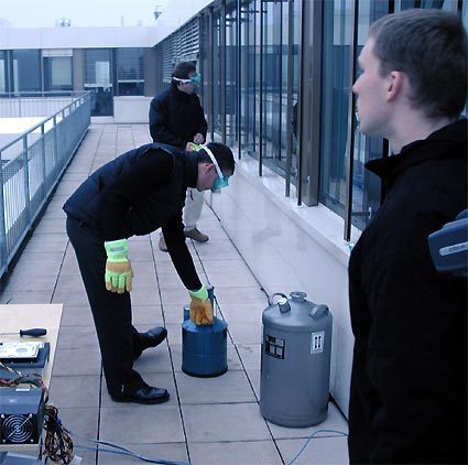
At full load, taking into account a maximum CPU heat dissipation of just under 175 watts, we recorded a temperature of approx. -190°C on the CPU cooling head. A record score that has yet to be beaten by any vaporizer system.
And another observation for fans of extreme overclocking : our test system was absolutely stable at a clock rate of 4700 MHz.
Get Tom's Hardware's best news and in-depth reviews, straight to your inbox.
Current page: The Same Still Applies: Selective CPU Buying
Prev Page Highspeed: FSB At 330 MHz, Memory At 285 MHz (DDR550)-
Now, with that big of a heatsink how do you plan to close the tower? How do you plan to renew the liquid nitrogen without blowing up your PCReply
-
you will notice that this was done outside... so not very safe I bet. Also you would never be able to keep switching the system on and off as the ice would damage the pcReply
-
NEOhm I couldn't help but think that there was a lot more they could have done to insulate the rest of the system from the CPU's immediate area .... I'm sure this system must have gone onto a crashing spree once all that ice built up and started short-circuiting all those electronics around the CPU's base .... for one example, they could have gone as far as to coating that area with silicone, i would think; or in the vary least, covering that area more to protect from the super cooled 'steam' flowing over the top of the copper tube and down onto the motherboard.Reply
Secondly, the over-use of thermal pastes ... from my understanding, application of thermal paste between a chip and a heatsink is supposed to be EXTREMELY THIN and evenly spread; any excess paste REDUCES thermal performance and just splotching it on can easily introduce air bubbles which would cause 'hot-spots' wherever a bubble lies.
If your going to draw attention to yourself by breaking some world records, it would be probably a good idea to do everything you can to make everything as perfect as can be ... for example, cleaning up the copper soldiering residues to 'good enough' levels isn't Good Enough!, go all the way and use scouring pads, polish and some attention to detail and people will respect you the more for your efforts and clean presentation. A key to success in life = Strive for excellence in whatever you do! Don't settle for second-best. -
Zorg I know it's late, but you guys are clowns.Reply
They did it and then took it apart and threw it in a box. Sorry it won't fit in a case and it wasn't shiny enough for you nitpickers.
Let me know how cool yours is when you get done.
If you're going to post garbage then don't post at all.

