The Math Behind GPU Power Consumption And PSUs
Power Consumption Measurement: Required Technology
With the graphics cards’ VR controllers switching back and forth so quickly, how much of this behavior is evident at the auxiliary power connectors? How difficult is it for the motherboard's slot and the PSU feeding those cables to keep pace?
First Steps With A Single Oscilloscope
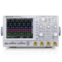
HAMEG HMO 3054
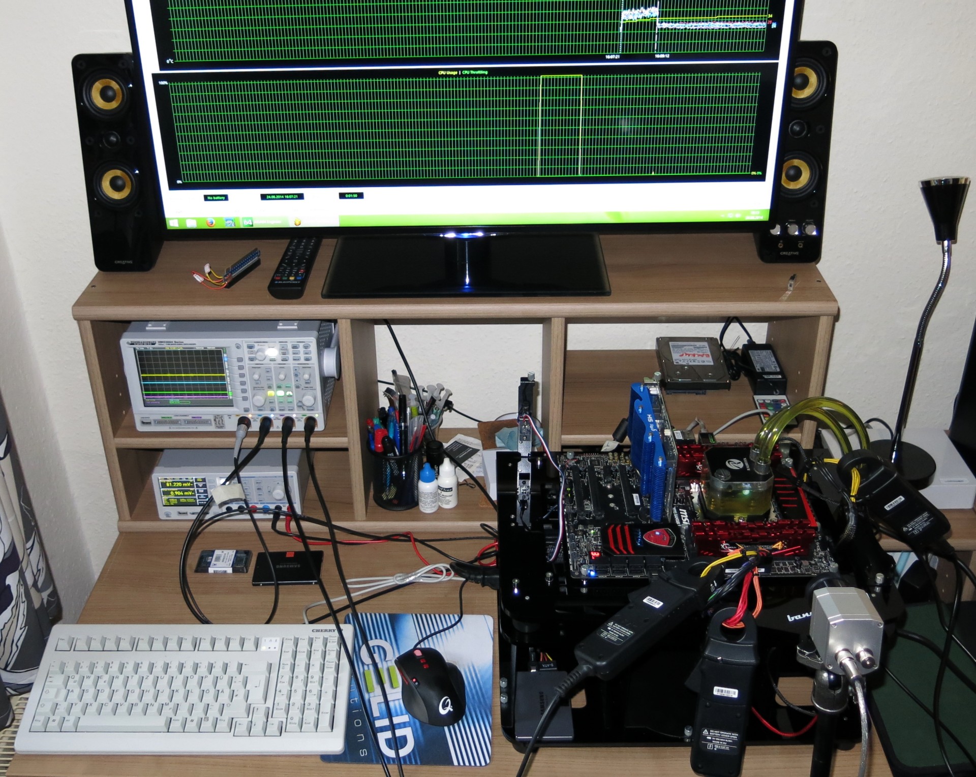
I planned the system around an emphasis on short measurement intervals. Unfortunately, this necessitated the use of a very good (and thus very expensive) oscilloscope with storage functionality. HAMEG’s HMO 3054 500MHz multi-channel oscilloscope served as the basis for my platform. It allows for the recording and storage of four channels, and has a helpful remote control via Ethernet.
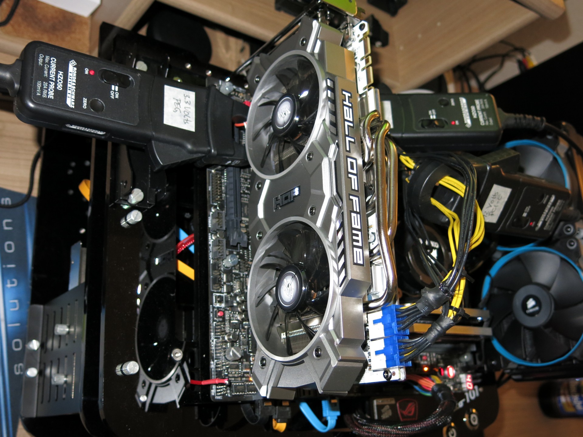
The next ingredient I added came in the form of several high-resolution HAMEG HZO50 current probes, which can be used for these frequencies without a problem and, more importantly, can be operated without range switching.
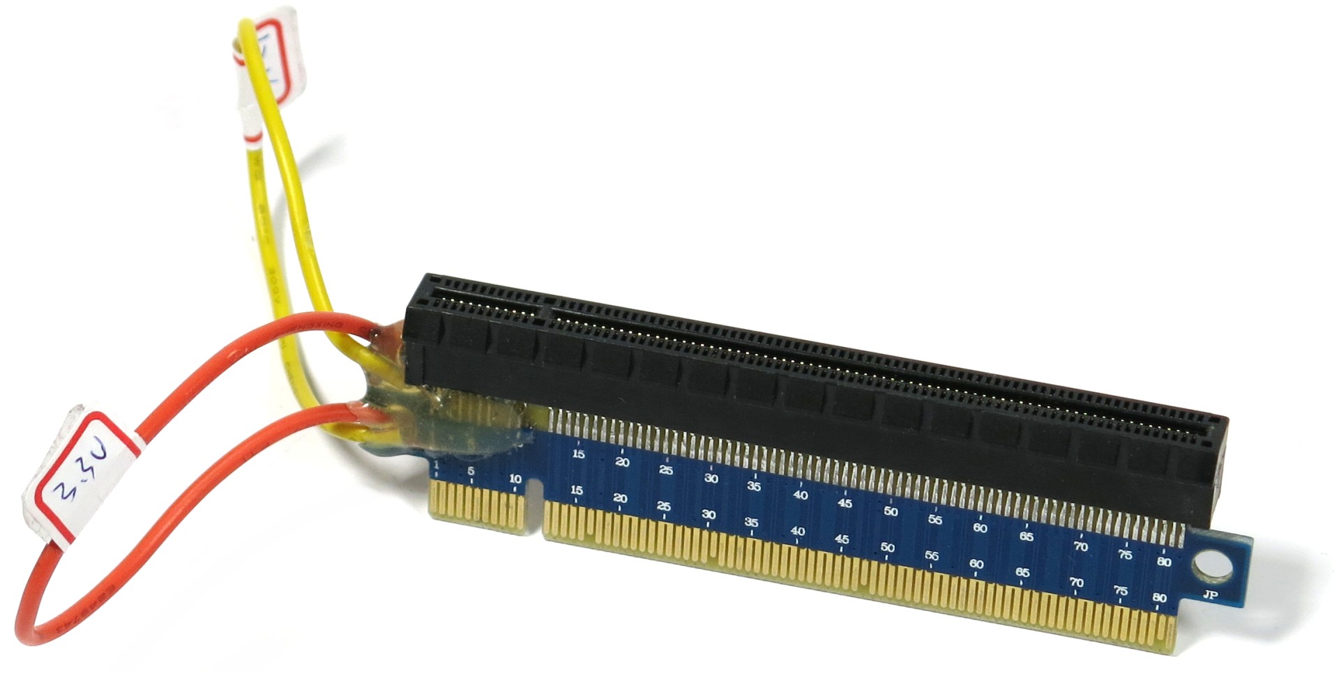
Another important tool is a special riser card with loops, which has to feature extremely short signal paths to be fully compatible with modern third-generation PCIe graphics cards. This adapter is inserted between the motherboard and the cards themselves.
Those who think that the measurements could be taken through two rails on a 24-pin ATX power connector, looped through to the graphics card slots, would be wrong. All of the motherboard’s power comes from the same pool, after all. This simply can't be achieved without the riser.
With our arts and crafts project completed, it was time for the strategic partnership with HAMEG (Rohde & Schwarz) to shine. The project just can’t be completed without laboratory-grade technology and the experience needed to use it.
The preliminary result of my efforts, which you've seen in our reviews over the past few months, was a heartening success. However, even though four channels seem to be more than enough, a closer analysis reveals that we need more.
Get Tom's Hardware's best news and in-depth reviews, straight to your inbox.
If the currents of both motherboard rails (3.3 and 12V) and the external PCIe power connector are measured, then all that’s left is one channel. It can be used to measure just one voltage. Since the PCIe connector sees the most action once the load goes up, I settled for taking that measurement and setting the voltages for the 3.3 and 12 V rails to those previously measured with a multimeter.
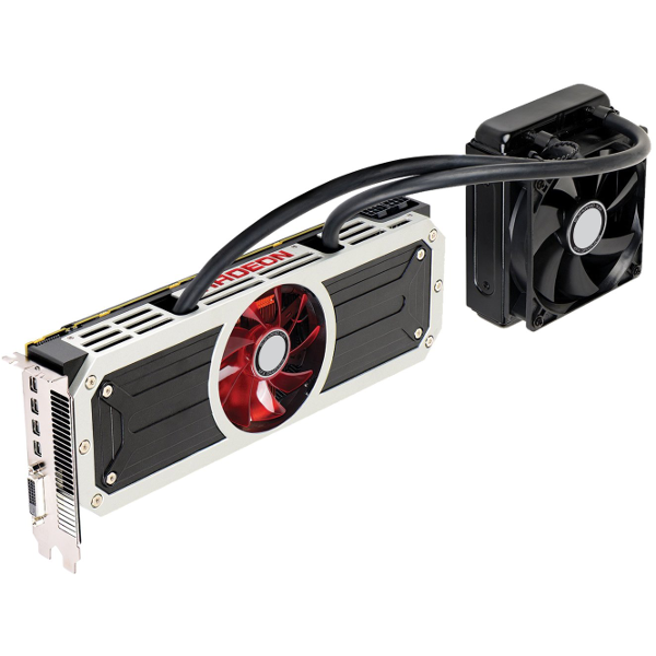
This approach reaches the limits of its usefulness once you get to graphics cards like AMD's Radeon R9 295X2. The PCIe connectors can’t be combined into one channel, since they serve different parts of the graphics card’s power supply. The currents can even flow the other way during short spikes, which I wasn't expecting to see.
Measuring with a single four-channel oscilloscope, three suitable current probe adapters and a probe might be in another league compared to measurements at the power outlet with a current clamp, or probes and multimeters. Unfortunately, it’s still not all that accurate. So what now?
Four-Point Measurements Times Two
Did I mention that this is an arms race of sorts? It sure feels that way if you’re trying to do this well! If the maximum four supply rails on a graphics card are supposed to be measured, then the oscilloscope needs to be able to handle a total of eight analog channels. After all, current and voltage need to be measured, and the results stored in parallel and in real time, at each of the four channels. Using previously measured values for the voltages can (and does) impact the results in a negative way, as we’ll see soon.
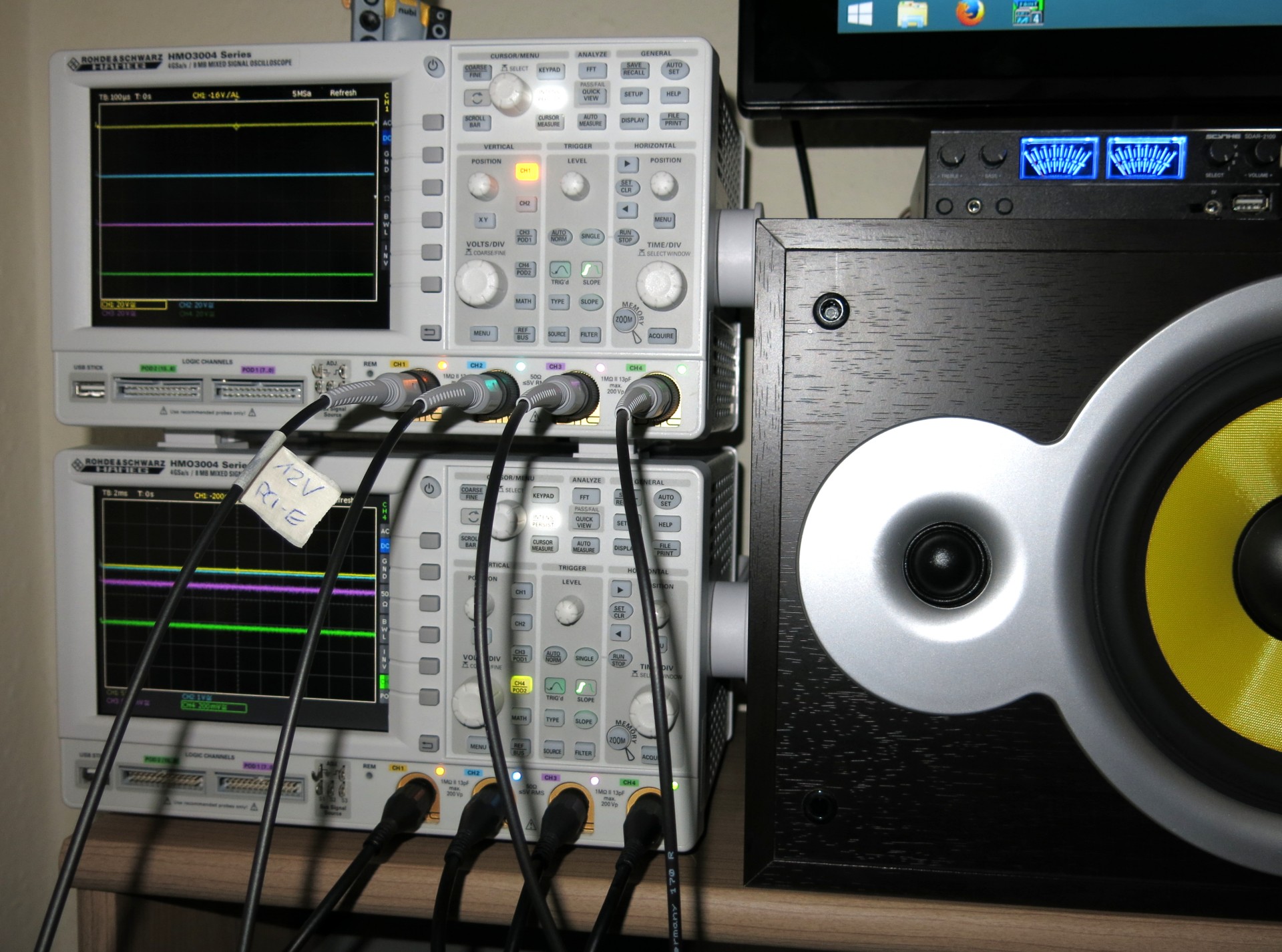
This is the point where I definitely had to make major changes to the measurement setup, and I once again enlisted our industry partner to help out. The solution consists of using two oscilloscopes in parallel (master/slave) to measure and record the data. The setup works perfectly at this point, allowing me to reliably measure a graphics card’s every last hiccup or sputter.
The bottom line is that we can measure currents and voltages down to a temporal resolution of a single microsecond. The interval needs to be adjusted depending on the application in question, because otherwise you might drown in the resulting massive amounts of data. For instance, if I conduct measurements for one-minute diagrams with a resolution of one millisecond, the oscilloscope averages the microsecond-resolution measurements for me.
We already talked about the measurement hardware in our previous foundation article. Here’s a quick overview of the most important information:
| Test Method | Contact-free DC measurement at PCIe slot (using a riser card)Contact-free DC Measurement at external auxiliary power supply cableDirect voltage measurement at power supplyReal-time infrared monitoring and recording |
|---|---|
| Test Equipment | 2 x HAMEG HMO 3054, 500MHz multi-channel oscilloscope with storage function4 x HAMEG HZO50 current probe (1mA - 30A, 100kHz, DC)4 x HAMEG HZ355 (10:1 probes, 500MHz)1 x HAMEG HMC8012 digital multimeter with storage function1 x Optris PI450 80Hz infrared camera and PI Connect |
| Test System | Intel Core i7-5960X at 4.2GHz and Raijintek Triton water cooler16GB G.Skill Ripjaws DDR4-2666 (4 x 4GB)MSI X99 Gaming 7 motherboard2 x Transcend SSD370 512GB (system, applications and data, storage)1200W be quiet! Dark Power ProMicrocool Banchetto 101 |
On the next page, we’ll get to what all of this looks like in detail and what conclusions can be drawn from it. The plot thickens, so read on!
Current page: Power Consumption Measurement: Required Technology
Prev Page Graphics Cards And Their Power Consumption Tricks Next Page Measuring Power Consumption: A Practical Implementation
Igor Wallossek wrote a wide variety of hardware articles for Tom's Hardware, with a strong focus on technical analysis and in-depth reviews. His contributions have spanned a broad spectrum of PC components, including GPUs, CPUs, workstations, and PC builds. His insightful articles provide readers with detailed knowledge to make informed decisions in the ever-evolving tech landscape
-
Vorador2 Man, everytime i'm truly fed up with Tom's posting news that read as press releases, and badly written opinionated pieces, a jewel of a deeply researched original article shows up.Reply
Thanks for reminding me of the reasons i started reading Tom's Hardware. -
FormatC It is always difficult to break down the complex content to find an understandable level for all. We may lose a lot of information by this way (and some experts and nitpickers will kill me) or write boring and extra dry stories for a handful of readers without simplifications. It is always hard for us to find a good compromise.Reply
This equipment, shown in the review, is a good basement for a lot of other in-dept reviews in Germany, like the efficiency analysis of Nvidias GeForce GTX 970. You simply need exact numbers to do this. :D
I've also visited PSU manufacturers in Asia this year and this VGA-PSU problem is now more in focus...
But all this are another stories and I hope, that we get for all this more translation capacity here in US/UK. If not: it is a good reason to learn German :D
-
gofasterstripes Tom's Hardware delivers another piece of technical journalism at the gold standard.Reply
Well done to all involved, thank you. -
s3anister This was an excellent read; thank you for the incredible amount of work done for this article.Reply -
justin2003jclc Hi Toms Hardware,Reply
Can you clarify on your rule number3 ? Do you means that most of the PC PSU in the market are linear power supply when you mention about analog? Do you mean that there is only minorities of PC PSU available in the market are using switching power supply design? -
This is GOLD! Kudos to Igor for writing such a superb article. I hope he makes all the PSUs he reviews, undergo the same tests. Can't wait for his PSU reviews :)Reply
-
pecul1ar Congratulations on finishing this year long experiment, and thank you for sharing us your findings. This must have lifted a load off your shoulders..Reply
Oh, so this was translated? Thank you for that as well :) -
NoShot So, my take away from this is my PC builder (will not name here but is one of the larger ones offering custom builds) mislead me on their configuration setups when they said a Corsair RM850 PSU would be fine for a r9 295x2 and a i7 4970k. Not surprisingly, I am having random issues with this build where the 29 295x2 would only activate one GPU after system reboot or awake from sleep mode. I was thinking it was a driver issue, but looks like I need to drop a couple hundred dollars on a replacement PSU.....great. Genuine thanks for the article though.Reply
