Re-assembling And Testing Your MediaSmart Server
When reassembling your MediaSmart Server, you have the advantage of going back to where you’ve already been, so things should be somewhat more familiar during this phase of operations. When you’re done, you’ll want to conduct some simple tests to make sure everything is as it should be and to check temperatures to make sure the system is working at least as well as it does out the factory door.
Step 1: Reinsert the Motherboard Tray
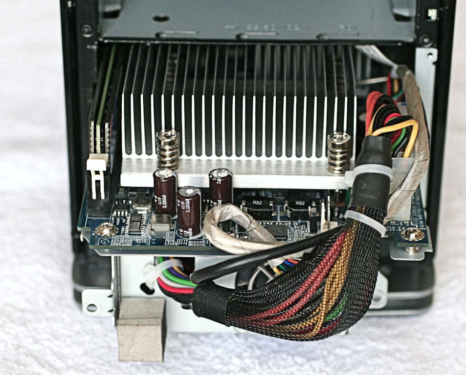
Slide the motherboard back into the case from the front. Here again, you may want to press down a little on the power supply cable bundle at the upper right to get the unit to slip in more easily. The tray should slide back in easily until the screw tabs on the tray exactly mate up to the screw holes in the case. Replace the two PC machine screws you removed to free the tray. Your magnetic screwdriver will come in handy when replacing the screw at the lower right, because it’s about 0.75" inside the case and hard to position with your fingers.
Step 2: Replace the Front Cage Cover
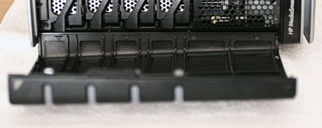
Lay the cover down in front of the case, with the bottom edge up against the bottom of the case, and reattach the status LED cable bundle at the lower right. Pick up the cage cover and insert the tabs at the left into their slots, then swing the cover to the right to line its screw holes up with the matching holes in the case. Now, it’s time to re-fasten those tiny machine screws. Grab your #0 Phillips head and carefully insert and tighten them down until just snug.
Step 4: Re-seat the SATA Backplane Board and Re-attach the Cables
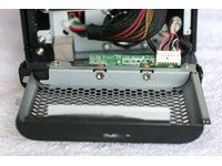
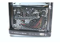
First, drop the backplane board into the slot at the rear of the case, then position the card so that it slides over the four retaining tabs (two each at the right and left sides). Reach inside the case from the front and position the board so that it fits onto the modular connector on the motherboard (a little back and forth will help you find the right position). Then you simply push down on the card until it seats itself.
Get Tom's Hardware's best news and in-depth reviews, straight to your inbox.
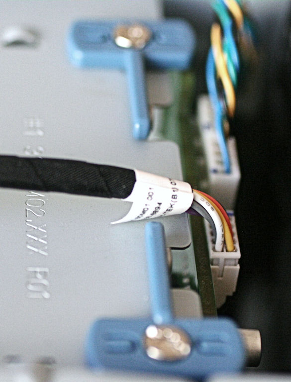
After that, you must replace the fan cables into their respective slots (this is where my R and L markings come in handy, though they refer to the perspective from the rear of the unit) and the sensor/LED cable bundle into the 10-pin connector housing. Finally, swing the left and right locking latches back into the locked position.
Step 5: Replace the Drive Trays
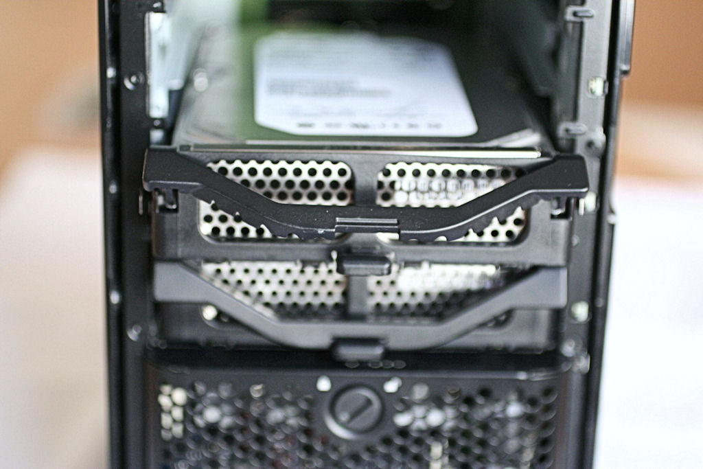
Working from the bottom up, replace the drives into the unit from the top down. That is, take the top drive from your stack and put it into the bottom slot in the MediaSmart Server. Take the next drive and put it into the slot above it and repeat until all the drive trays have been replaced. Because the drive trays feel somewhat flimsy, I tend to reach inside the case, lay my fingers down on top of the drive, and push from there to establish a firm seat for each one’s power and data SATA connectors. When it comes to the last drive, I insert a narrow tipped screwdriver through the tray grill onto the drive housing itself and push from there. This provides much more positive traction. When the drives seat properly, the front latch also closes automatically as well (you can, however, force it closed even if the drive isn’t seated, which is why I recommend the various techniques to make sure that happens).
Step 6: Replace the Top Deck and Front Door
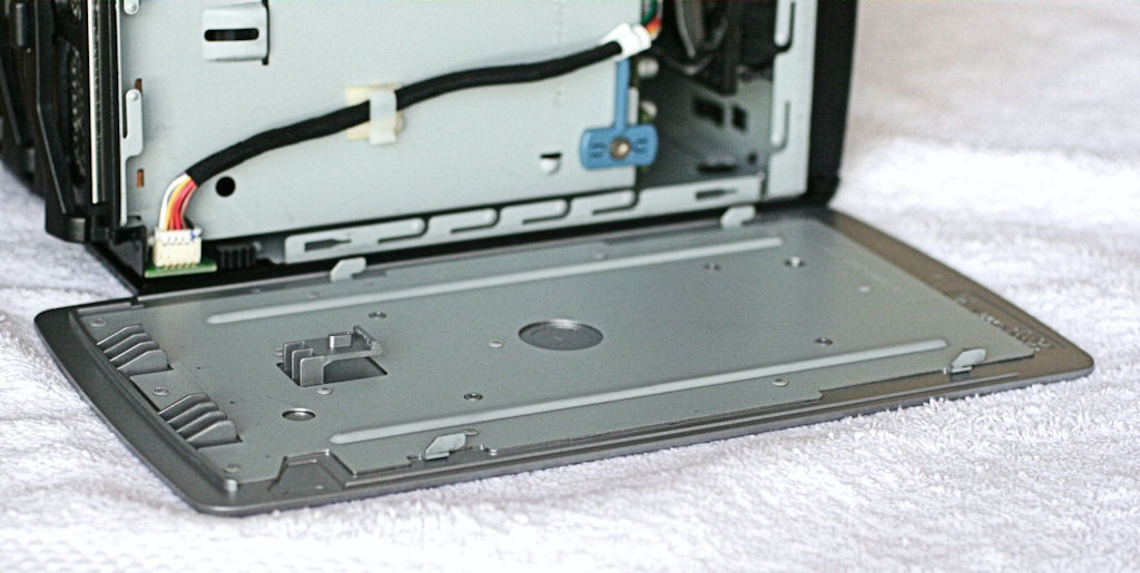
Position the top deck so that the four metal guides on its underside match up with the corresponding slots on the case top. As the photo shows, these are slightly offset on the left and right sides so you can only put the top on one way (properly, that is). After you position the top inside the guide, push the front edge toward the back of the case until it locks into position. This is much easier than loosening the top prior to removal.
The last step is to replace the front door. Please make sure all drive trays—especially empty ones—have been completely inserted into their bays or the door won’t close all the way. Fit the bottom plastic pivot from the door into the hole in the lower latch, then press down slightly on the top of the door, and pop the top pivot into its latch hole. The door should swing shut easily, and latch with just a little more pressure.
Congratulations! You’ve modified your HP EX47* MediaSmart Server. Before you can declare victory and move onto something else, you must still check your work. You’ll want to pass all of these post-upgrade checks to make sure things are working as they should.
Step 7: Post-upgrade Checks
Install the following software items on your MediaSmart Server:
- Grab HWMonitor and CPU-Z from CPUID.com. As I write this article, the current versions are 1.13 (HWMonitor) and 1.50 (CPU-Z).
- Create a directory called CPU-Z on your C: drive, then unzip the contents of the two download ZIP files into that directory.
- Run CPU-Z and check your CPU and memory status. If you did the BIOS hack and a CPU upgrade, the proper CPU should be reported. If you only upgraded the memory, you should see 2048 Mbytes reported on the Memory tab.
Run HWMonitor and check your temperature readings. If you applied thermal paste to the northbridge heatsink, you should see readings of 55 degrees Celsius or less for TMPIN0. You should also see readings of 45 degrees Celsius or less for TMPIN1 (CPU socket) and 38 degrees Celsius or less from TMPIN2 (CPU temperature sensor). For dual-core CPUs, don’t be surprised to see “silly numbers” (under 20 degrees Celsius).
It’s not unusual for multi-core CPU readings to be incorrectly reported in the MediaSmart Server. You can always make a sanity check on TMPIN2 by opening the Windows Home Server Console, then checking the Hardware values in Settings. Watch your upgraded server carefully over the next 24 to 48 hours and check the Event Viewer for errors, especially for unexpected shutdowns. Keep an eye on your temps as well (if you leave HWMonitor running, it will show you the temperature history for your machine during the most recent uptime interval).
Check prices for HP's MediaSmart EX475
Current page: Re-assembling And Testing Your MediaSmart Server
Prev Page How To Prepare And What To Do If Something Goes Wrong Next Page A Little Cash, A Little Elbow Grease, And A Little TimeEd Tittel is a long-time IT writer, researcher and consultant, and occasional contributor to Tom’s Hardware. A Windows Insider MVP since 2018, he likes to cover OS-related driver, troubleshooting, and security topics.
-
neiroatopelcc Seems like a nice do-it-yourself guide. I don't own such a nas, so I can't tell if something's missing. But it's nice to see something like this on toms. Too rarely do we get such a treat.Reply
Now tell us how we can convert a zyxel router into a storage system, or how we can mod a sata controller into a sas controller, or whatever else can be done to hardware if you know how.
ps. it's a bit wierd that you describe how to unplug an atx power cable ... I would expect people who'd dare take their working nas apart would know, or figure that out, on their own. -
DiscoDuck Has anyone run performance numbers on single versus dual core on a homebrew WHS? IS it possible the small gains on the HP dual core setup are a limitation of the motherboard?Reply -
FrustratedRhino It is a computer... no matter how evil it is inside, since the compaqs of the late 80s/early 90s every computers is very easy to upgrade. To say that a HTPC knockoff needed a whole guide, to upgrade it, is rather silly.Reply
Slow news day I guess. -
deredita Excellent write-up. I been thinking about the HP MediaSmart servers, and what would be involved to mod one.Reply -
etittel DiscoDuckHas anyone run performance numbers on single versus dual core on a homebrew WHS? IS it possible the small gains on the HP dual core setup are a limitation of the motherboard?Reply
Good Question! I didn't think to tackle this within the scope of the current story, but it certainly would make fertile ground for a look at WHS in general. Having built numerous (more than 20) AMD AM2 systems and benchmarked them all, I didn't get the sense that we were dealing with motherboard limitations. Tim Higgins at SmallNetBuilder gives the EX470/475 models pretty high marks in head-to-head comparisons with other NASes so I don't think this box is hampered by inherent performance problems. But comparing it to other builds/set-ups is a good idea, and I will see if my editor is interested in a follow-up.
Thanks!
--Ed--
PS to neiroatopelcc: I wish I knew how to convert a zyxel router into a NAS/SAN, or how to mode SATA into SAS controllers. Both are things I too would like to know how to do. -
MoUsE-WiZ FrustratedRhinoIt is a computer... no matter how evil it is inside, since the compaqs of the late 80s/early 90s every computers is very easy to upgrade. To say that a HTPC knockoff needed a whole guide, to upgrade it, is rather silly.Slow news day I guess.Yeah, that. Glancing through the guide, anybody who's ever done any sort of hardware upgrade on any machine should be able to figure all of this out, changing the BIOS is probably the only bit that requires any extra knowledge.Reply
Next up; guide to fitting square peg in square hole? -
etittel To all:Reply
I'd like to thank HP and Micron/Crucial for their support of this article. Micron actually overnighted me a 4GB DDR2-667 SDRAM module when I was unable to buy one anywhere in the US, on very short notice.
I'd also like to thank the following terrific HP MediaSmart sites that helped me learn what I needed to know to write this story:
1. Alex Kuretz: www.mediasmartserver.net
2. Capable Networks MediaSmart Home (May be MS sponsored, hard to tell, still useful tho)
3. Terry Walsh We Got Served4. Andrew Edney Using Windows Home Server5. Donavon West Home Server Hacks6. Microsoft WHS Team Homeserver Blog
There may be more, but these are the most useful such sites I found. If you know of any please add them here.
--Ed-- -
etittel Drivers for EX47* ServersReply
I recently blogged on my own Vista site to list all of the latest workable drivers for the EX470/EX475 MediaSmart Servers. Anybody interested in making sure they're current on drivers should find this useful. I include the link to download.com for some less-than-brand-new drivers (which SiS has since updated, but which don't work on the EX47* models) because SiS doesn't keep an archive of older drivers (at least, not where I could find them).
HTH,
--Ed-- -
etittel Sorry forgot the driver link URL: http://viztaview.wordpress.com/2009/03/05/drivers-for-hp-ex-47-mediasmart-servers/. My apologies.Reply
--Ed-- -
cruiseoveride So basically, you buy an over priced media center "PC" and then upgrade it?Reply
okaaaaay
