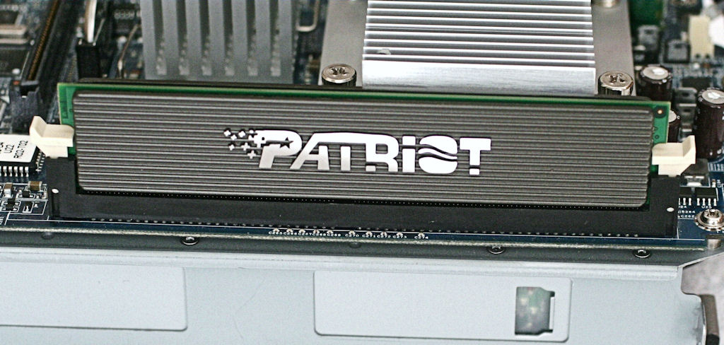
Memory Upgrade
When it comes to performing a memory upgrade, the obvious options are to go from 512 MB to either 1.0 GB or 2.0 GB. But because HP’s new units include 2.0 GB, I skipped 1.0 GB entirely, and instead benchmarked the upgraded systems following a 2.0 GB and a much more costly 4.0 GB upgrade. Because you can buy a 2.0 GB module of the right kind for about $20-$30 and all 4.0 GB modules cost over $100—when you can find them—any cost/benefit analysis of the benchmark results comes down heavily in favor of the cheaper, lower-capacity 2.0 GB module. I had to ask for help from Micron/Crucial to lay hands on a $150 module it offers, which had to be shipped to the United States from Scotland because it wasn't available in the United States.
Next, let’s take an HP EX475 apart so you can access the memory socket to remove the 512 MB module and replace it with its 2.0 GB counterpart. Each step along the way is illustrated with a photo. Here’s a list of tools you’ll want to have on hand (and purchase, if necessary):
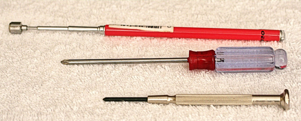
- Small Magnetic tip Phillips screwdriver (or telescoping magnetic pick-up tool, readily available at car-parts stores for $3-$4).
- #0 Precision Phillips Screwdriver (if you can’t find one locally, here’s a modestly-priced $4.65 model from Electronic City). I used the smallest Phillips screwdriver from a cheap set of hardened steel jeweler’s tools I purchased at Fry’s for $5.
- (Optional) pair of small needlenose pliers (useful for slipping modular connectors out of their receptacles when a finger grip isn’t good enough to do the job).
Step 1: Remove Front Door and Top Panel Cover from Unit
I usually place the unit on top of a towel when working on a desktop or other furniture surface. While the EX47* and EX48* have nice black rubber feet underneath them, these might mark up light-colored or polished surfaces without some kind of protective layer beneath the unit.
To remove the door, swing it open. A small plastic pivot point on the upper hinge is all that holds the door onto the case. Push down on the door with your right thumb near the hinge, and it should pop out and swing away from the case. Lift the bottom pivot point out of its holder, and the door is off. Please be gentle throughout this process. HP did a great job of engineering this hardware but it hasn’t been built for constant tinkering as a stock PC usually is.
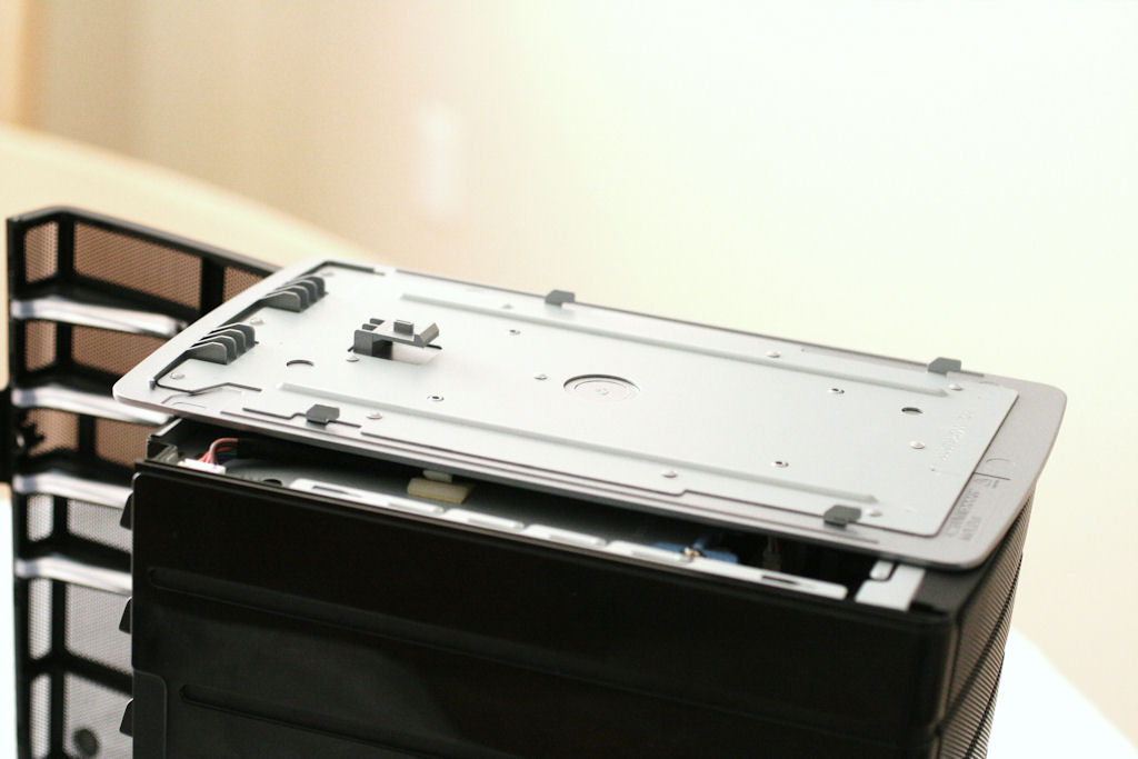
To remove the top panel, which is made of sturdy silver plastic with a sheet metal inside liner, grab the front edge firmly with your right hand, and push from the back with your left hand. The panel is held in place by four steel clips, which you must slide forward about 0.5" to release. This will take a bit of force to accomplish, and is the only time you’ll use any real muscle in working with this unit (reassembly is much easier and takes far less effort). If you push down a little with your left hand while also pushing forward and pull with the fingers of your right hand, you’ll find this helps to loosen the top from its usual anchor points.
Step 2: Remove the Drive Trays (and Drives)
Get Tom's Hardware's best news and in-depth reviews, straight to your inbox.
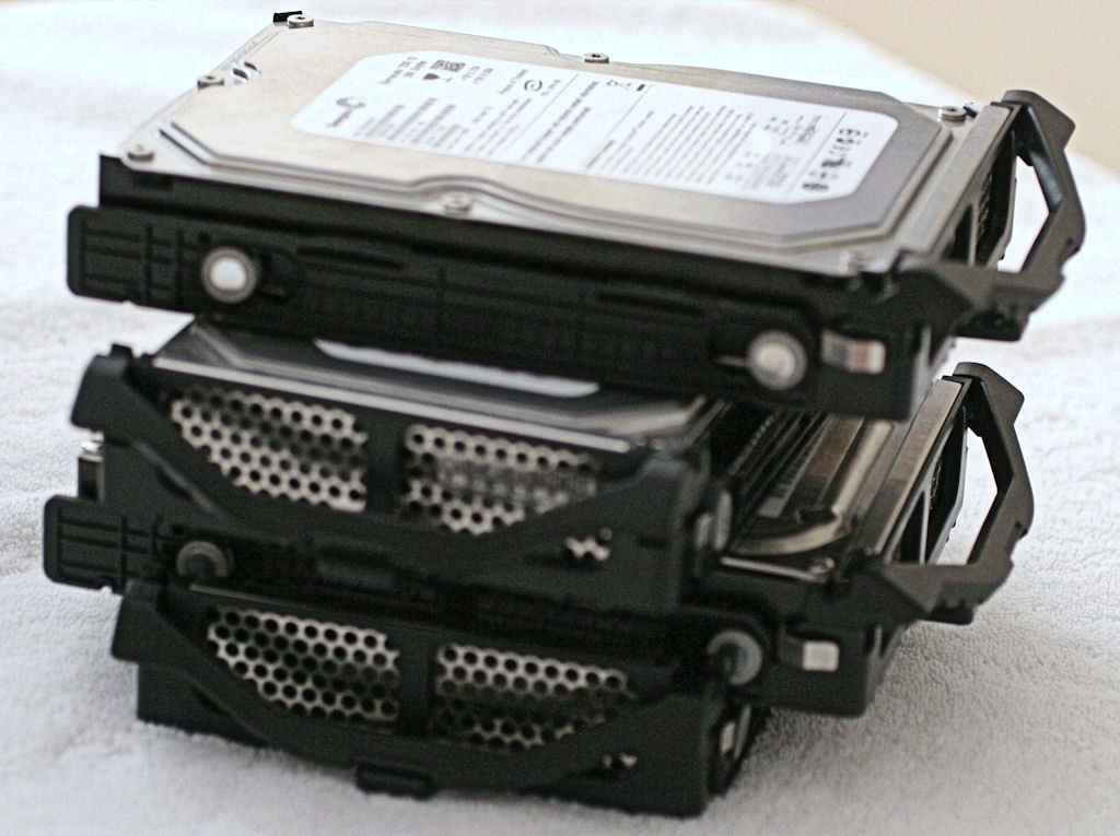
The HP MediaSmart Server cares a great deal about physical drive arrangement and order. When you take the drive trays out of the unit, remove the top one first. Lift the latch at the center of the tray, then pull gently on the A-arm at the bottom of the tray. Once you get the first tray out, if you encounter resistance in removing other trays, you can reach inside the enclosure and grab the rear edge of the drive for a gentle pull forward. I worried about the plastic trays being too flimsy, and got into this habit pretty quickly. As you remove each tray from the top town, stack it on top of the preceding trays (I rotate mine 90° between layers, to make the stack more stable). When you finish, the bottom (system) drive should be on top of the stack.
Step 3: Loosen the Backplane Cables and Unlock the Latches
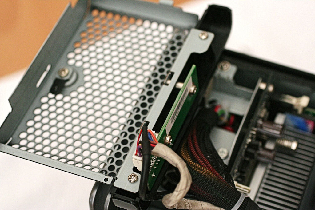
As shown in the initial photos, a pair of (four-pin) fan cables in black, yellow, and blue and a 10-pin control cable connector plug into the top of the SATA backplane at the rear of the enclosure. You’ll want to gently remove the fan cables and the 10-pin connector from their mountings. It’s pretty safe to grab these cables by the connector or the wires just as they enter the connector and gently remove them from their mounts. The fan cables should slide right out (I marked mine L and R for left and right to make sure they went back into the right pin blocks). You may have to gently rock the 10-pin connector side to side to get it to let go.
Finally, you’ll want to swing the two latches down that lock the SATA card into place. From the front, the left-hand side latch swings left, and the right-hand side latch swings right. Swing both 90° so that the handles are parallel to the sides of the case.
Step 4: Remove the Backplane from the Motherboard
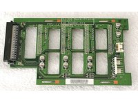
The green circuit card with an edge that is flush with the back opening in the case is a modular four-port SATA backplane that plugs into a special socket in the motherboard below. It’s where each of the four internal SATA drives that the HP MediaSmart Servers accommodate plug in for motherboard access. You must lift this card up to undock it from the motherboard. The easiest way to do this is to reach inside the drive bays, then stick one or two fingers through one or two of the holes in that circuit board. If you gently lift the card just a little in this way, it should lift free from the motherboard. It’s attached to the drive cage on four metal guides, two along each side edge. To remove the card from the case, slide the card up gently until the metal guides line up with the slots in the card itself. Then you can easily remove the card from the case without difficulty.
Step 5: Remove the Front Cage Cover
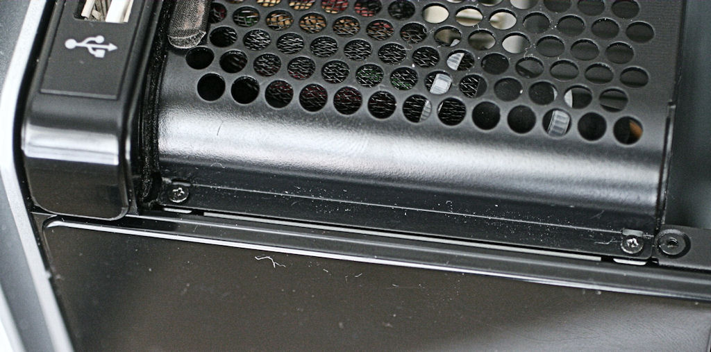
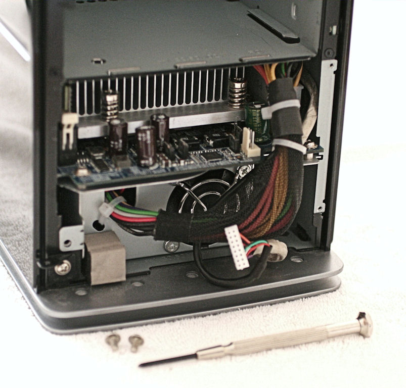
This is where a small, precision, hardened tip screwdriver is absolutely essential. Two miniscule machine screws hold this cover in place at the top and bottom right as shown in the photo. You must be careful when loosening or tightening these screws because they are small enough to be extraordinarily susceptible to damage (stripped threads or chewed out crosspoints).
That’s why I and other MediaSmart hackers recommend spending a few dollars to purchase the right kind of screwdriver for this task. Once the screws are removed, rotate the cage cover to the left, and you can slip it free from the latching metal tabs on the left edge to detach the cage. Finally, you must remove the modular connector that powers the status LEDs for this device to free the cage completely. You can now see the motherboard at the bottom of the case, ready to be removed.
Step 6: Remove the Motherboard Tray
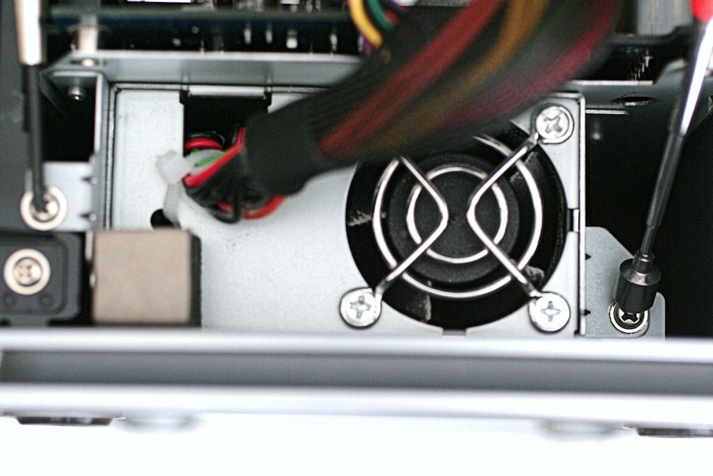
The motherboard tray is secured by two normal-sized PC machine screws at the lower left and inside on the lower right. Make sure to identify the screws that attach to the white metal motherboard tray (other screws are nearby, but loosening them won’t free the motherboard). Remove these screws and you’re ready to slide the motherboard out. In the photo, I’ve positioned a screwdriver on one screw and the magnetic grabber on the other, which are your targets.
Notice the power supply cable at the upper right. You may need to push this down slightly to enable the motherboard to slide forward. Please be gentle: there are lots of soldered parts (three big capacitors at front left for example) that you should try to leave untouched if at all possible.
Step 7: Switch the Memory Module
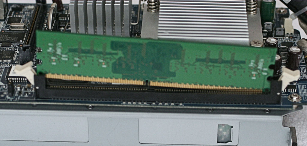
With the motherboard tray out, it’s absurdly easy to switch the memory modules. Loosen the clips to the right and left of the module holder, then remove the old 512 MB module. Slide the new module into the holder (and make sure the center divider lines up properly so the module will seat correctly), then push the clips on each side to lock the module into place.
Congratulations! You’ve finished the first task! Before we go on to the second task, let’s take a look at some benchmark results from the EX475 with 0.5, 2.0, and 4.0 GB of RAM and the stock Sempron 3400+ CPU.
Check prices for HP's MediaSmart EX475
Current page: Memory Upgrade
Prev Page Task List For DIY EX47* Upgrade Next Page Benchmarking Standard And Increased Memory ConfigurationsEd Tittel is a long-time IT writer, researcher and consultant, and occasional contributor to Tom’s Hardware. A Windows Insider MVP since 2018, he likes to cover OS-related driver, troubleshooting, and security topics.
-
neiroatopelcc Seems like a nice do-it-yourself guide. I don't own such a nas, so I can't tell if something's missing. But it's nice to see something like this on toms. Too rarely do we get such a treat.Reply
Now tell us how we can convert a zyxel router into a storage system, or how we can mod a sata controller into a sas controller, or whatever else can be done to hardware if you know how.
ps. it's a bit wierd that you describe how to unplug an atx power cable ... I would expect people who'd dare take their working nas apart would know, or figure that out, on their own. -
DiscoDuck Has anyone run performance numbers on single versus dual core on a homebrew WHS? IS it possible the small gains on the HP dual core setup are a limitation of the motherboard?Reply -
FrustratedRhino It is a computer... no matter how evil it is inside, since the compaqs of the late 80s/early 90s every computers is very easy to upgrade. To say that a HTPC knockoff needed a whole guide, to upgrade it, is rather silly.Reply
Slow news day I guess. -
deredita Excellent write-up. I been thinking about the HP MediaSmart servers, and what would be involved to mod one.Reply -
etittel DiscoDuckHas anyone run performance numbers on single versus dual core on a homebrew WHS? IS it possible the small gains on the HP dual core setup are a limitation of the motherboard?Reply
Good Question! I didn't think to tackle this within the scope of the current story, but it certainly would make fertile ground for a look at WHS in general. Having built numerous (more than 20) AMD AM2 systems and benchmarked them all, I didn't get the sense that we were dealing with motherboard limitations. Tim Higgins at SmallNetBuilder gives the EX470/475 models pretty high marks in head-to-head comparisons with other NASes so I don't think this box is hampered by inherent performance problems. But comparing it to other builds/set-ups is a good idea, and I will see if my editor is interested in a follow-up.
Thanks!
--Ed--
PS to neiroatopelcc: I wish I knew how to convert a zyxel router into a NAS/SAN, or how to mode SATA into SAS controllers. Both are things I too would like to know how to do. -
MoUsE-WiZ FrustratedRhinoIt is a computer... no matter how evil it is inside, since the compaqs of the late 80s/early 90s every computers is very easy to upgrade. To say that a HTPC knockoff needed a whole guide, to upgrade it, is rather silly.Slow news day I guess.Yeah, that. Glancing through the guide, anybody who's ever done any sort of hardware upgrade on any machine should be able to figure all of this out, changing the BIOS is probably the only bit that requires any extra knowledge.Reply
Next up; guide to fitting square peg in square hole? -
etittel To all:Reply
I'd like to thank HP and Micron/Crucial for their support of this article. Micron actually overnighted me a 4GB DDR2-667 SDRAM module when I was unable to buy one anywhere in the US, on very short notice.
I'd also like to thank the following terrific HP MediaSmart sites that helped me learn what I needed to know to write this story:
1. Alex Kuretz: www.mediasmartserver.net
2. Capable Networks MediaSmart Home (May be MS sponsored, hard to tell, still useful tho)
3. Terry Walsh We Got Served4. Andrew Edney Using Windows Home Server5. Donavon West Home Server Hacks6. Microsoft WHS Team Homeserver Blog
There may be more, but these are the most useful such sites I found. If you know of any please add them here.
--Ed-- -
etittel Drivers for EX47* ServersReply
I recently blogged on my own Vista site to list all of the latest workable drivers for the EX470/EX475 MediaSmart Servers. Anybody interested in making sure they're current on drivers should find this useful. I include the link to download.com for some less-than-brand-new drivers (which SiS has since updated, but which don't work on the EX47* models) because SiS doesn't keep an archive of older drivers (at least, not where I could find them).
HTH,
--Ed-- -
etittel Sorry forgot the driver link URL: http://viztaview.wordpress.com/2009/03/05/drivers-for-hp-ex-47-mediasmart-servers/. My apologies.Reply
--Ed-- -
cruiseoveride So basically, you buy an over priced media center "PC" and then upgrade it?Reply
okaaaaay
