SilverStone SX550 SFX PSU Review
SilverStone continues to enrich its SFX PSU portfolio. One of the most recent additions is the SX550, a budget-oriented unit featuring Gold-class efficiency and fixed cables instead of modular ones. As you can tell, it's intended to bring prices down.
Why you can trust Tom's Hardware
A Look Inside And Component Analysis
Parts Description
Before proceeding with this page, we strongly encourage you to a look at our PSUs 101 article, which provides valuable information about PSUs and their operation, allowing you to better understand the components we're about to discuss. Our main tools for disassembling PSUs are a Thermaltronics soldering and rework station, and a Hakko FR-300 desoldering gun.
| Primary Side | |
|---|---|
| Transient Filter | 4x Y caps, 3x X caps, 2x CM chokes, 1x MOV |
| Inrush Protection | NTC Thermistor & Relay |
| Bridge Rectifier(s) | 2x GBU10V06 (600 V, 2.9 A @ 100 °C - without heat sink) |
| APFC MOSFETs | 2x Infineon IPA60R125CP (650 V, 16 A @ 100 °C, 0.125 Ω) |
| APFC Boost Diode | 1x STMicroelectronics STTH8R06FP (600 V, 8 A @ 85 °C) |
| Hold-up Cap(s) | 2x Nippon Chemi-Con (420 V, 150 uF each, 2000 h @ 105 °C, KMG) |
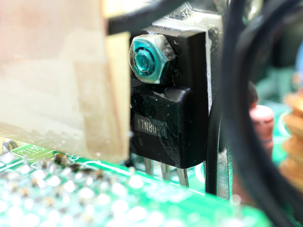
| Main Switcher | 1x Infineon SPA17N80C3 (800 V, 11 A @ 100 °C, 0.29 Ω) |
| Reset Switch | Fairchild FQPF3N80C (800 V, 1.9 A @ 100 °C, 4.8 Ω) |
| APFC/Switching Controller | FSP 6600 IC |
| Topology | Primary side: Active Clamp Reset Forward Secondary side: Synchronous Rectification & DC-DC converters |
| Secondary Side | |
| +12V MOSFETs | 2x Texas Instruments CSD19506KCS (80 V, 193 A @ 100 °C, 2.2 Ω) |
| 5V & 3.3V | DC-DC Converters: 4x Infineon BSC030N03LS G (30 V, 77 A @ 100 °C, 3 mΩ) PWM Controller: ANPEC APW7159C, FSP6601 |
| Filtering Capacitors | Electrolytics: Nippon Chemi-Con (105 °C, KZE, KZH) Polymers: Teapo |
| Supervisor IC | SITI PS113 |
| Fan Model | Protechnic Electric MGA8012YS-A15 (80 mm, 12 V, 0.28 A, Sleeve Bearing) |
| 5VSB Circuit | |
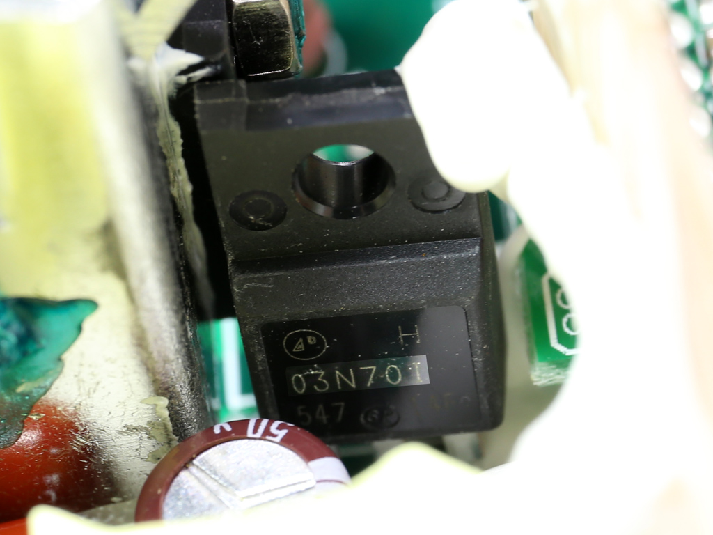
| Rectifier | 1x A-Power AP03N70I-H FET (700 V, 2.5 A, 4.4 Ω) |
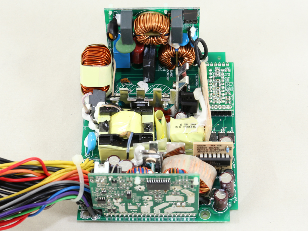
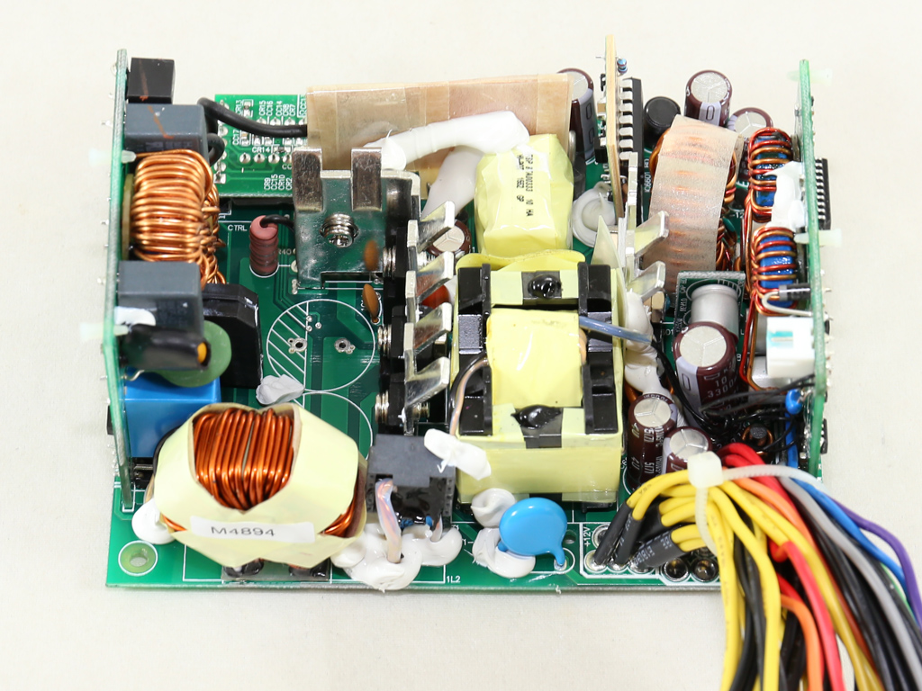
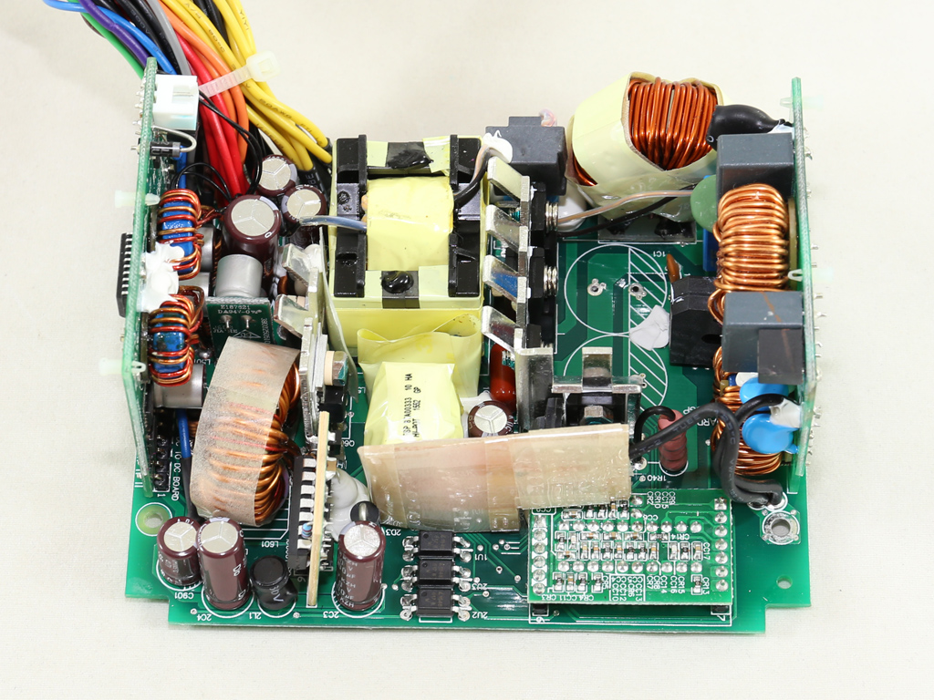
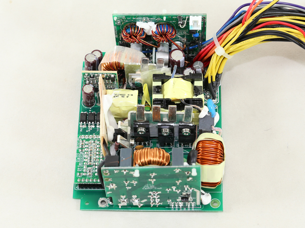
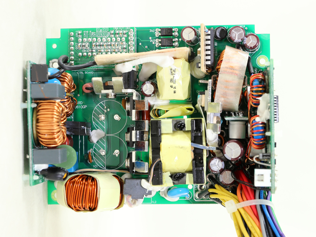
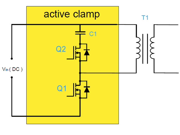
The SX550 is made by FSP, and the platform it's based on originates from the FSP550-50SGGBA. The topology used is referred to as Active Clamp Reset Forward (ACRF), which offers high efficiency and lower production cost since it doesn't need extra components like an LLC resonant converter. In low-capacity ACRF designs, two FETs are used. One of them is the main switcher (Q1) while the other one is a reset switch (Q2) responsible for disconnecting the clamp capacitor while Q1 is active. Power is transferred from the primary side to the secondary one only when Q2 is open. ACRF's strongest advantage is the almost lossless switching of Q1; while it's off, the drain voltage is very low.
When Q1 is active, voltage is applied to T1, meaning that power is transferred from the primary side to the secondary side. When Q2 (also called the auxiliary FET) is active, clamp voltage is applied to T1. The larger the clamp capacitor (C1), the lower the ripple voltage. However, a higher-capacity C1 also slows transient response. So, achieving the right balance is critical in an ACRF design.
As usual with modern high-efficiency PSUs, a synchronous design is used on the secondary side for rectifying the +12V rail, while the minor rails are regulated by a couple of DC-DC converters. The main PCB is tiny. In order to save space, the second part of the EMI filter, along with the bridge rectifiers, are installed on a vertical daughterboard. This might help reduce the space those components require, but it doesn't help with airflow, so operating temperatures will likely be higher. Finally, both installed heat sinks are pretty small. This, along with the cramped components, probably prevented SilverStone from using a semi-passive fan mode.
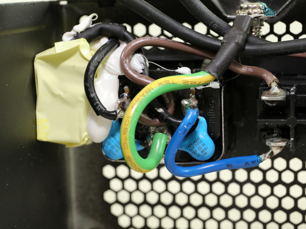
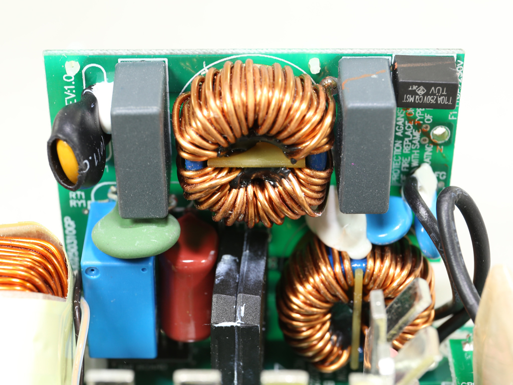
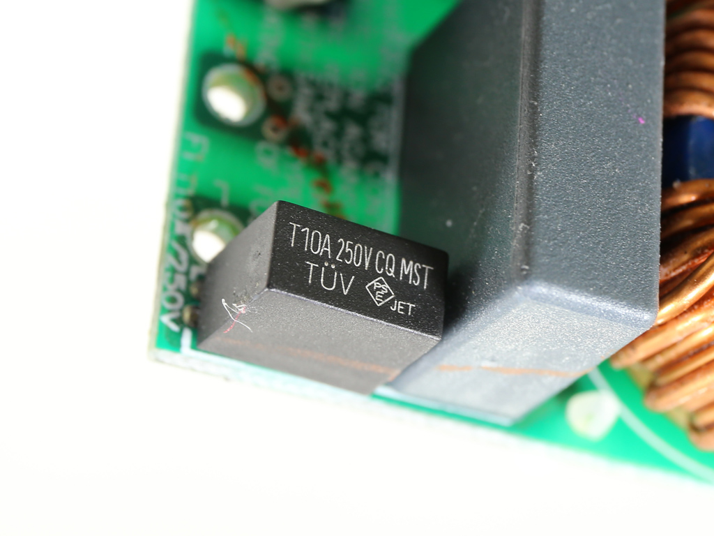
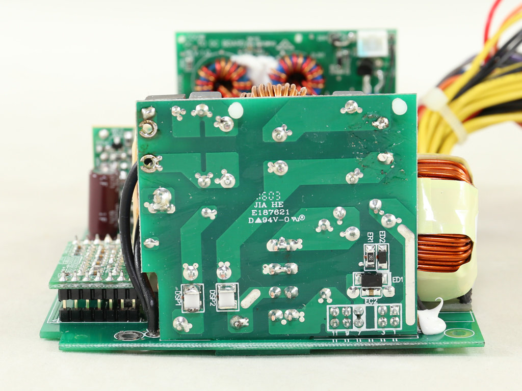
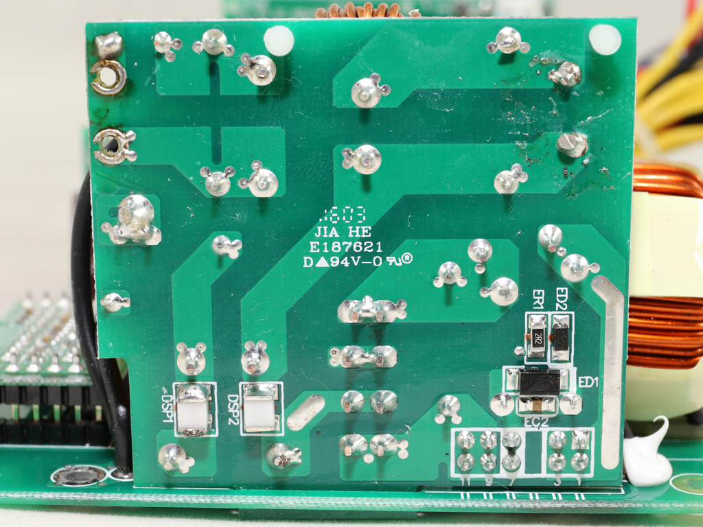
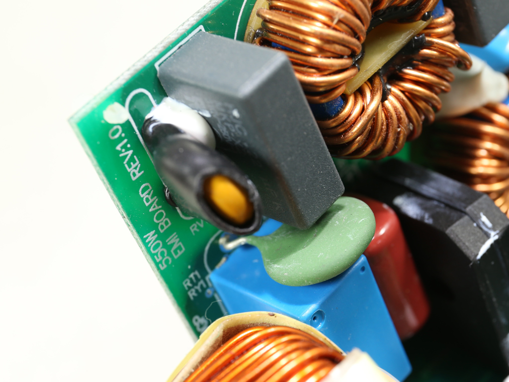
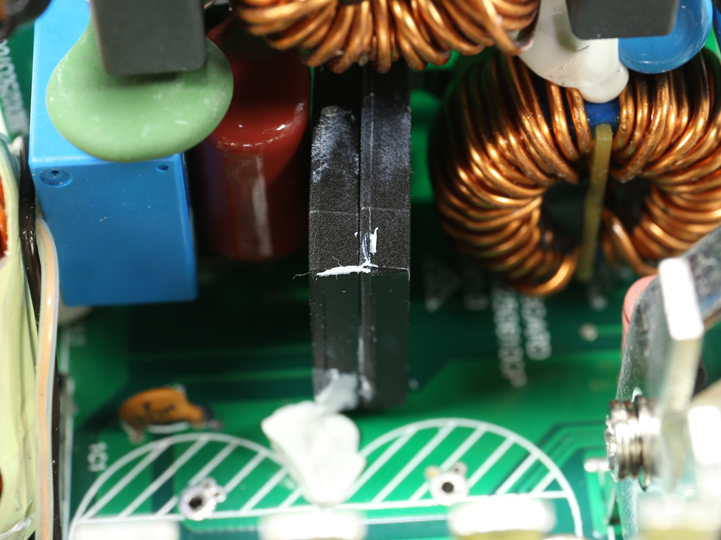
The first part of the EMI filter starts at the AC receptacle with two Y caps and a single X cap. It continues on the main PCB with two more X caps, a pair of Y ones, two CM chokes, and an MOV. As we already mentioned, the second part of the EMI filter is hosted on a vertical board. This was essential since there isn't enough space on the main PCB.
An NTC thermistor is used for inrush current protection. It's supported by a bypass relay that allows the thermistor to cool down quickly. On top of that, it slightly boosts efficiency since the thermistor has some resistance even at high operating temperatures.
The parallel bridge rectifiers (GBU10V06) aren't bolted on a heat sink. According to the official specification sheet, these rectifiers can handle up to 2.9 A at 100 °C without a sink. This means that they can handle 5.8 A combined, so with 115 VAC the max power handling is 667 W. This power level is very close to the PSU's max capacity if we take into account the efficiency level with full load delivery. SilverStone should advise FSP to use larger bridge rectifiers or find a way to cool the current ones with a heat sink in order to handle more amperage.
Get Tom's Hardware's best news and in-depth reviews, straight to your inbox.
The APFC converter uses a couple of Infineon IPA60R125CP FETs along with a single STMicroelectronics STTH8R06FP boost diode. The bulk caps are provided by Chemi-Con (420 V, 150 uF each, 2000 h @ 105 °C, KMG) and their combined capacity is enough to provide a long hold-up time. We should note that, in general, the ACRF topology achieves much higher hold-up times than other topologies.
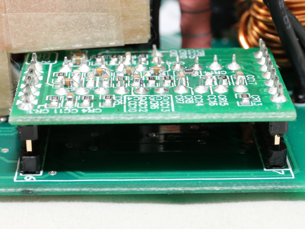
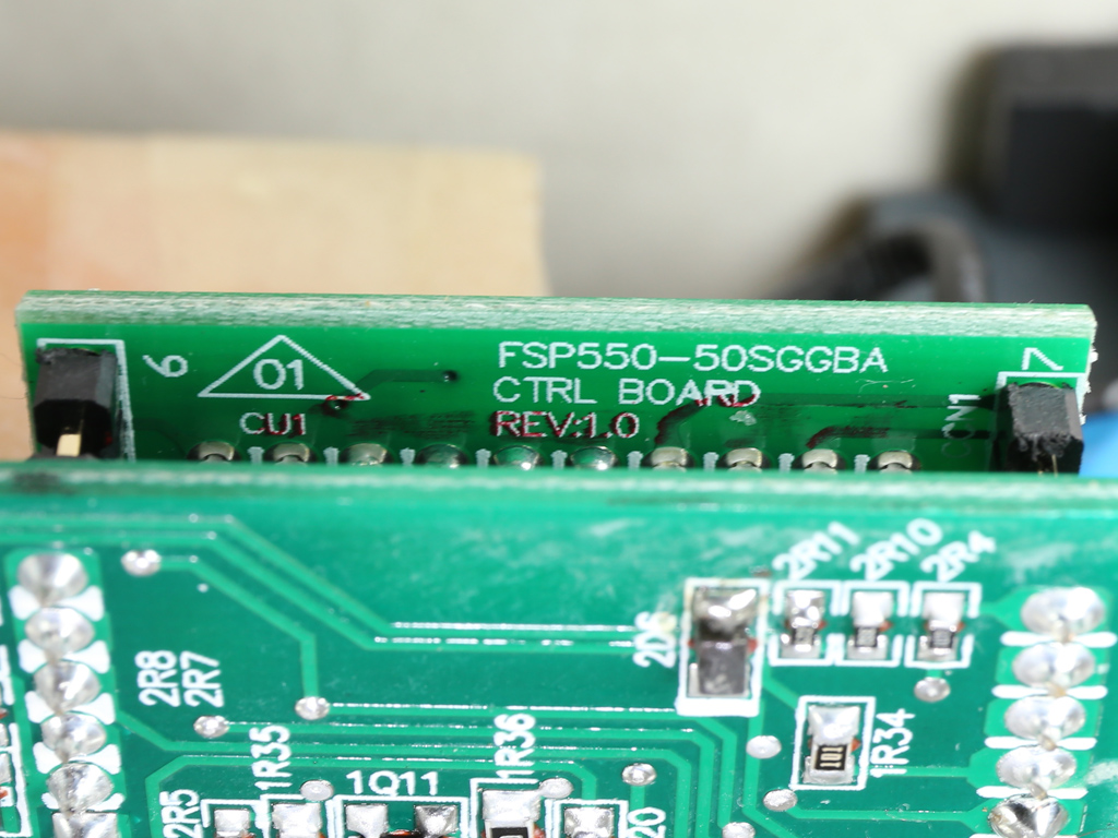
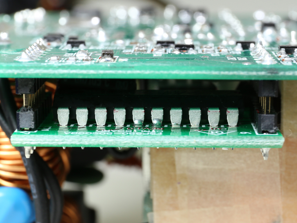
The PFC/PWM controller is the FSP 6600 IC for which there is no documentation available.
There are two primary switching FETs. The main one is a Infineon SPA17N80C3, while the auxiliary (reset) FET is a Fairchild FQPF3N80C. It might have some benefits (high efficiency per dollar and long hold-up time with smaller bulk caps). However, an ACRF platform generally cannot match the performance of other topologies, especially when it comes to transient response scenarios.
Right next to the main switchers is the 5 VSB rectifier, a single A-Power AP03N70I-H FET.
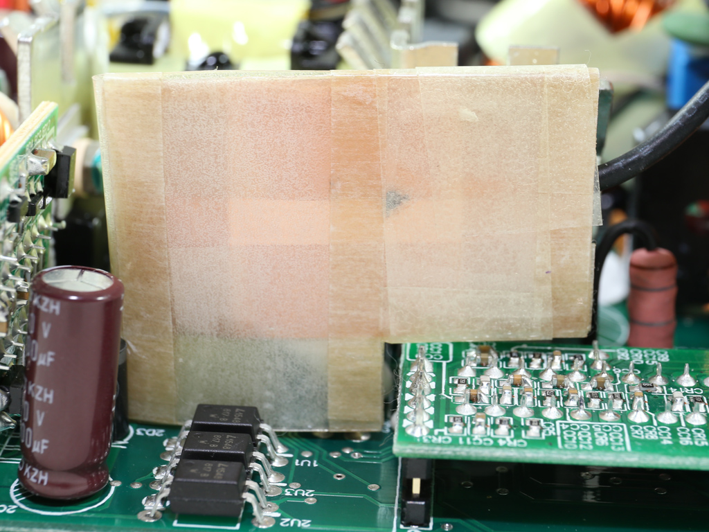
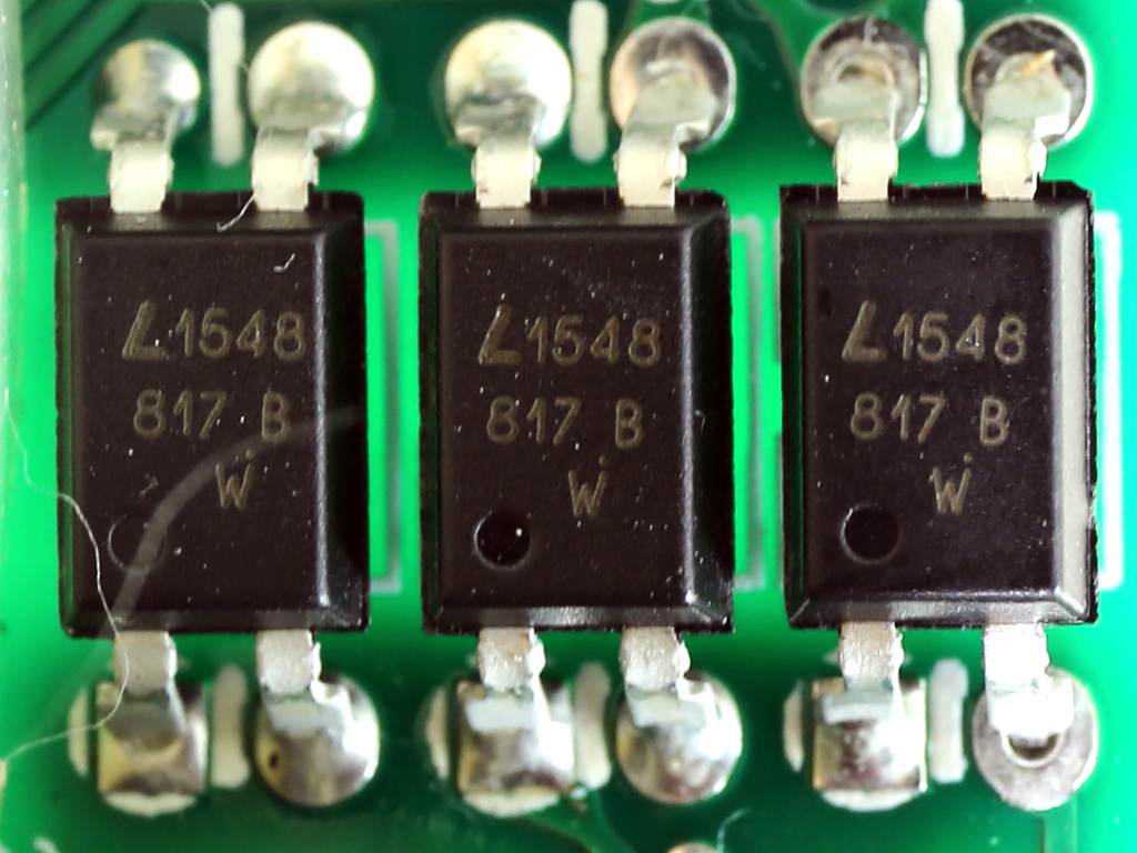
There is an EMI shield, which is grounded, between a number of optocouplers that isolate the primary side from the secondary and the main switching FETs.
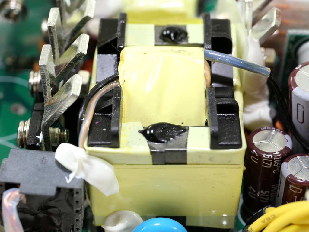
There seem to be two thermistors installed on the main transformer, providing temperature data to the fan control circuit and to the over-temperature protection.
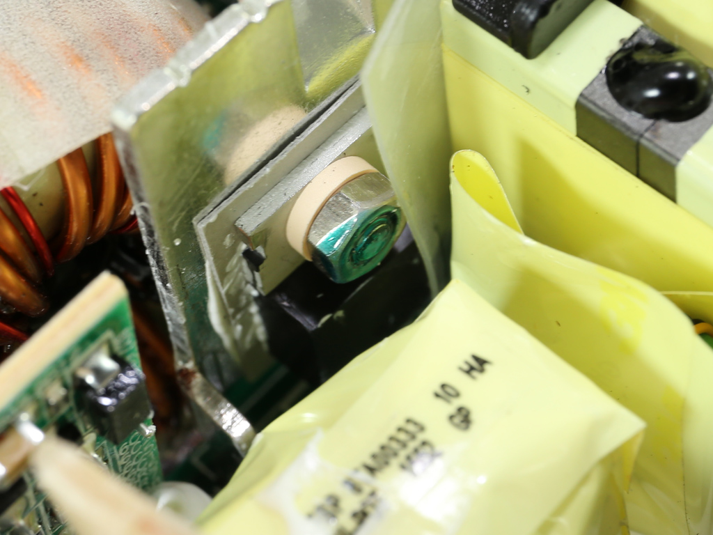

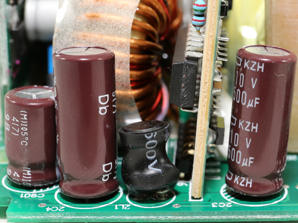
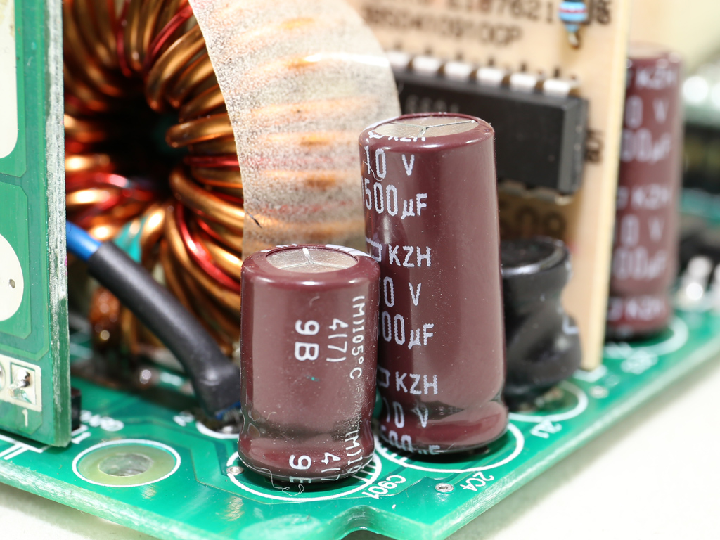
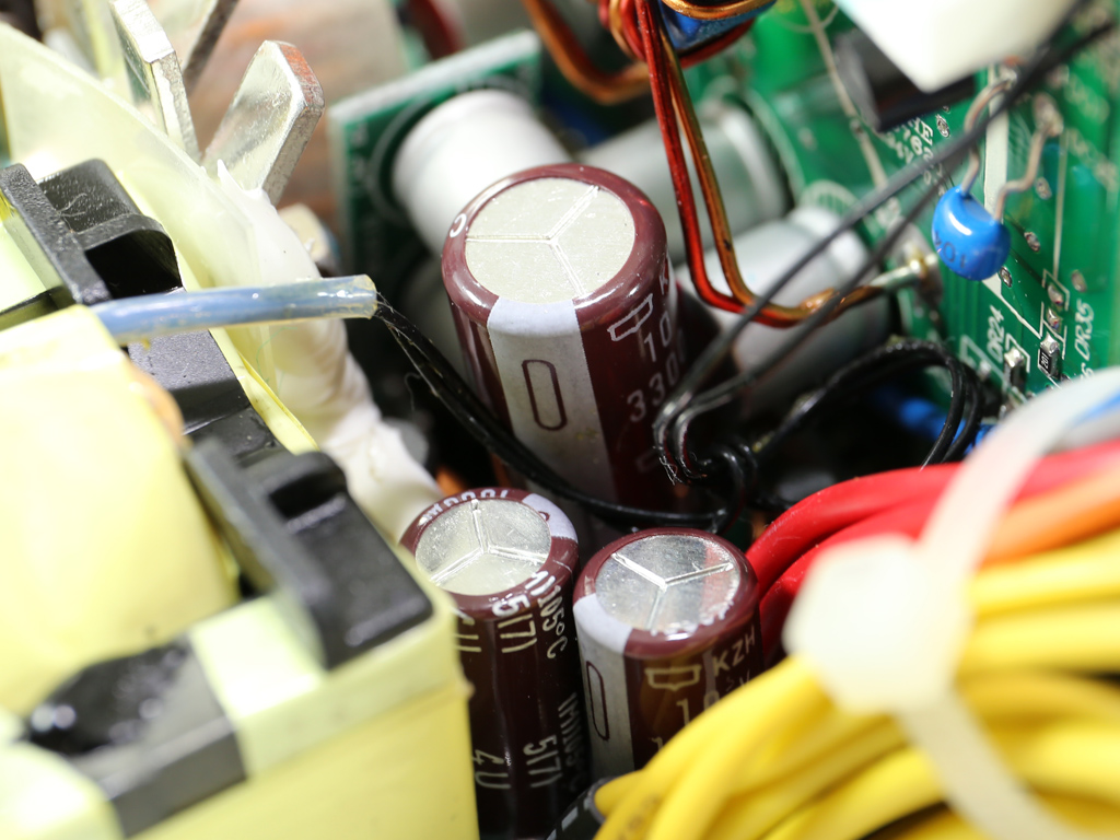
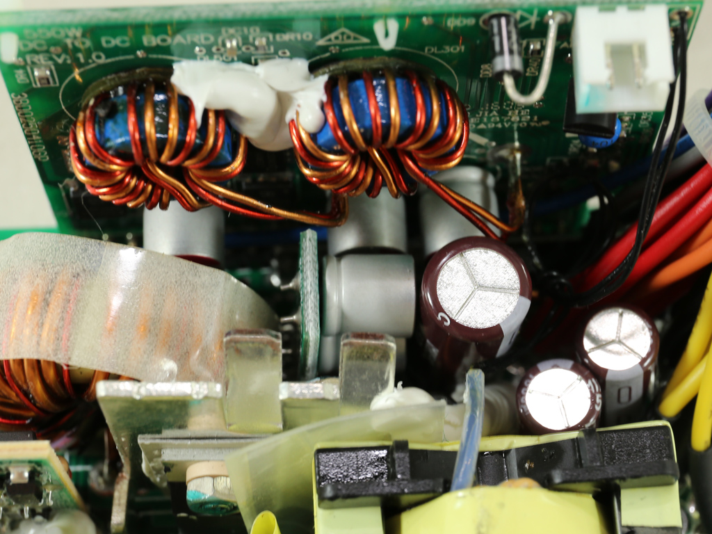
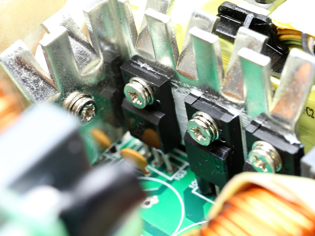
A small heat sink on the secondary side holds a pair of Texas Instruments CSD19506KCS FETs that regulate the +12V rail. The electrolytic filtering caps are provided by Nippon Chemi-Con. They're all rated at 105 °C. Besides electrolytic caps, a number of Teapo polymers are also used for filtering the DC outputs.
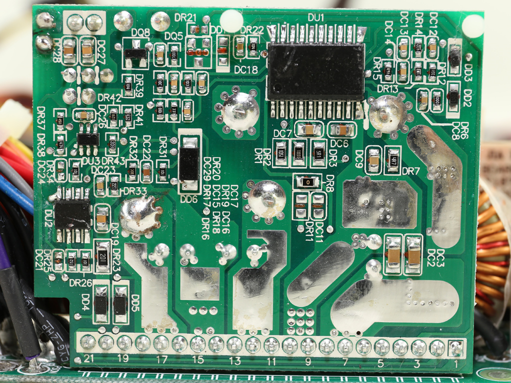
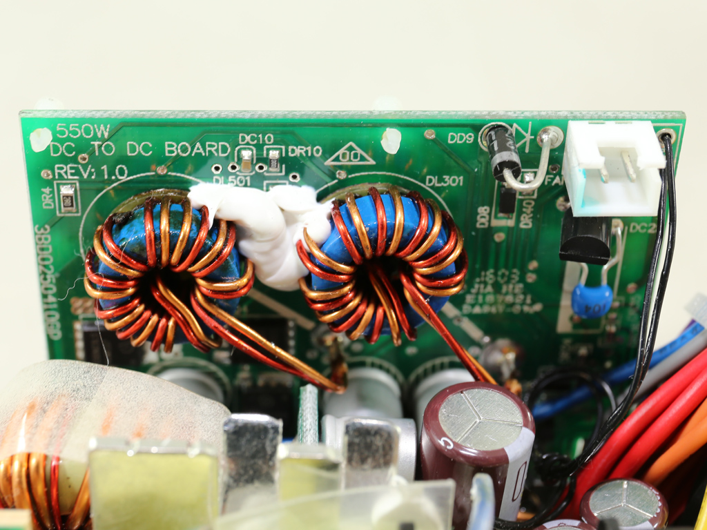
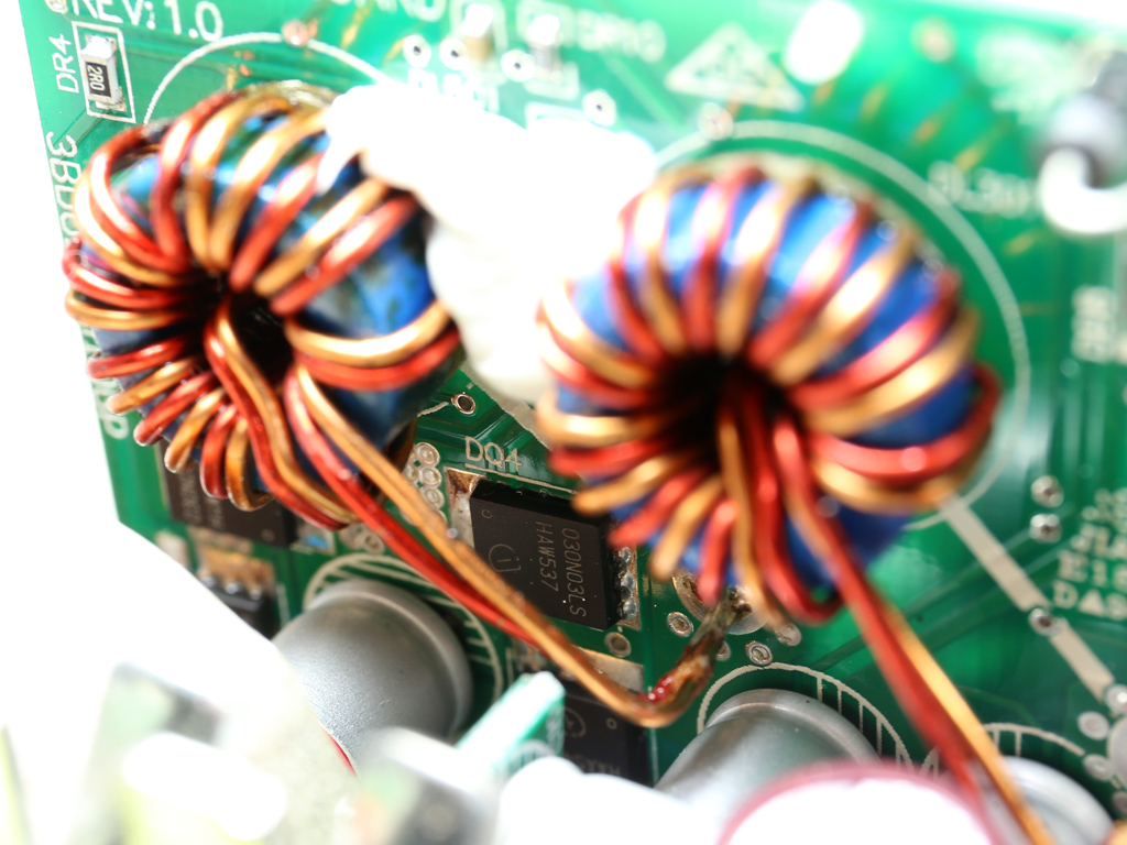
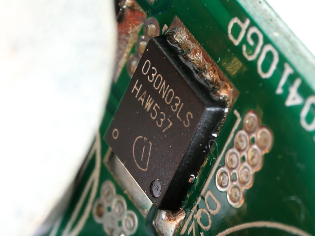
This large daughterboard on the secondary side hosts the supervisor IC, a SITI PS113, and both DC-DC converters responsible for generating the minor rails. In total, four Infineon BSC030N03LS G FETs are used by the aforementioned converters, and the PWM controller is an ANPEC APW7159C.
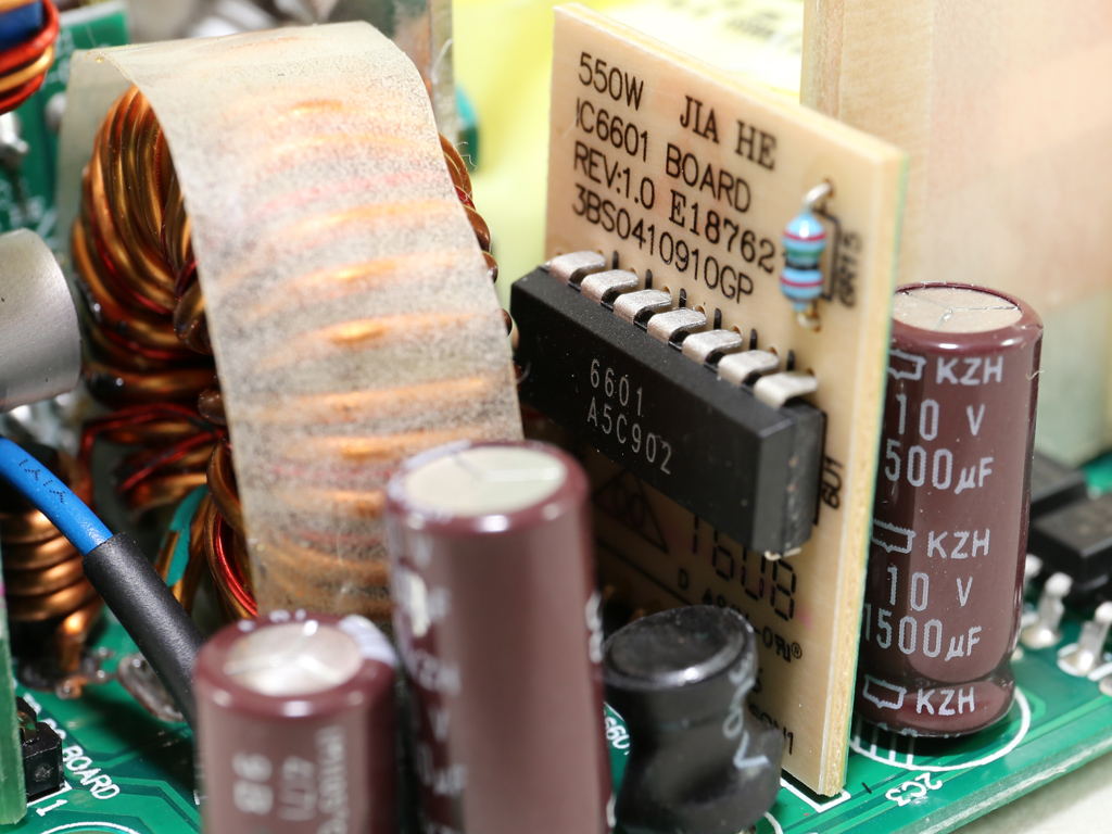
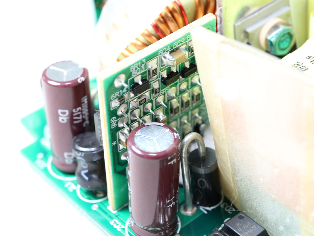
Besides the ANPEC PWM controller, we also found an FSP6601 IC for which there is no documentation. However, we strongly believe this IC is also used by the DC-DC converters that handle the minor rails.
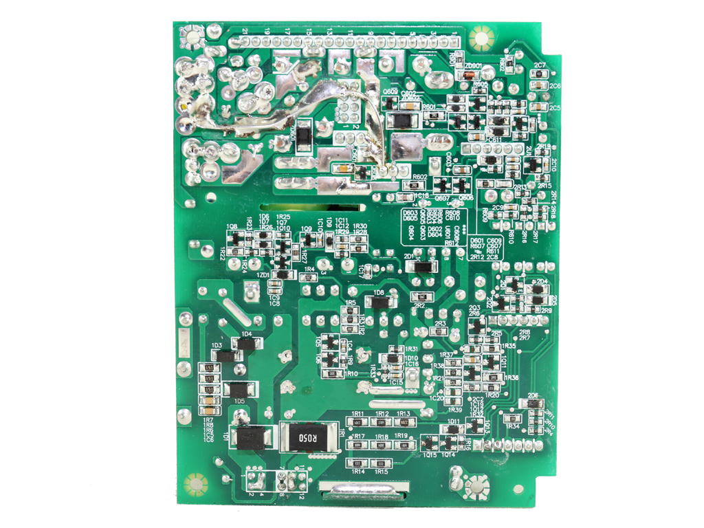
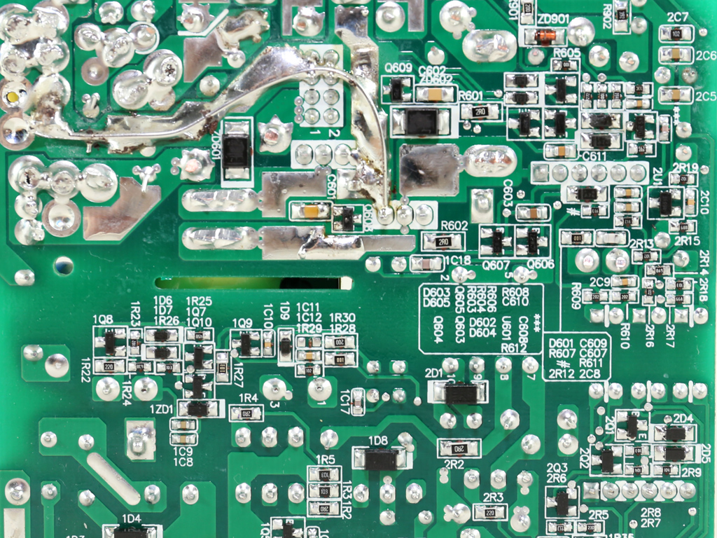
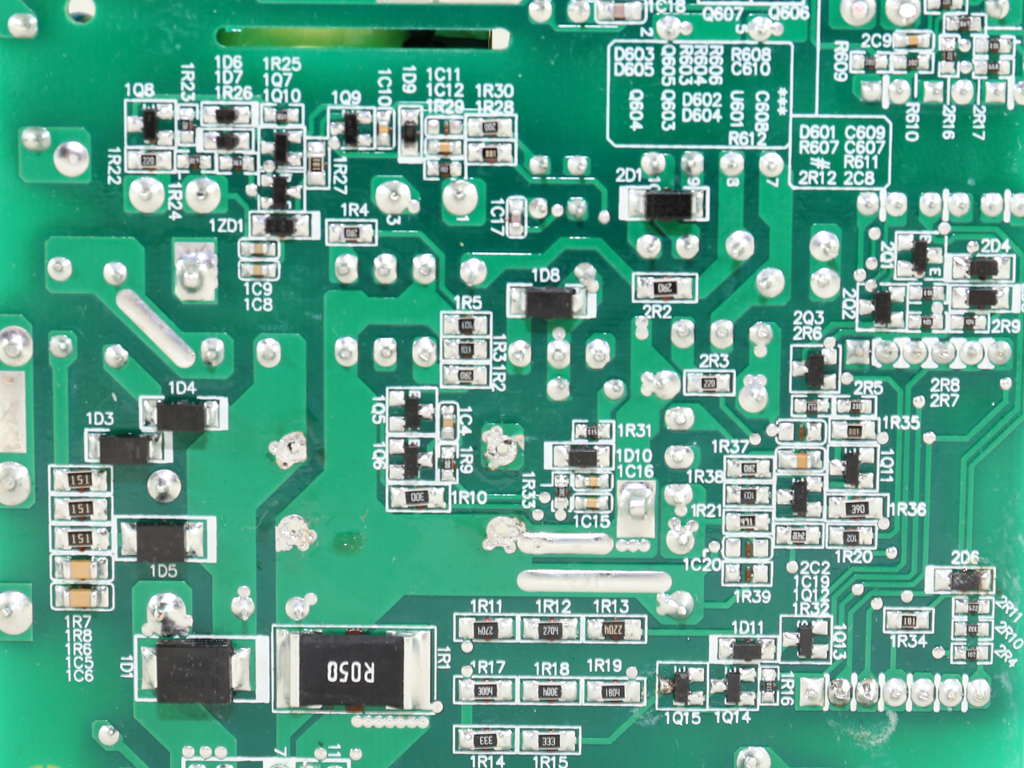
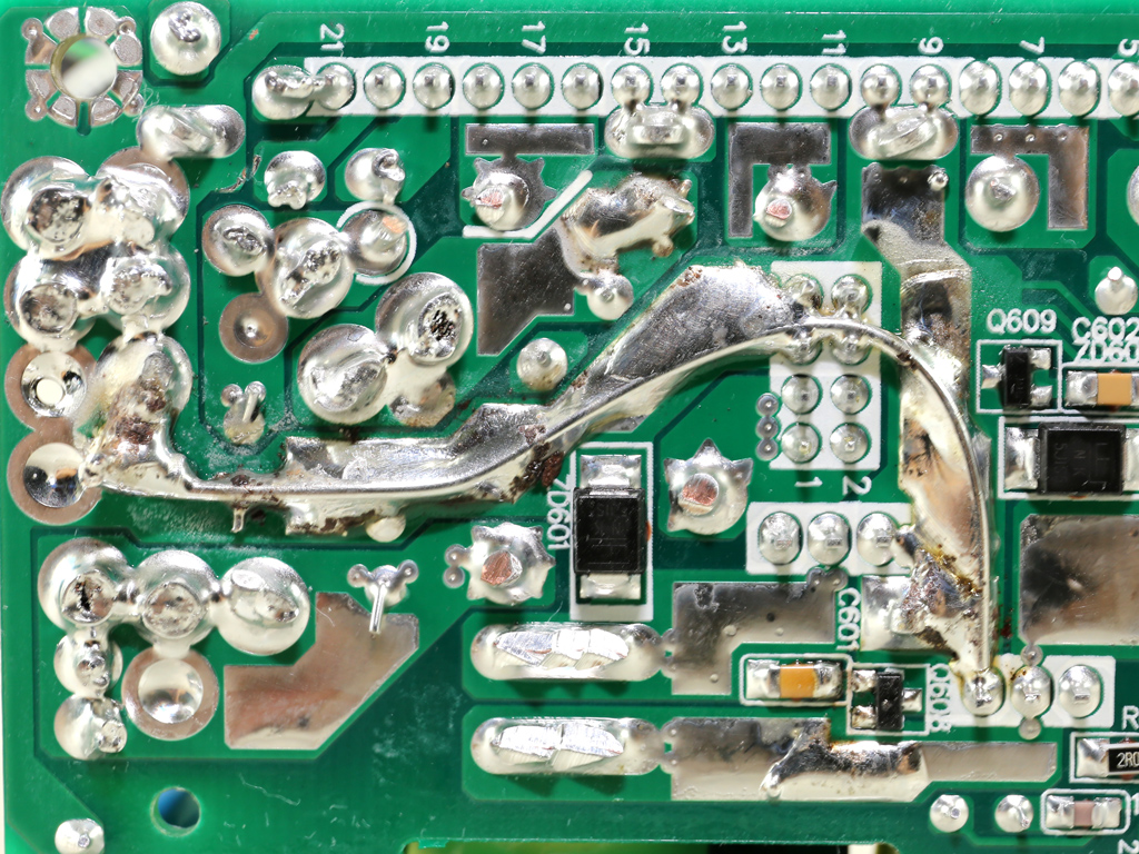
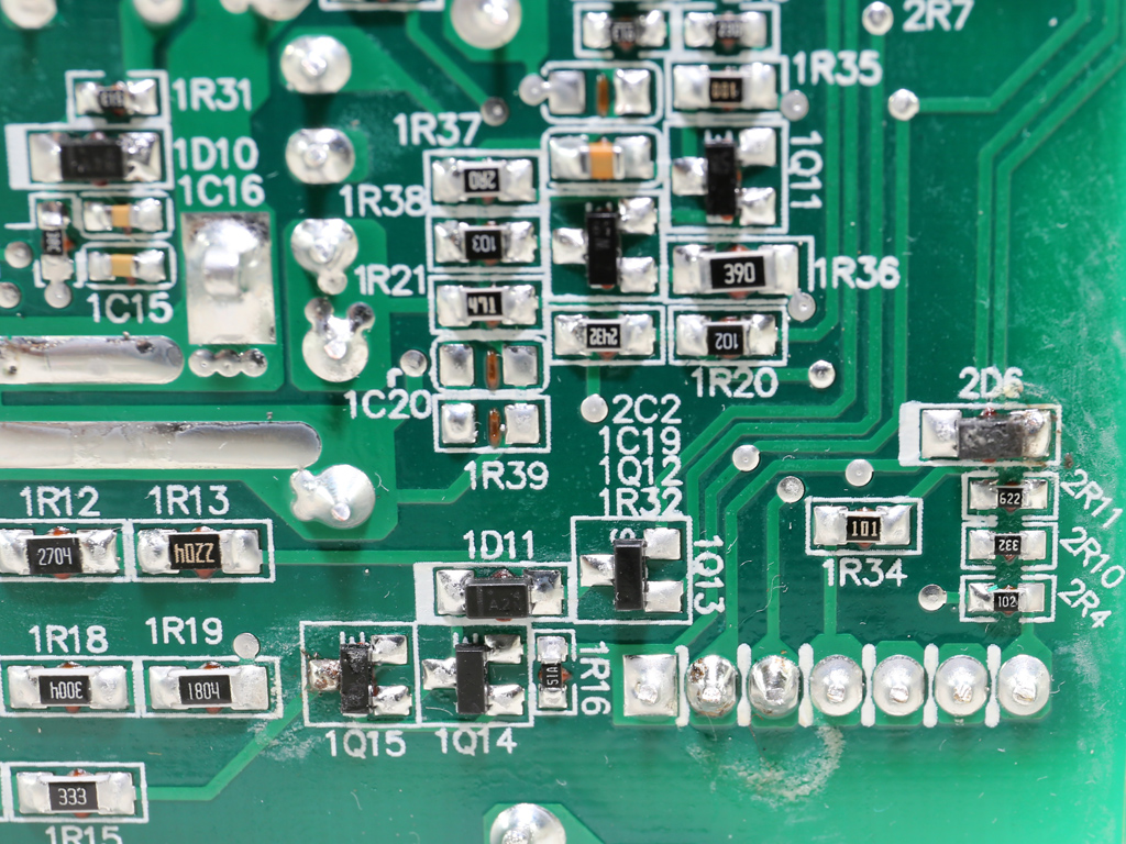
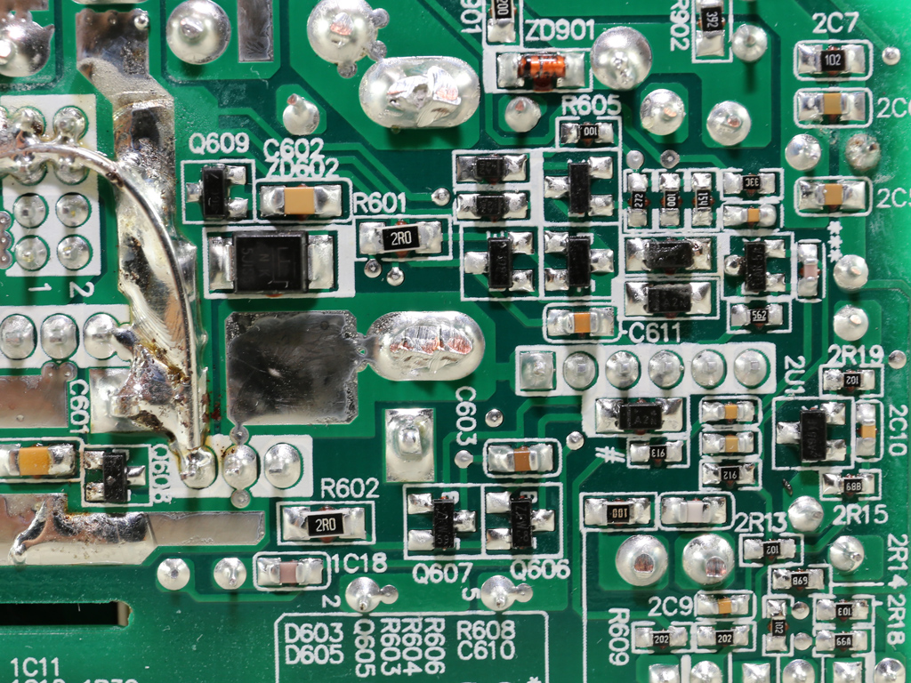
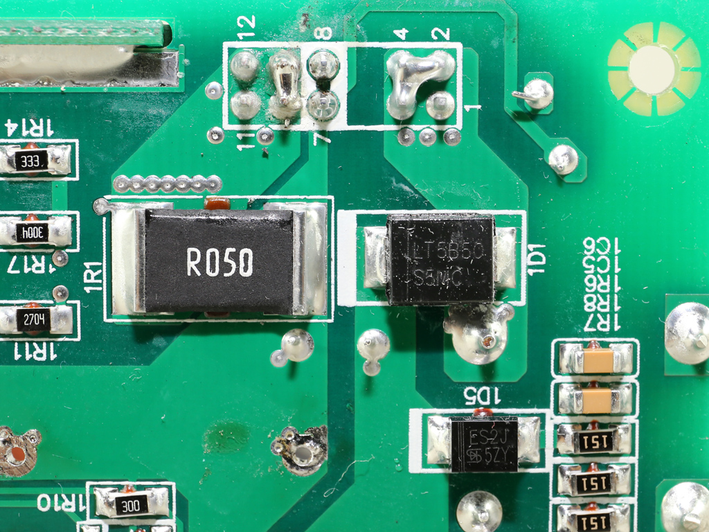
Soldering quality is decent, though it could be even better. We spotted some misaligned SMD parts and a not-so-nice PCB trace reinforced by a copper wire to increase the ground's conductivity.
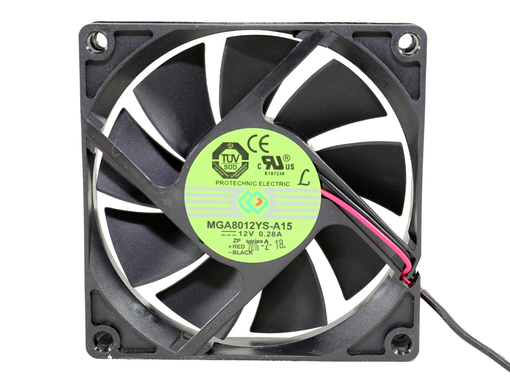
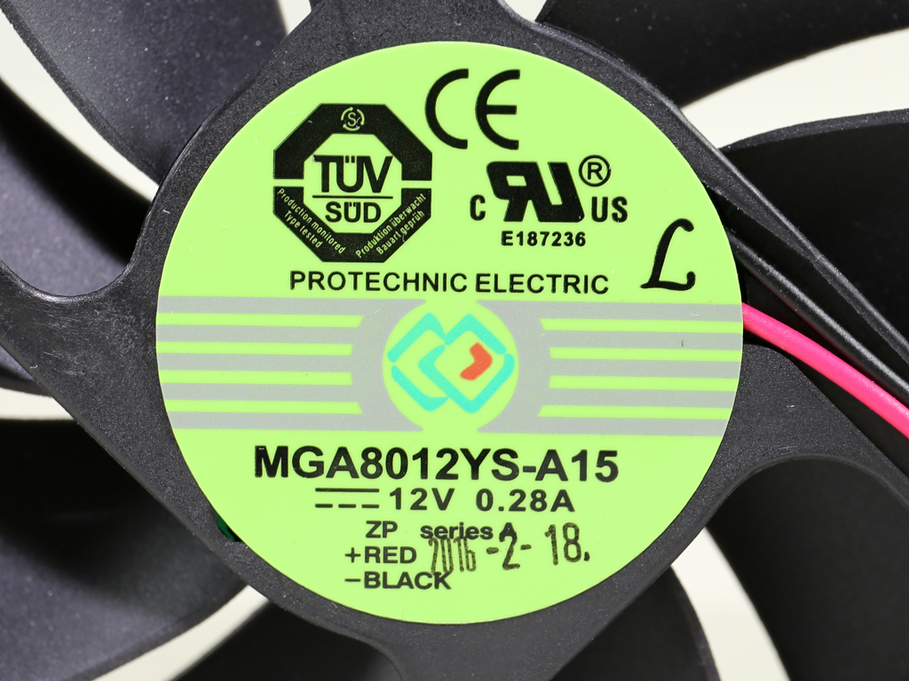
The fan is made by Protechnic Electric and its model number is MGA8012YS-A15 (80 mm, 12 V, 0.28 A). We measured 3570 RPM at top speed with our scope. However, SilverStone's profile didn't allow the fan to spin that fast throughout our tough tests. We recorded a peak of of 3345 RPM. The fan uses a sleeve bearing, which isn't an ideal choice, but at least Protechinic Electric is considered to be a good manufacturer. As a result, we expect this fan to last longer than other sleeve bearing fans.
Current page: A Look Inside And Component Analysis
Prev Page Packaging, Contents, Exterior And Cabling Next Page Load Regulation, Hold-Up Time And Inrush Current
Aris Mpitziopoulos is a contributing editor at Tom's Hardware, covering PSUs.
-
turkey3_scratch It doesn't seem like Silverstone can get anything right these days. I don't see how they can't include a rubber grommet where the wires leave the cage. When people are bending those wires around the case, they can easily rub up against a sharp edge like that and cut through the insulation or even damage the wires and increase the resistance. For $95 this is a rip off, I think it should be priced at $75. It's pretty loud, too.Reply
Also, according to your thing the PS113 doesn't support OTP, even though this unit seems to. It also seems to support UVP. Doesn't quite make sense to me. http://www.tomshardware.com/reviews/power-supplies-101,4193-22.html -
Aris_Mp Most supervisor ICs don't support OTP, so this protection is implemented through other circuits in PSUs that actually have OTP.Reply -
Clamyboy74 Having few cables is the point of an sfx psu. Sfx cases don't have much driver space, and short wires are good for small cases. Who in their right mind would but an sfx psu for use in a mod tower case, especially with a $95 price tag? When you review sfx psu's please bear into consideration that these are made for use in small cases, where short cables, few connectors are deal breakers for consumers. Thank you.Reply -
turkey3_scratch The thing that hurts this unit is that there is no common hardware configuration that will fit into an SFX case and require more than a 400W power supply like the Corsair SF which is much better. Most high-end AMD GPUs like the R9 390 are just way too large to even fit into an SFX case. If you think of cards that can actually fit into an SFX case, they are going to be small form factor cards, which are almost always under 200W, or these days even quite less. CPU overclocking to extremes can't be done in SFX cases with limited cooler sizes and due to airflow restrictions, so, really, I don't see a position in the market where this unit can be competitive over the Corsair SF400. And since this unit does not come with an SFX to ATX bracket, it is implied that nobody will probably install it into a case that takes an ATX PS2 power supply.Reply -
AlistairAB I have the corsaif sf450 and can confirm it blows the silverstone out of the water (silverstone never fixed their fan problems with their sfx psus)Reply -
Samer1970 Reply18459920 said:The thing that hurts this unit is that there is no common hardware configuration that will fit into an SFX case and require more than a 400W power supply like the Corsair SF which is much better. Most high-end AMD GPUs like the R9 390 are just way too large to even fit into an SFX case. If you think of cards that can actually fit into an SFX case, they are going to be small form factor cards, which are almost always under 200W, or these days even quite less. CPU overclocking to extremes can't be done in SFX cases with limited cooler sizes and due to airflow restrictions, so, really, I don't see a position in the market where this unit can be competitive over the Corsair SF400. And since this unit does not come with an SFX to ATX bracket, it is implied that nobody will probably install it into a case that takes an ATX PS2 power supply.
how about Titan X Pascal cards / 1080 ti? They consume 435Watt total System power.
-
turkey3_scratch Not quite samer and not cards that would fit in an SFX case.Reply
Also, my bad guys, I meant SF450 not 400. -
Samer1970 Reply18460559 said:Not quite samer and not cards that would fit in an SFX case.
Also, my bad guys, I meant SF450 not 400.
maybe you should check the following cases :
http://www.fractal-design.com/home/product/cases/node-series/node-202
http://www.silverstonetek.com/product.php?pid=533
http://www.silverstonetek.com/raven/products/index.php?model=RVZ02
https://www.ncases.com/
https://www.dan-cases.com/ -
turkey3_scratch If you own a 1080Ti why would you get a mediocre PSU like this anyway? Once again, it doesn't seem to have a purpose at all. Once power requirements get anywhere past 300W you probably have high-end hardware in which case a unit like this is a poor choice over the SF600.Reply
Budget power supplies over 500W really have no place in this world. People purchase budget power supplies over 500W for three reasons:
1) They have high end hardware and underestimate the need for a quality PSU
2) They are uninformed and think "more watts" is better.
3) They overestimate their power requirements.
I suppose you could argue if they have 225W of hardware a 550W unit like this is perfect in terms of efficiency. Okay, maybe so. But that depends on how much you value efficiency, I suppose.
The unit still performs poorly compared to Corsair. It's true, Corsair SF dominate the SFX market with the best units. -
Samer1970 Reply18460649 said:If you own a 1080Ti why would you get a mediocre PSU like this anyway? Once again, it doesn't seem to have a purpose at all. Once power requirements get anywhere past 300W you probably have high-end hardware in which case a unit like this is a poor choice over the SF600.
Budget power supplies over 500W really have no place in this world. People purchase budget power supplies over 500W for three reasons:
1) They have high end hardware and underestimate the need for a quality PSU
2) They are uninformed and think "more watts" is better.
3) They overestimate their power requirements.
I suppose you could argue if they have 225W of hardware a 550W unit like this is perfect in terms of efficiency. Okay, maybe so. But that depends on how much you value efficiency, I suppose.
The unit still performs poorly compared to Corsair. It's true, Corsair SF dominate the SFX market with the best units.
Does not need to be 1080 ti , any 250 watt GPU card ... from 390 , 390x to others .. there are people on budget and use such cards in compact systems .
I just mentioned gtx 1080 ti as a modern example ..
