TFT Guide - Part 1 - Flat Panel Displays
How TFTs Work
TFT stands for 'Thin Film Transistor' and describes the control elements that actively control the individual pixels. For this reason, one speaks of so-called 'active matrix TFTs'. How are images produced? The basic principle is quite simple: a panel with many pixels is used whereby each pixel can emit any color. To this purpose, a back light is used which is normally comprised of a number of flourescent tubes. In order to light a single pixel, all that needs to be done is for a small 'door' or 'shutter' to open to let the light pass through. The technology that makes this possible is of course more complicated and involved than the simple explanation above. LCD (Liquid Crystal Display) stands for monitors that are based on liquid crystals. Liquid crystals can change their molecular structure and therefore allow varying levels of light to pass through them (or they can block the light). Two polarizer filters, color filters and two alignment layers determine exactly how much light is allowed to pass and which colors are created. The layers are positioned between the two glass panels. A specific voltage is applied to the alignment layer, creating an electric field - which then aligns the liquid crystals. Each dot on the screen (pixel) therefore requires three components, one for red, green and blue - just as for the tubes within cathode ray tube devices.
The most common devices are Twisted Nematic TFTs . The following sections explain the way in which such TFTs work. A number of different technologies obviously exist. These are explained in part 2 - Viewing Angle Technologies .
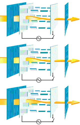
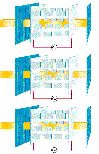
Figure 2a: How a Standard TFT (Twisted Nematic) Display works
When no voltage is applied, the molecule structures are in their natural state and twisted by 90 degrees. The light emitted by the back light can then pass through the structure.
Figure 2b: How a Standard TFT (twisted nematic) works
If a voltage is applied, i.e. an electric field is created, the liquid crystals are twisted so that they are vertically aligned. The polarized light is then absorbed by the second polarizer. Light can therefore not leave the TFT display at this location.
Architecture Of A TFT Pixel
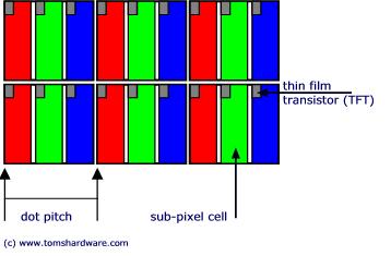
The color filters for red, green and blue are integrated on to the glass substrate next to each other. Each pixel (dot) is comprised of three of these color cells or sub-pixel elements. This means that with a resolution of 1280 x 1024 pixels, exactly 3840 x 1024 transistors and pixel elements exist. The dot or pixel pitch for a 15.1 inch TFT (1024 x 768 pixels) is about 0.0188 inch (or 0.30 mm) and for an 18.1 inch TFT (1280 x 1024 pixels) it's about 0.011 inch (or 0.28 mm).
Get Tom's Hardware's best news and in-depth reviews, straight to your inbox.
Figure 4: Pixels of a TFT. The left upper corner of a cell incorporates a T hin F ilm T ransistor. Color filters allow the cells to change their RGB basic colors.
The pixels are decisive and the smaller their spacing, the higher the maximum possible resolution. However, TFTs are also subject to physical limitations due to the maximum display area. With a diagonal of 15 inch (or about 38 cm) and a dot pitch of 0.0117 inch (0.297 mm), it makes little sense to have a resolution of 1280 x 1024. Part 4 of this report covers the relationship between dot pitch and diagonal dimensions in more detail.
Current page: How TFTs Work
Prev Page Manufacturing And Yields Next Page What Causes The Unpleasant Scaling Errors?-
viktor3600 Hi!Reply
I am marjan ,and I have nokia 6303c with this type of display (I think) and I work in service for SYSMEX in my country and one day I spray my nokia with WURTH spray for contact ,next day on my nokia screen has shown lots of big black dots .What should I do to remove this dots .
Please send me an answere to my E-mail :marjanarsov@hotmail.com


