Tuning Extreme: Overclocking with the Asus A7V
Building Instruction: A Maximum Core Voltage Of 2.32 Volts
Before we begin with the actual modification, you should have the following utensils ready:
- Low-power soldering iron with a fine tip
- Resistor with 24 KOhm (performance class 1/4 W)
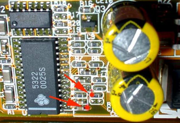
On the Asus A7V the VRM module resides on a separate circuit board. With a resistor we create an additional connection to this controller IC, which enables higher CPU core voltages. To explain it in more detail: A controller IC (CS5322) sits next to the MOSFET transistors on the small switch controller board.
This circuit controls the MOSFET transistors, which receive digital input signals from the CPU. The 24 KOhm resistor that is connected to the input part of the controller IC distorts the incoming control signal from the CPU. The result: The MOSFET transistors send a higher core voltage to the CPU.
Installing the resistor changes the core voltage, which means the preset values in the Asus A7V BIOS do not match the actual voltages. This problem can be addressed with our table that contains the adjusted voltages in relation to the values in the BIOS.
Small modification - big effect: A 24 KOhm resistor is soldered to these two pins. Attention: SMD resistors that do not tolerate too much heat are connected to both pins.
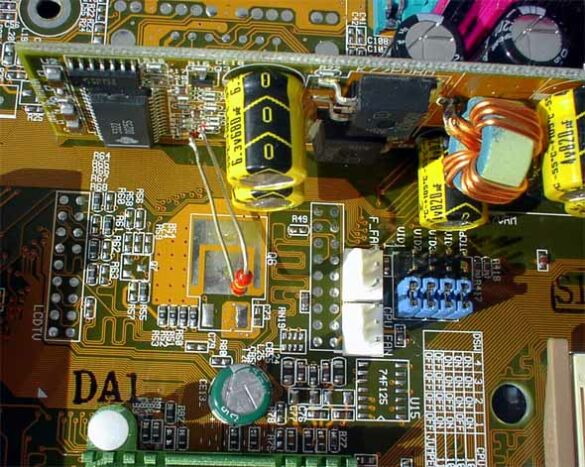
Top view of the modified VRM module: The resistor has been soldered in and generates a permanent core voltage of up to 2.32 Volts.
Get Tom's Hardware's best news and in-depth reviews, straight to your inbox.
Current page: Building Instruction: A Maximum Core Voltage Of 2.32 Volts
Prev Page CPU Core Voltage As The Limiting Factor Next Page Choosing The Correct Core Voltage
