Tear-Down: Let's Take a Trip Inside A UPS
In response to our power bar tear-down, many of you asked to see a UPS receive the same treatment. So, today, we go on a tour inside a vintage APC BX1000.
Silk Road
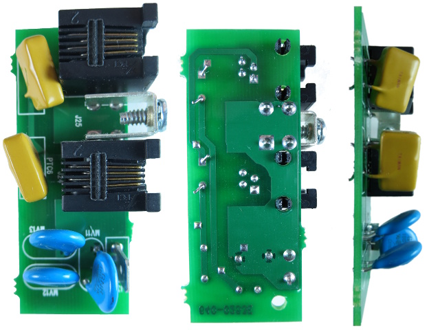
This little critter resides in the middle of the rear cover, atop the rows of power outlets.
Two 600 150 FLEI (Or is that FLE1? Either way, I could not find specifications) devices in series with the phone input lines, one GNR 10D271K MOV directly across lines, and one more from each line to ground make up the BX1000's phone line protection circuitry. Two-hundred-seventy volts seems like a high clamping voltage for the phone line compared to the SurgeArrest's 175 V. There's no soldered ground wire; the ground wire connects on the tab partially hidden by the MOV labeled MV11.
The silkscreen implies that these two parts from Taiwan are positive thermal coefficient devices of some sort, and sure enough, their resistance does increase with temperature. It looks like these are intended to play the role of self-healing fuses.
The Iron Lump
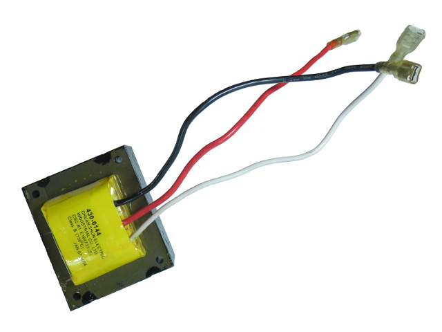
The BX1000 comes equipped with APC's Automatic Voltage Regulation. AVR functionality works by inserting this transformer wired as an auto-transformer in the AC signal path to either boost line voltage by a few volts when wired in-phase or buck it by a similar amount when wired in anti-phase. Two relays control which configuration, if any, gets activated. It's a little crude, but the good old iron lump is a simple, reliable, and efficient way of doing coarse voltage regulation. Many dedicated AVR units are fundamentally the same design, but with multiple taps on their transformer for finer-grained adjustments across a wider input/output range.
The Main Course
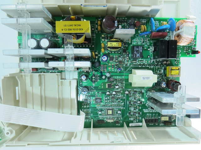
In the top-right corner, we have the input noise and surge suppression filter that many enthusiasts are already familiar with from seeing similar device configurations in power supply reviews. Halfway across the top, there's a small component cluster consistent with a simple low-power switching power supply. Farther to the left, we see six thick, aluminum plate heatsinks and a substantial high-frequency transformer, hinting that something big must be going on over there.
Another pair of heatsink plates draws attention to the bottom-right corner, though their purpose is not immediately obvious from this angle (unless you know exactly how this type of UPS works). All heatsinks are crowned with a clear plastic clip to maintain spacing between plates; APC is not leaving anything to chance.
The bottom-left quadrant of the board contains the monitoring and control magic, with the USB interface micro-controller located along the bottom-right edge.
Get Tom's Hardware's best news and in-depth reviews, straight to your inbox.
A Shell Off Itself
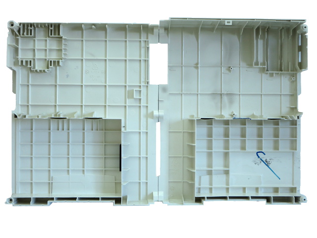
With the main board yanked out, the housing is stripped bare.
Both halves are extensively ribbed for stiffness, and the outer walls are thick enough that the recessed APC brand on the outside does not show through on the inside. Extra ribbing is present around the iron-core transformer and battery areas to help spread mechanical stress from their weight.
Near the center of the right half and above, where the main PCB used to be, there's a thin coat of soot-like residue. But I saw no immediately evident source on the board. My best guess is that a "hot potato" has been slow-roasting dust and possibly other materials, and the natural convection caused this fine particulate matter to slowly accumulate on the housing over the past 10 years.
Flippy Board
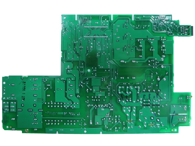
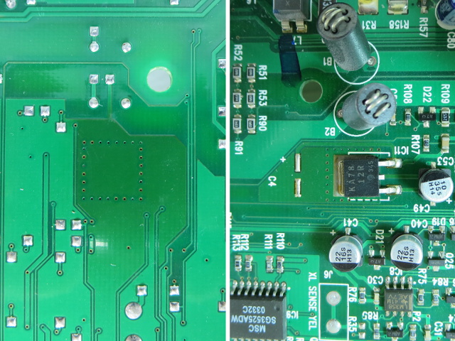
Looking good for a decade-old board, isn't it? The PCB looks exactly as it should for a wave-soldering job, except for a slightly darkened area just above the hole near the center, indicating that whatever lies on the component side uses PCB copper pours as its heatsink and dissipates a fair amount of heat. This might explain the soot-like residue on the back cover, and the location is about just right, too. What could our mystery device possibly be?
Hot Potato
Since the PCB blemish is the only detail that grabbed my attention, let's take a look at it first.
Our toasty chip here is a KA7812R, a Fairchild Semiconductor +12 V linear regulator. As anyone familiar with linear regulators can tell you, it is common for these little beasties to run hot. In this case, it likely takes the output voltage from the switching supply presumably used to charge the batteries and power relays, which means about 27 V, and drops it to 12 V for lower-voltage circuitry, such as operational amplifiers and possibly the low-voltage MOSFET drivers on the battery-powered side.
On both PCB surfaces, it is fascinating how the discoloration stops almost exactly at the copper pour boundaries, demonstrating how much more effective paper-thin copper pour and via-stitching (the row of tiny plated holes through the PCB around the IC) are at spreading heat than fiberglass alone. The technique becomes even more effective in board designs with one or more ground and power planes.
Access Denied
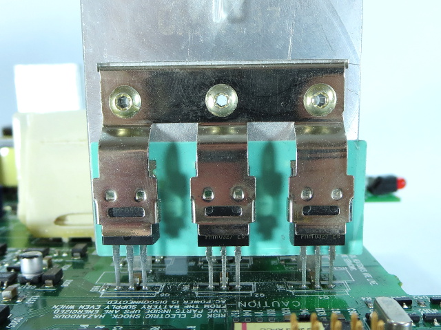
All devices mounted on heat sinks are riveted in place and won't go anywhere. Components with incompatible tab connections get the insulation strip and riveted retaining steel clip treatment, which hides most of the device information. In this picture, the slot on the leftmost device happens to line up with the device model, revealing it to be an IRF640.
Writing on the board reminds us that high voltage may still be present, even when the unit is unplugged from the wall, if the batteries are still connected. Another warning along the right edge of the board informs us that heat sinks may carry live voltage. Good thing the line power and battery were disconnected for a while before I even started removing housing screws.
The Obligatory Input Shot
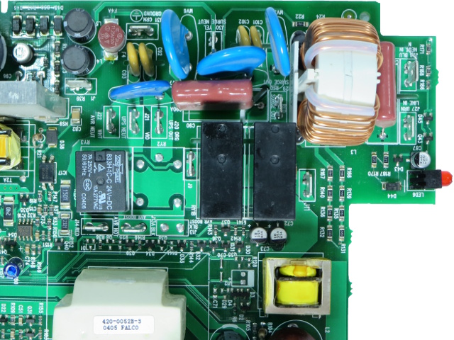
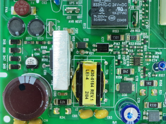
Just like nearly every other line-powered piece of electronics, the BX1000 has one X-capacitor on each side of its large input choke, four Y-capacitors, three 20D361K, and one S18K150 MOVs, providing filtering and surge suppression along the top edge. Three hundred and sixty volts seems high to start clamping in a 120 V UPS. But then again, battery-powered loads get switched out when line voltage exceeds the configured limit.
Below those, we see the battery-power transfer relay, the two AVR relays, two surface-mount resistor ladders likely used by the micro-controller to sense line input voltage, and the wiring fault indicator LED. The small yellow transformer farther down provides current sensing for the battery-backup outlets, enabling the micro-controller and PC software to calculate how much power the attached devices are using.
Let There Be Light
Even power supplies need some power for themselves, and the BX1000 gets its juice from a TOP234Y highly integrated fly-back switching regulator rated for up to 45 W output on 85-265 VAC line input, which is more than enough to charge the UPS' batteries and run everything else. At a glance, the circuit configuration looks like one of the TOP23x reference designs, give or take a few application-specific tweaks.
The stubby line input capacitor is about half the height of a typical 680 µF 200 V device, but actually is only a 47 µF part rated for 450 V, which is surprising large for such a low capacity. The 450 V rating was also unexpected since there is no input voltage doubler; a 200-250 V device would have been sufficient. Continuing the overrated component theme, the surface-mount diodes are S1K types rated for 800 V reverse voltage and 1 A forward current. It looks like the circuit is clearly designed for reuse across APC's 115 and 230 V products, and the company decided to forgo shaving pennies by tweaking the BoM for individual line voltage ranges. That's not surprising, considering how the housing, and presumably the PCB, span at least two rating models in both 115 and 230 V flavors.
Brains!
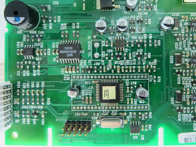
This board area may not look particularly exciting, but the micro-controller hidden under that sticker controls battery charging, AVR relay configuration, the high-voltage DC-DC converter, the line/battery transfer relay, the high-voltage "modified sine wave" output MOSFET switching sequence, and a piezoelectric buzzer to wake you up at 2 A.M. when there is a power blip if you forget to either turn that feature off or at least configure a delay on it.
Also present in the area are a few operational amplifiers to help with monitoring various signals, such as battery voltage, output voltage, and output current; a PWM controller for the battery side of things (more on that later); and a ton of (de-)coupling capacitors.
-
blackmagnum Thanks Daniel for the interesting write up of this old beauty. I have always trusted APC for my electricity supply backups.Reply -
olsaltydog Good article, I find it funny you just put this up. I just turned in a 8 page research paper on UPS systems and the potential technology that could replace the traditional lead-acid UPS/ Diesel Generator combination. Could have used you in part of my paper for a citation.Reply -
Daniel Sauvageau Reply
I actually sent in this article two weeks ago. It just happened to finish bubbling up the editorial pipeline last weekend and get a publication slot today.14138873 said:Good article, I find it funny you just put this up. I just turned in a 8 page research paper on UPS systems and the potential technology that could replace the traditional lead-acid UPS/ Diesel Generator combination. Could have used you in part of my paper for a citation.
As for replacements for the good old UPS + Generator combo, I presume you mean things like the Bloom Box - basically a fuel-cell-powered UPS - removes the lead, the acid, periodic battery replacement, periodic maintenance on the mechanical parts, etc. from the equation. -
olsaltydog Yeah one portion of the paper dealt with the Bloom Box being implemented and used by Microsoft, E-bay, and Apple. Another part of the paper was about just replacing the lead acid batteries themselves with the Durathon battery design created by GE. Only thing is GE's battery will be used in larger applications just like the Bloom Box. The last portion I researched was how Hybrid topologies where essentially a combination of of the Star and Bus/Ring topologies you could essentially create a new entire category of UPS' by integrating the UPS into the generator itself.Reply
Im just glad the paper is done and the UPS's we have at work dont need their batteries replaced hopefully for another few years. The ones we are using have a tray of about 20-26 batteries linked together and can make a great sparkler if the terminals make contacts to the wrong parts. -
f-14 ReplyHaving trouble unlocking your "slightly used" UPS to take a look inside? At the top of the BX1000, there is a snap about halfway in at the top holding the shell's two halves together. Its location is circled in red on this picture. You need a long, flat screwdriver to easily reach and disengage it.
or go to your utensil draw and grab those chop sticks you've been saving! -
rahulkmr391 i have a APC Back UPS RS600 which i purchased in june 2011 and its battery has been replaced on april of 2014 it worked fine till august of 2014 suddenly it it stated to give me problems it was refusing to start up but battery power was working but it refuses to supply power to my equipment when i asked tech support they said the main Board has to be changed the reason they said to me is fluctuation killed my ups. what an utter piece of junk, my older ups served me for about 9 years with regular battery changes but the apc one died in less than 3yrs is this what apc makes quality ups..?Reply -
olsaltydog So you had one failure with how many long lasting APC UPS' out there. UPS' have many parts that can wear or fail at some point and should not be looked at as the ultimate safeguard. They can fail and most people find that out when they need it not to. I know it sucks but this one instance you had with APC probably should not deter you from their product. Check online if the model has been having issues then yeah avoid it, no different then what we do with power supplies which is a good reason there is a list here on site. Other then that I have seen many types of there products hold strong and true for years, hope your next experience even if with another company goes better.Reply
