Tripp-Lite isobar Surge Protector Tear-Down
Hallowed Out
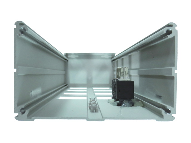
With everything but the glued-down switch removed, all that is left is the three-sided shell. You can clearly see the classic extruded aluminum body shape with screw channels near each corner and the groove the rear cover slips into at the top.
Extruded aluminum enclosures are convenient when you manufacture a range of products that require slightly different lengths of the same general shape. Order full-length runs and cut them down to whatever size you require.
Spilling The Beans
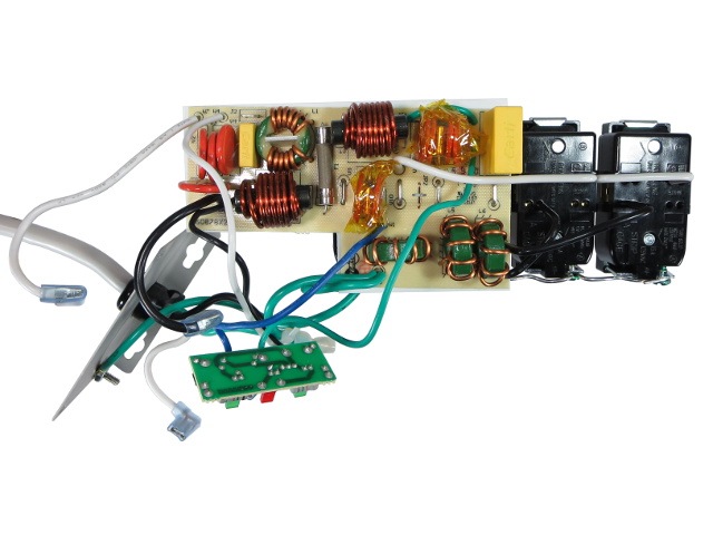
Unlike the box shot, where the diagnostic PCB is shown with all of its wires neatly tied together, the wires are actually all over the shop. It didn't look like there was this much wiring in here, based on Tripp-Lite's shot.
Something Troublesome
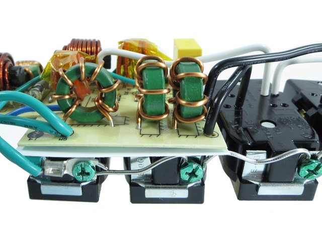
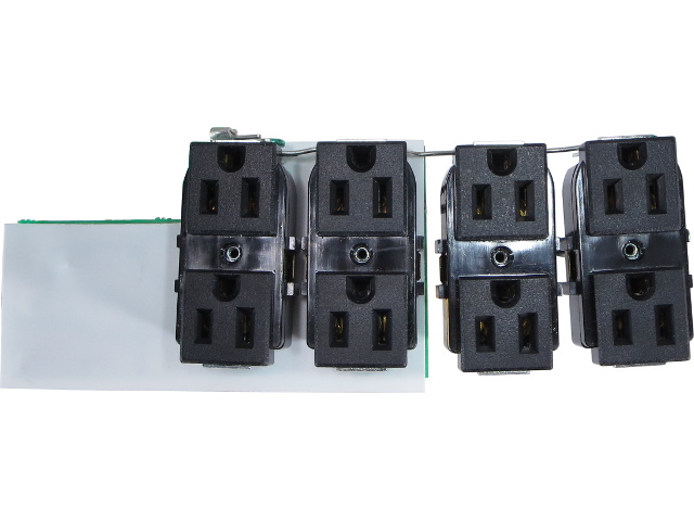
I see something potentially troublesome: the two outlets on the right are connected using rear-entry solid wires, while the other two on the left are connected directly to the PCB.
Along the bottom, you can see the daisy-chained ground connections, starting with the PCB's ground wire on the left crimped to another wire using a fork connector.
Hitting A Snag
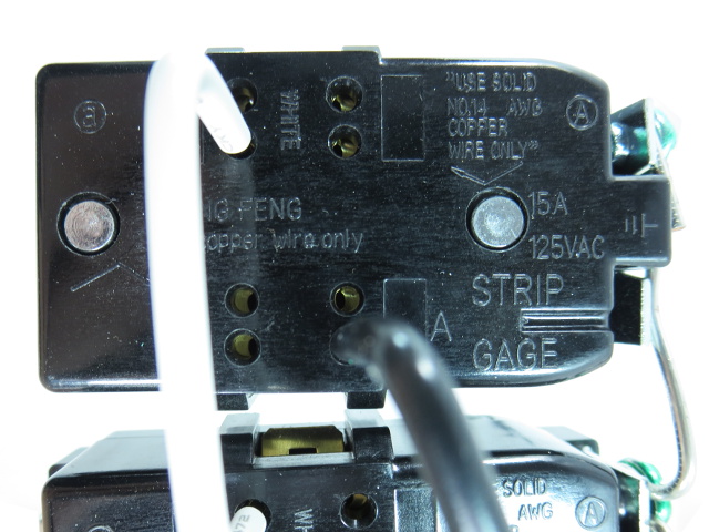
These Rong Feng outlets with snare-type connections have no wire release slots. Even if they did, those slots are usually on the back, which would be of no help with the two outlets nailed directly through the PCB.
What The Packaging Says
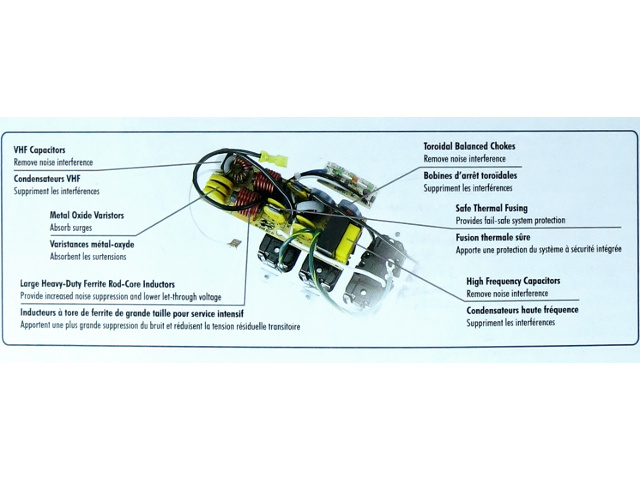
Here is a closer look at that PCB image for reference purposes. On it, we can see three fat MOVs, a small X-cap and a common-mode choke on the left edge. A pair of chunky inductors, six more skinny MOVs (only one pair of which equipped with a visible thermal cut-off), three toroidal inductors and two more X-caps are on the right edge.
Get Tom's Hardware's best news and in-depth reviews, straight to your inbox.
What You Actually Get
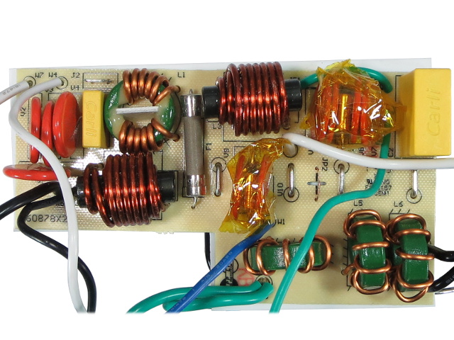
The PCB has four skinnier-looking MOVs on the left. The two inductors got shifted further apart, presumably to reduce mutual inductance. Two MOV pairs got grouped around a single thermal fuse. And there is only one X-cap at the board's right edge instead of two in the artwork version.
Upon examining the PCB, I cannot help wondering where the “isolated filter banks” advertised on the packaging actually are, unless the company means those toroidal inductors at the bottom are the only isolation between banks.
Wound Up
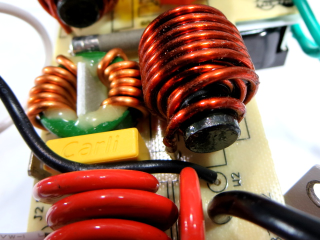
The front end of both large inductors looks like whoever wound them had a hard time making the wire go from the top layer to component lead cleanly. Since these inductors could be blocking over 2kV during a surge, I am surprised they rely exclusively on their enamel coating to prevent arcing between layers. The first and third layer wires are also crossing quite close to each other.
The other components comprising the isobar's line input are four Ceramate 20D391K, a 100nF Carli X2 cap, a common-mode choke and a 15A fuse. I was surprised to see MOVs rated at 390V here, instead of the usual 200V 20D201K.
Back-End
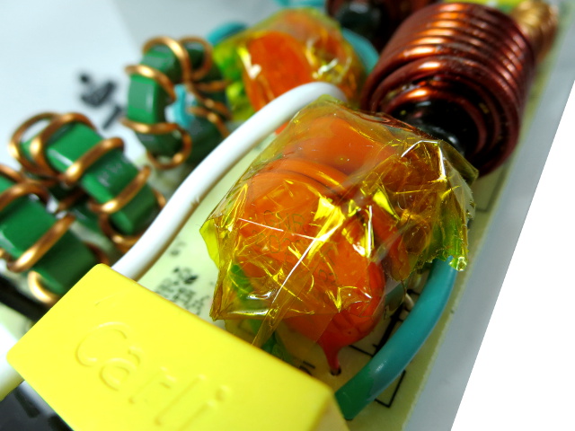
All six MOVs in this shot are the expected 20D201K. The two at the top are across live and neutral after the large ferrite bead inductors, while the four at the bottom are split between live-ground and neutral-ground. A 1µF X2 Carli cap completes the isobar's bulk filtering circuit.
Drawing A Blank
There is not a lot to see from below, since the whole PCB is covered by a sheet of heat-resistant material pinned down by two of the four outlets.
Nailed
Those outlets are not going anywhere, either. As mentioned, they are nailed directly through the PCB by a pair of gauge 14 jumpers through two holes on each side. Since I could not even manage to pull one of the single wires out of the wired outlets, there is no chance of prying outlets off the PCB without wrecking something.
If you were wondering about the wimpy-looking piece of wire in the middle, that's a fusible link between the four N-G/L-G MOVs and ground.
-
blackmagnum "How many people actually use their power bars' outlet covers?" I do. They protect the power bar from pest such as ants, pets and toddlers.Reply -
Kewlx25 My only wish is they had a 10 port version. I have a lot of low wattage electrical devices to plug in and the warranty says plugging this into another surge-protector or plugging another surge-protector into it voids the warranty.Reply
I've tried to find a non-surge-protecting power strip, but no luck. -
ralanahm Thank you for the review. I am glad to see these turned out better than lower price ones and it wasn't all marketing hype.Reply -
cbrunnem whats up with this guys/sites hard on for power strips.... can you not think of better things to review?Reply -
ralanahm Thank you for the review. I am glad to see these turned out better than lower price ones and it wasn't all marketing hype.Reply -
nukemaster Reply15622774 said:whats up with this guys/sites hard on for power strips.... can you not think of better things to review?
The community reaction to the early power bar tear down was positive.
If you do not want to see these, just do not read them.
This author is very good at breaking these things down so users can see and understand what is happening inside the power bars they sell at the store.
Tom's Hardware has other reviews and reviewers. -
froozeball Thank you both for the review and the chance (ie the actual product) to review!Reply
Always insightful, well presented and very useful. Frankly it's about time somebody really tore down, explained, and held these products accountable to the public. You explain issues to the point, good or bad, and it's a great piece of technology journalism that you present.
Felicitations et merci! -
Daniel Sauvageau Reply
All the sub-$15 power strips I have looked at are simple MOV affairs: power cord -> switch/breaker -> MOV(s) with thermal fuse -> outlets. For most electrical applications, they are indistinguishable from a plain strip unless something goes wrong since a 20D201K MOV conducts less than 1mA until voltage passes 200V. Under normal circumstances, 120V line voltage peaks at 170V so the MOV does practically nothing. You may also want to consider the fact that most of your electronics with a line-operated switchmode PSU likely has an EMI filter and MOVs of their own, which means they have much more complex impedance than a basic surge-protecting strip.15622264 said:I've tried to find a non-surge-protecting power strip, but no luck.
The warning against daisy-chaining surge protectors is more about the possibility of loose connections between strips degrading protection on downstream strips, over-loading strips and other issues which may affect surge protection performance or safety.
I have a few different things in the works but I need to put together a few test jigs first to make my life easier. If you do not like power-related accessory tear-downs, you are free to not read them.15622774 said:whats up with this guys/sites hard on for power strips.... can you not think of better things to review?
That said, I am starting to run out of tear-down candidates in that department, so I plan to do something else every other month to stretch those out, like the LCD tear-down/repair that came out last month. -
Daniel Sauvageau Reply
It is comments like those that make the ridiculous number of hours it takes to put these things together worth it. The tear-downs may look very simple but between planning, workbench and editing time, I likely spend more than an hour on average on each slide that makes it in.15623007 said:Thank you both for the review and the chance (ie the actual product) to review!
Always insightful, well presented and very useful. Frankly it's about time somebody really tore down, explained, and held these products accountable to the public. You explain issues to the point, good or bad, and it's a great piece of technology journalism that you present.
Felicitations et merci! -
gtinut heat shielding material? you must kidding. It is standard to place no conductive layer on metal where components are located.Reply
