Tripp-Lite isobar Surge Protector Tear-Down
The Usual Warnings
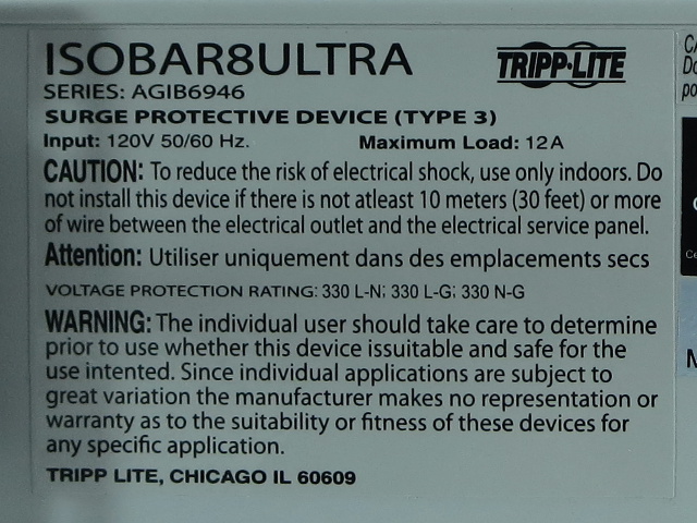
Turning the unit over reveals the usual indoors-only, dry location, 10m of in-wall wiring from the breaker box and daisy-chaining warnings. French-speakers again appear exempt from everything except dry locations. Surprisingly enough, the unit is only rated for 12A instead of the usual 15A; this is not mentioned in the packaging's specifications area.
The second warning blob mentions that the isobar might not be suitable for use under certain circumstances. I do not remember seeing this on any of the products we've dismantled in the past (or their documentation).
The Other End
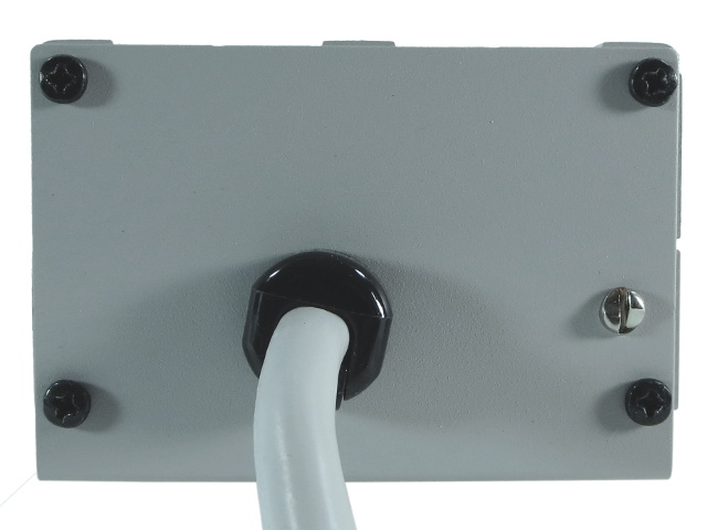
Aside from a cable entry point, there is not much to see here other than a fifth oddly placed screw. More curiously, that extra screw happens to be one of those non-reversible flat-heads. What does it actually do? Time to start digging in.
Short-Lived Mystery
Four screws later, the mystery is solved. That extra screw is merely a ground connection. Looks like Tripp-Lite did not want anyone loosening the ground screw without meaning to. This may seem redundant next to the quadruple grounding through the outlets' center screws, but safety rules require a non-structural ground attachment since outlet screws may loosen over time from normal use.
Slip-Sliding Along
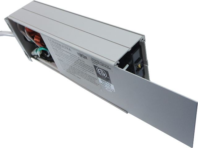
With either end cap removed, the rear cover effortlessly slides out of its housing track.
Cover Up
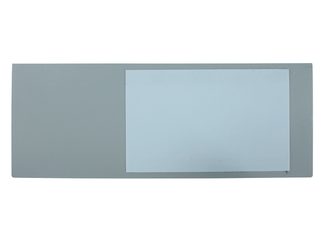
A thin piece of what appears to be heat-shielding material is stuck on the rear cover over the PCB's area, further reducing the amount of thermal exposure for whatever lies behind in case of a contained fire.
Surprise!
When I first received the retail box and saw the PCB image on the back, I thought it might spoil the tear-down surprise if they happened to match. So, I secretly hoped they wouldn't.
Get Tom's Hardware's best news and in-depth reviews, straight to your inbox.
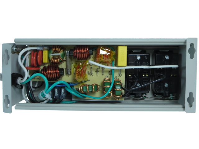
With the rear cover out of the way, we have a glimpse of the internals. If you remember back to the packaging's PCB image, you may notice that the PCB shape and layout are completely different.
House Of Spades
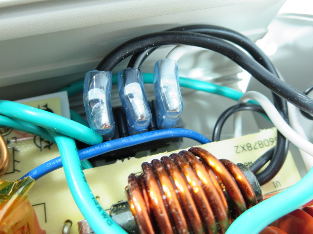
All except one connection between the PCB, the power cord and breaker switch use spade terminals. The ground wire gets crimped to another piece of wire, which is in turn soldered to the PCB.
Crimped Space
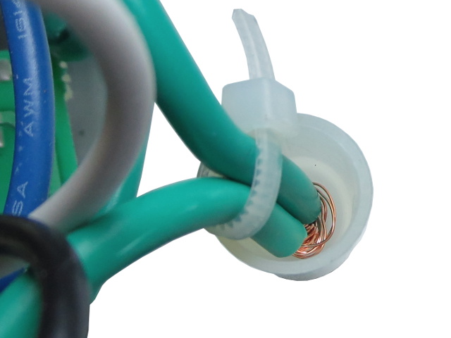
When you thread wires using crimp connections, you want all of the strands inside for best performance and also to ensure the tightest possible crimp. From the looks of it, the wires got rammed straight inside and a handful of their strands crumpled during insertion. This isn't ideal, but it's good enough to earn a “QC pass” sticker from automated testing.
Diagnostic
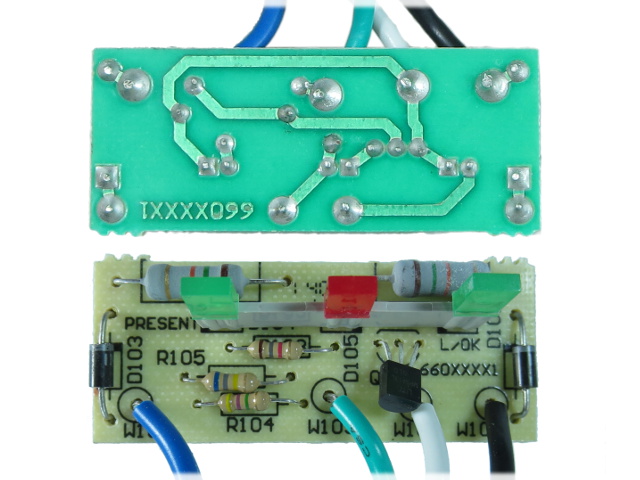
The Protection Present, Fault and Line OK Diagnostic functions announced on the housing's silk-screen are provided by this small PCB made from the main PCB's cut-out, which is a great way of reducing waste and manufacturing costs.
Hot Snot
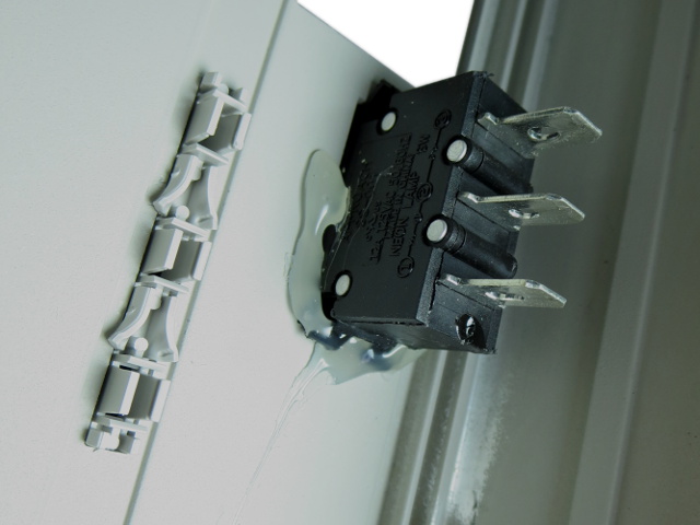
What do you do when your snap-in panel mount breaker is rattling slightly? You gunk it up. While duct tape often gets credit for holding the universe together, I believe hot glue deserves an honorable mention.
In case you were wondering, this is an Approach SS-001 12A/125V snap-in breaker. The oddly shaped plastic piece on the left is the LED holder for the status indicator PCB.
-
blackmagnum "How many people actually use their power bars' outlet covers?" I do. They protect the power bar from pest such as ants, pets and toddlers.Reply -
Kewlx25 My only wish is they had a 10 port version. I have a lot of low wattage electrical devices to plug in and the warranty says plugging this into another surge-protector or plugging another surge-protector into it voids the warranty.Reply
I've tried to find a non-surge-protecting power strip, but no luck. -
ralanahm Thank you for the review. I am glad to see these turned out better than lower price ones and it wasn't all marketing hype.Reply -
cbrunnem whats up with this guys/sites hard on for power strips.... can you not think of better things to review?Reply -
ralanahm Thank you for the review. I am glad to see these turned out better than lower price ones and it wasn't all marketing hype.Reply -
nukemaster Reply15622774 said:whats up with this guys/sites hard on for power strips.... can you not think of better things to review?
The community reaction to the early power bar tear down was positive.
If you do not want to see these, just do not read them.
This author is very good at breaking these things down so users can see and understand what is happening inside the power bars they sell at the store.
Tom's Hardware has other reviews and reviewers. -
froozeball Thank you both for the review and the chance (ie the actual product) to review!Reply
Always insightful, well presented and very useful. Frankly it's about time somebody really tore down, explained, and held these products accountable to the public. You explain issues to the point, good or bad, and it's a great piece of technology journalism that you present.
Felicitations et merci! -
Daniel Sauvageau Reply
All the sub-$15 power strips I have looked at are simple MOV affairs: power cord -> switch/breaker -> MOV(s) with thermal fuse -> outlets. For most electrical applications, they are indistinguishable from a plain strip unless something goes wrong since a 20D201K MOV conducts less than 1mA until voltage passes 200V. Under normal circumstances, 120V line voltage peaks at 170V so the MOV does practically nothing. You may also want to consider the fact that most of your electronics with a line-operated switchmode PSU likely has an EMI filter and MOVs of their own, which means they have much more complex impedance than a basic surge-protecting strip.15622264 said:I've tried to find a non-surge-protecting power strip, but no luck.
The warning against daisy-chaining surge protectors is more about the possibility of loose connections between strips degrading protection on downstream strips, over-loading strips and other issues which may affect surge protection performance or safety.
I have a few different things in the works but I need to put together a few test jigs first to make my life easier. If you do not like power-related accessory tear-downs, you are free to not read them.15622774 said:whats up with this guys/sites hard on for power strips.... can you not think of better things to review?
That said, I am starting to run out of tear-down candidates in that department, so I plan to do something else every other month to stretch those out, like the LCD tear-down/repair that came out last month. -
Daniel Sauvageau Reply
It is comments like those that make the ridiculous number of hours it takes to put these things together worth it. The tear-downs may look very simple but between planning, workbench and editing time, I likely spend more than an hour on average on each slide that makes it in.15623007 said:Thank you both for the review and the chance (ie the actual product) to review!
Always insightful, well presented and very useful. Frankly it's about time somebody really tore down, explained, and held these products accountable to the public. You explain issues to the point, good or bad, and it's a great piece of technology journalism that you present.
Felicitations et merci! -
gtinut heat shielding material? you must kidding. It is standard to place no conductive layer on metal where components are located.Reply
