GETIHU PB-01 Power Bank Tear-Down
Got Fiber?
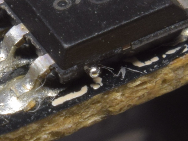
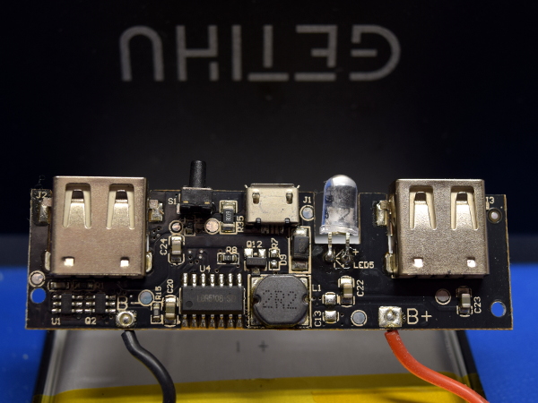
What do you not want to see in a power bank that you intend to carry in your pockets, luggage, or backpack? Loose metallic objects likely to cause the lithium cell to spontaneously dump its ~100kJ charge. Here, we have a small solder bead, which could break loose from the flux it is stuck into and find a new home where it could short out the cell.
Did the manufacturer use cotton balls to clean this board? Whatever it was, it left a lot of fibers stuck in flux that didn’t get cleaned out by other means.
MORE: QQC Q-Swap Power Bank Tear-Down
MORE: SilverStone PB06 USB Power Bank Tear-Down
Inverted Soldering
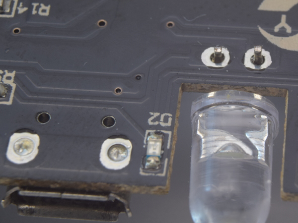
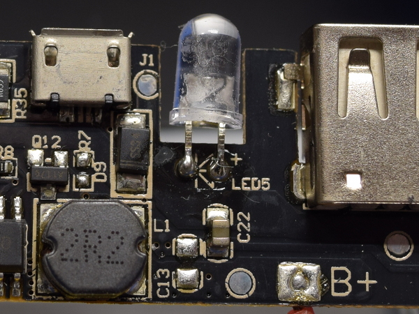
At first sight, you’d think that someone forgot to solder the 5mm LED’s leads from the lack of solder around them. For some strange reason, they were soldered from the top instead.
Does the micro-B port have mechanical tabs poking into the holes? If it does, they are too short to be visible at the bottom of the dimples formed by the solder’s surface tension when it reflowed within them.
MORE: QQC Q-Swap Power Bank Tear-Down
Get Tom's Hardware's best news and in-depth reviews, straight to your inbox.
MORE: SilverStone PB06 USB Power Bank Tear-Down
Unsightly Blob
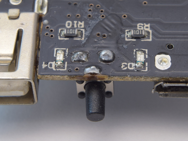
As far as blobs on a pad go, the one on the switch’s top-right lead is about as big as it can be before spilling solder around the pad. Also, with the switch so close to the board’s edge, I’d be a little worried about excessive force on the switch cracking the PCB and breaking a trace.
In one of my e-mails with GETIHU, a representative told me that many people complained about the switch protruding too much and frequently getting activated by accident. This was allegedly addressed by a revision, which hopefully backs the switch off by about 2mm from the edge.
MORE: QQC Q-Swap Power Bank Tear-Down
MORE: SilverStone PB06 USB Power Bank Tear-Down
Battery Protection
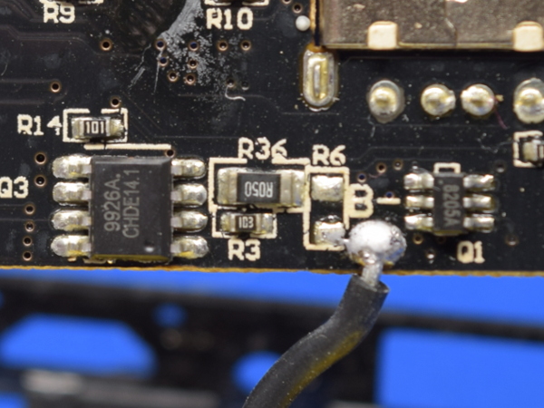
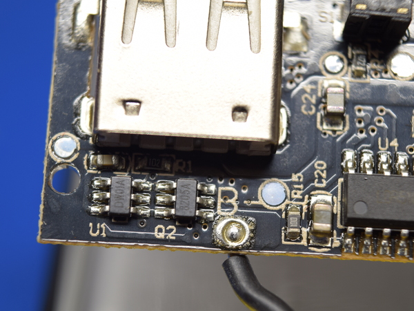
What are the two integrated circuits on this side of the board? The 9926A in SO-8 packaging on the left appears to be a dual independent N-channel 6.5A/20V MOSFET, while the 8205A in SOT-26 packaging to the right looks like a dual N-channel MOSFET with common drain rated at a slightly more modest 6A and the same voltage.
A typical battery protection circuit only requires one dual-N package to operate, which makes me wonder why there are two of them here. But wait: there’s more!
MORE: QQC Q-Swap Power Bank Tear-Down
MORE: SilverStone PB06 USB Power Bank Tear-Down
The Other Side
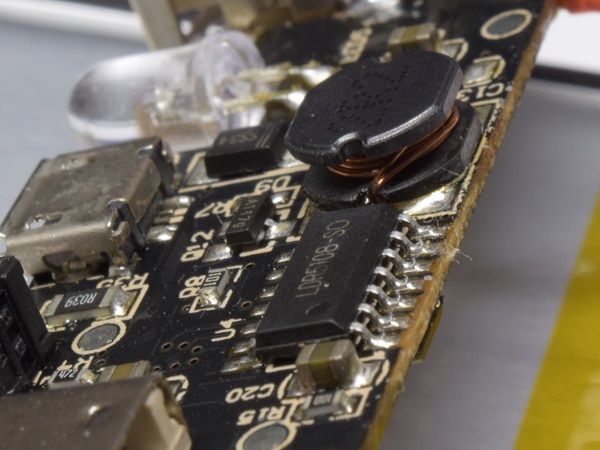
The top is quite a bit more crowded, with a Legendary LDR5108 special-purpose chip doing practically everything apart from cell protection, a 2.2µH inductor for the DC-DC boost converter, and a handful of additional support components. Overall soldering quality looks much better on this side, suggesting that everything except the 5mm LED was oven-reflowed.
MORE: QQC Q-Swap Power Bank Tear-Down
MORE: SilverStone PB06 USB Power Bank Tear-Down
Top-Side Soldering
Soldering on the top side looks far more typical of reflow soldering. All of the surface-mount components show a smooth fillet between board pads and component leads, and just the right amount of solder paste. This is particularly evident on the inductor pad and C20, near the bottom.
MORE: QQC Q-Swap Power Bank Tear-Down
MORE: SilverStone PB06 USB Power Bank Tear-Down
Top Blobs
Here’s what soldering component leads from the top looks like. With long leads pulling heat and solder away from the pad and into that bend, you end up with oddly shaped blobs.
Both battery pads show the same inverted doughnut shape visible to the left of B+. This is caused by solder pooling on top of the jumper wire's tip when it was soldered from the back, and the rest of the pad not getting hot enough to reflow with it.
Also of interest are the unpopulated pads for C13, to the inductor’s right. No input filter capacitor on a boost regulator may have some interesting effects on output waveforms.
MORE: QQC Q-Swap Power Bank Tear-Down
MORE: SilverStone PB06 USB Power Bank Tear-Down
The Real Battery Protection
If you have ever seen tear-downs of gadgets powered by a single rechargeable lithium cell, you won’t be surprised to find a DW01A next to a dual N-FET (the textbook combo). What’s a DW01, for those who don’t know? Possibly the most common single-cell over-charge and over-discharge protection IC in the business. All it does is enable the charging path’s MOSFET for as long as the cell voltage is below the over-charge threshold, doing likewise with the discharge MOSFET and the over-discharge threshold. This is an awfully simple, yet important responsibility when the goal is to prevent lithium cells from spontaneously combusting.
MORE: QQC Q-Swap Power Bank Tear-Down
MORE: SilverStone PB06 USB Power Bank Tear-Down
Why So Many FETs?
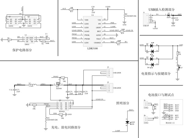
Seeing three FETs where I was only expecting one made me pull the LDR5108’s datasheet to explore further. Page nine of the PDF provides Legendary's reference design, which shows its DW01 implementation in the top-left corner using a pair of 8205 dual-N FETs in parallel for reduced losses. That's one mystery solved. The bottom-left schematic reveals that the LDR5108 is a synchronous rectification controller using one half of the 9926 dual-N FET as its boost converter switch and a separate FET for the synchronous rectifier, while the 9926’s other half turns off the outputs by disconnecting them from the low (ground) side.
GETIHU or its ODM went for a seemingly verbatim implementation of Legendary's reference design.
MORE: QQC Q-Swap Power Bank Tear-Down
MORE: SilverStone PB06 USB Power Bank Tear-Down
One Size Doesn’t Fit All
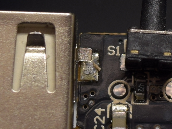
There are two problems here. First, the connector’s mechanical tab is half-way off of its pad’s location. Second, the clearly visible seam between the tab and solder puddle is usually a clear sign of a cold (weak) solder joint. A good joint wets the surfaces it adheres to, leaving no visible seam. Another possible issue is that, since the mechanical pads aren’t connected to anything, and aren’t staked to the board with solder-filled vias or slots, the only thing preventing them from ripping off the board is the glue between the three pads and PCB core.
What happened to throw the positioning off? Did GETIHU under-size or misplace its pads? We’ll never know.
MORE: QQC Q-Swap Power Bank Tear-Down
MORE: SilverStone PB06 USB Power Bank Tear-Down
-
dudmont Interesting. Doubt the OEM ever expected someone to get quite so "intimate" with their product. It's articles like this that keeps OEMs vaguely honest in this day and age. Who needs UL when when Toms will give a product a full rectal?Reply -
Daniel Sauvageau Reply
:)20716732 said:Who needs UL when when Toms will give a product a full rectal?
Just keep in mind that UL, CSA, VDE, etc. mainly deal with electrical, fire and mechanical safety issues, not misleading or fraudulent marketing or performance. Fraudulent claims is something for the consumer protection, advertising standards and other similar agencies to deal with. You could get the most blatant PoS falsely advertised gizmo you can conceive of UL-listed as long as it passes safety checks for whatever applicable UL categories you apply for. If your gizmo has power outlets on it, you can probably get it UL-listed for UL 1363 (relocatable power tap) regardless of how unsafe unrelated additional functions might be as the UL listing pertains exclusively to the power bar function and related aspects of the product. Secondary features such as built-in USB ports would be covered separately under something like UL/CSA 60950 which is specifically about information technology equipment safety. -
BaRoMeTrIc This is the problem with open trade. These products get into the U.S. from China via amazon, newegg, ebay... They slap fake UL stickers on there, fake specs. No one checks them out or holds them accountable. We need better regulation.Reply -
dudmont Reply20717076 said:This is the problem with open trade. These products get into the U.S. from China via amazon, newegg, ebay... They slap fake UL stickers on there, fake specs. No one checks them out or holds them accountable. We need better regulation.
Do you think someone working for uncle Sam would have done what Sauvageau did(and the answer is no, because someone from the electronics industry is already offering any competent engineer from Gov. who would checking stuff like this a job)? Call me a strong skeptic. Government, business, my neighbors, everyone but my own flesh and blood is to be trusted, but verified(and possibly not even trusted in the least). -
Daniel Sauvageau Reply
I haven't had one of those yet, so no first-hand comment on that but one of my friends who owns a few Anker accessories is eagerly waiting for me to get around to tearing into one and see if I'll find anything that might shake his confidence in the brand.20722606 said:any brands to recommend here, or just stick with Anker
Between power banks I've shown here so far though, the SilverStone PB01's track record for poorly soldered micro-B ports (two out of three, though I haven't opened the third one to check, only saying so because it hasn't failed me yet, unlike the 2nd unit whose micro-B was practically DOA) is very unfortunate and although the Q-Swap is neatly built, it is expensive compared to countless other 10Ah-class alternatives. The GETIHU may have been ok-ish for the price had it been advertised at its actual 8Ah. -
Gam3r01 Im using an Anker powercore 10k and Im liking it, but it sure would be great to see something this in depth on it.Reply -
icycool_q1 I love reading your tear-downs.Reply
These companies should start paying you to get their products right!
