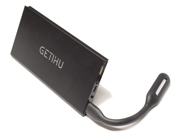
GETIHU PB-01 Power Bank Tear-Down
Wait, Three?
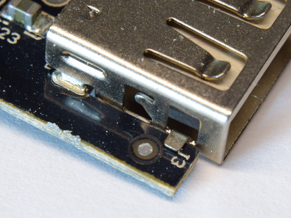
There are two connectors with two front mechanical tabs each. Shouldn’t that add up to four pads? Yes, but the second connector is missing a pad altogether due to the fiducial mark’s location. Having only one side of the connector correctly tacked down should be sufficient to prevent the port from wiggling and eventually breaking connections at the back. Unfortunately, there are none of those to be found in my sample.
MORE: QQC Q-Swap Power Bank Tear-Down
MORE: SilverStone PB06 USB Power Bank Tear-Down
Short Story
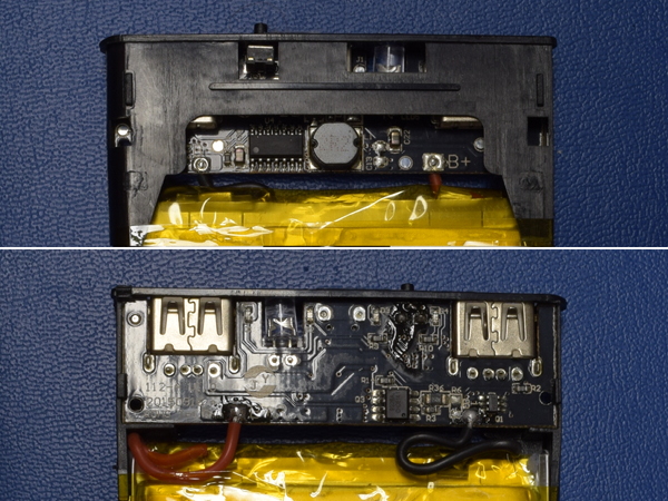
While re-assembling the power bank to re-take some photographs. I noticed something potentially dangerous that I initially missed: the lithium cell’s jumper wires connect to the board's unprotected back where their respective solder blobs could potentially short to the power bank’s aluminum housing if you apply enough pressure to it.
From the way the plastic shroud over the board's top side gives largely unimpeded access to the two battery pads, it looks like the jumpers were meant to be soldered after assembly on the inside, a safe distance away from the aluminum body.
MORE: QQC Q-Swap Power Bank Tear-Down
MORE: SilverStone PB06 USB Power Bank Tear-Down
Get Tom's Hardware's best news and in-depth reviews, straight to your inbox.
Dumb “Smart” Detection
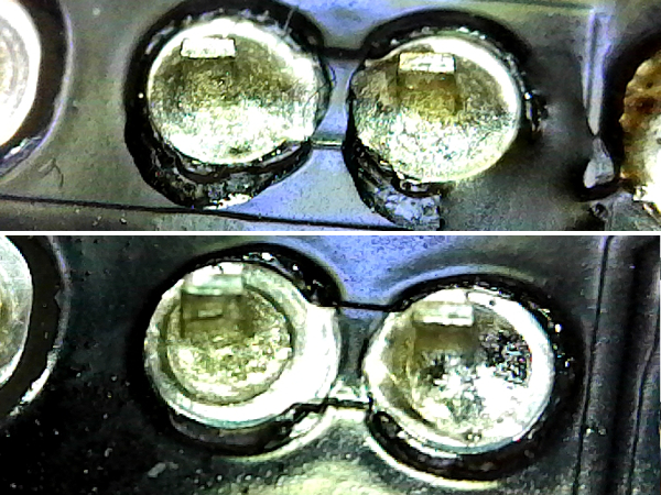
GETIHU’s manual claims that the PB-01 detects how much power attached devices need, but I didn't see a charging protocol detection chip on either side of the board to read data lines. Putting the data pins under a microscope shows that they are simply tied together. So much for smarts. The power bank's DC-DC converter simply provides whatever the load draws, as long as it is within its limits.
MORE: QQC Q-Swap Power Bank Tear-Down
MORE: SilverStone PB06 USB Power Bank Tear-Down
Output Waveform
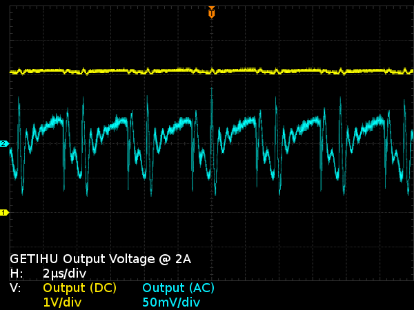
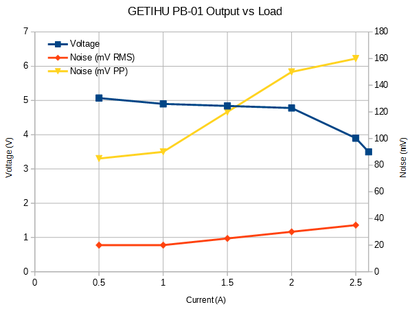
What does the output look like? From 500mA, where the output enters steady operation, until it enters overload at 2.1-2.5A (depending on cell charge), the output maintains roughly the same noise waveform, progressing from 85mVPP to 160mVPP mainly due to switching transient peaks. RMS noise is much milder at 35mV.
At a switching frequency of 250 kHz, I was expecting better output filtering than this.
MORE: QQC Q-Swap Power Bank Tear-Down
MORE: SilverStone PB06 USB Power Bank Tear-Down
Overload Waveform
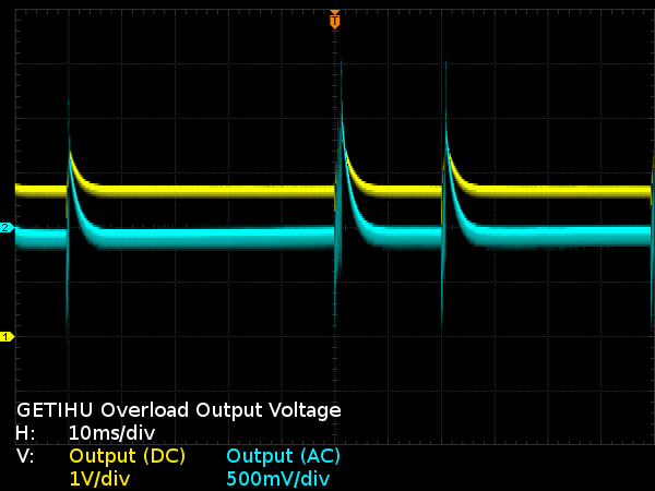
Once the regulator enters cut-off mode, presumably due to low cell voltage before hitting the over-current shutdown limit, the output voltage drops 0.4V below the cell’s voltage with sporadic peaks from the boost converter attempting to restart. This causes the cell voltage to droop, and the converter to shut down again.
I was expecting the power bank to simply shut down its output, rather than lingering one diode drop below cell voltage between converter restarts.
MORE: QQC Q-Swap Power Bank Tear-Down
MORE: SilverStone PB06 USB Power Bank Tear-Down
Output Performance
At 0.5A and 1A, the output quality is acceptable. Then, noise picks up starting from 1.5A. While 160mVPP may sound like a lot by PC power supply standards, the USB Battery Charging specification allows any amount of noise from 4.1V undershoots to 6V overshoots as long as the 250ms average is between 4.75V and 5.25V. By that standard, 160mVPP should be a non-issue for devices that follow the BC specifications.
Voltage does hold up quite well, starting at 5.04V until hitting 4.89V at 2A. Beyond that, it collapses from the boost circuit hitting its duty cycle limit until it outright shuts down at 2.5-2.6A, allowing straight cell voltage through.
MORE: QQC Q-Swap Power Bank Tear-Down
MORE: SilverStone PB06 USB Power Bank Tear-Down
Output Waveform With C13 Populated
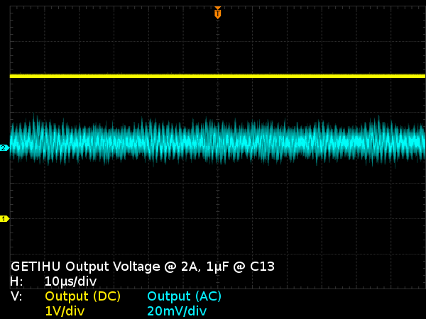
Remember that missing C13 I pointed out earlier? In previous tear-downs, whenever I attempted to improve an adapter or power bank by fitting something onto vacant capacitor pads, I was rewarded with little to no improvement. Not the case here: adding the capacitor reduced peak-to-peak noise at 2A output from 150mVPP to 26mVPP. That's much better than my expectations.
This is a perfect example of how shaving $0.01 off the bill of materials (BoM) can drastically affect a product’s performance.
MORE: QQC Q-Swap Power Bank Tear-Down
MORE: SilverStone PB06 USB Power Bank Tear-Down
Linear Thinking
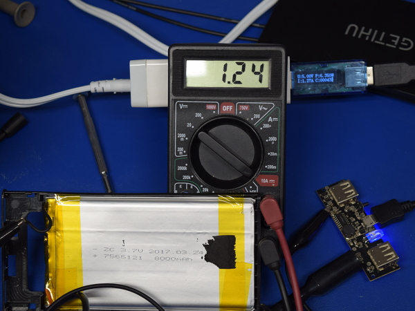
In the QQC and SilverStone power banks, cell charging is done by a dedicated switching regulator easily identified by the presence of separate inductors for input and output. To confirm that GETIHU’s design doesn’t use a clever bidirectional switching arrangement to share its inductor between charging and discharging, I measured current coming out of my UC-01 and current going into the cell. A 30mA difference between the two (1.27A vs 1.24A) can be attributed to GETIHU’s LEDs and DC-DC converter, which means we are definitely dealing with a linear regulator. That explains why it took a substantial 39Wh to charge a 29Wh cell.
MORE: QQC Q-Swap Power Bank Tear-Down
MORE: SilverStone PB06 USB Power Bank Tear-Down
Calling A Spade A Spade
After getting more intimate with GETIHU’s PB-01 than most people who weren’t involved in its design, I can say that the board’s manufacturing quality is lacking. I am displeased with its fake rating and peeved about seemingly being lied to about it. I wish I could call the real 8Ah cell a saving grace, but it is in no way, shape, or form an excuse for the clearly fake 10Ah marketing claim. Cell jumpers soldered on the exposed side of the PCB, where they could potentially short against the enclosure, are cause for concern. It also irks me that GETIHU sacrificed clean output to save a $0.01 part. Lastly, the lack of an efficient charging circuit is fair enough considering the price.
This is an unfortunately long laundry list of things to be disappointed about. For what it is worth, I do like the form factor, the overall construction, and the convenience of having a basic LED lamp built-in.
What do you think are the chances that GETIHU was honest when it told me it will investigate that 8Ah cell?
MORE: QQC Q-Swap Power Bank Tear-Down
MORE: SilverStone PB06 USB Power Bank Tear-Down
-
dudmont Interesting. Doubt the OEM ever expected someone to get quite so "intimate" with their product. It's articles like this that keeps OEMs vaguely honest in this day and age. Who needs UL when when Toms will give a product a full rectal?Reply -
Daniel Sauvageau Reply
:)20716732 said:Who needs UL when when Toms will give a product a full rectal?
Just keep in mind that UL, CSA, VDE, etc. mainly deal with electrical, fire and mechanical safety issues, not misleading or fraudulent marketing or performance. Fraudulent claims is something for the consumer protection, advertising standards and other similar agencies to deal with. You could get the most blatant PoS falsely advertised gizmo you can conceive of UL-listed as long as it passes safety checks for whatever applicable UL categories you apply for. If your gizmo has power outlets on it, you can probably get it UL-listed for UL 1363 (relocatable power tap) regardless of how unsafe unrelated additional functions might be as the UL listing pertains exclusively to the power bar function and related aspects of the product. Secondary features such as built-in USB ports would be covered separately under something like UL/CSA 60950 which is specifically about information technology equipment safety. -
BaRoMeTrIc This is the problem with open trade. These products get into the U.S. from China via amazon, newegg, ebay... They slap fake UL stickers on there, fake specs. No one checks them out or holds them accountable. We need better regulation.Reply -
dudmont Reply20717076 said:This is the problem with open trade. These products get into the U.S. from China via amazon, newegg, ebay... They slap fake UL stickers on there, fake specs. No one checks them out or holds them accountable. We need better regulation.
Do you think someone working for uncle Sam would have done what Sauvageau did(and the answer is no, because someone from the electronics industry is already offering any competent engineer from Gov. who would checking stuff like this a job)? Call me a strong skeptic. Government, business, my neighbors, everyone but my own flesh and blood is to be trusted, but verified(and possibly not even trusted in the least). -
Daniel Sauvageau Reply
I haven't had one of those yet, so no first-hand comment on that but one of my friends who owns a few Anker accessories is eagerly waiting for me to get around to tearing into one and see if I'll find anything that might shake his confidence in the brand.20722606 said:any brands to recommend here, or just stick with Anker
Between power banks I've shown here so far though, the SilverStone PB01's track record for poorly soldered micro-B ports (two out of three, though I haven't opened the third one to check, only saying so because it hasn't failed me yet, unlike the 2nd unit whose micro-B was practically DOA) is very unfortunate and although the Q-Swap is neatly built, it is expensive compared to countless other 10Ah-class alternatives. The GETIHU may have been ok-ish for the price had it been advertised at its actual 8Ah. -
Gam3r01 Im using an Anker powercore 10k and Im liking it, but it sure would be great to see something this in depth on it.Reply -
icycool_q1 I love reading your tear-downs.Reply
These companies should start paying you to get their products right!
