V3 Voltair V3TEC120-FC01 CPU TEC Cooler Review
V3 Components claims it can deliver innovative technologies to rival the performance of liquid cooling. We test these claims on an overclocked Haswell-E.
Why you can trust Tom's Hardware
Building With The V3 Voltair
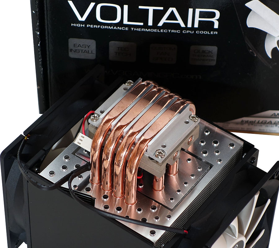
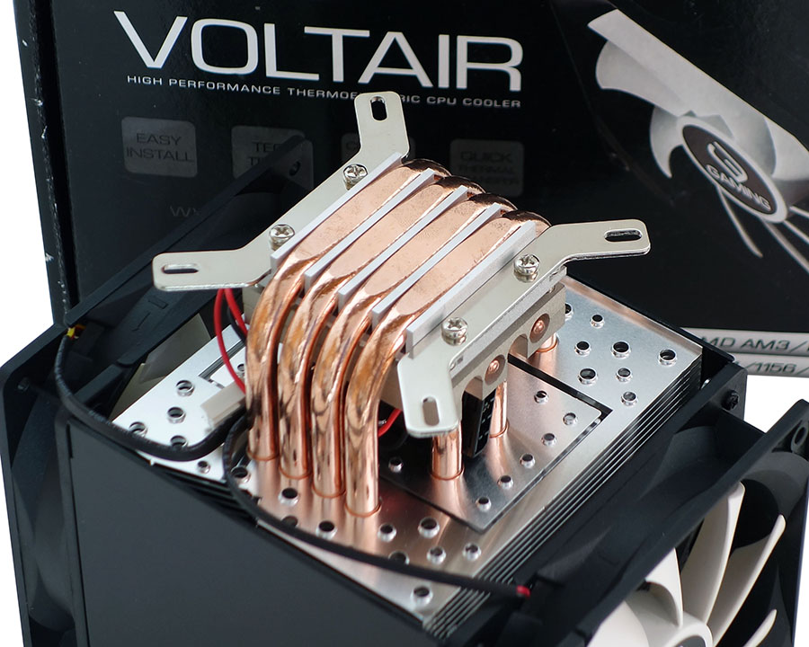
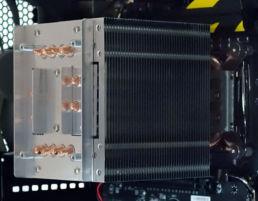
Understanding that the top side of the TEC element is hot, and the bottom cold, a quick look underneath shows that the Voltair has two separate heatsinks, an inner sink to cool the hot side and an outer sink to warm cold side. This might seem a little counter-intuitive, but it does appear to be an effective way to reduce the condensation problem. The cold side should never be more than slightly cooler than the air inside the case. And, just to make sure that those outer heat pipes make good contact with the CPU, they’re flattened, machined, and polished.
Beyond basic condensation, the two-part sink also addresses a second potential hazard of TEC coolers. Element failure can open or short the circuit, causing it to either quit transferring heat or worse, get hot on both sides. In the past, liquid cooling gurus would sometimes place a TEC element between a water block and CPU and assume the risk of a burned processor if the TEC failed. By placing a second set of heat pipes between the TEC element and CPU heat spreader, V3 Component has reduced the amount of heat that would get from a shorted-out TEC to the CPU. In other words, if the cooler ever fails, a normally functioning PC should have enough time to detect the heat problem and shut down. The system could potentially remain running off the outer sink alone in the more-likely event of an open circuit, though the reduced cooling capacity could cause an overclocked system to crash.
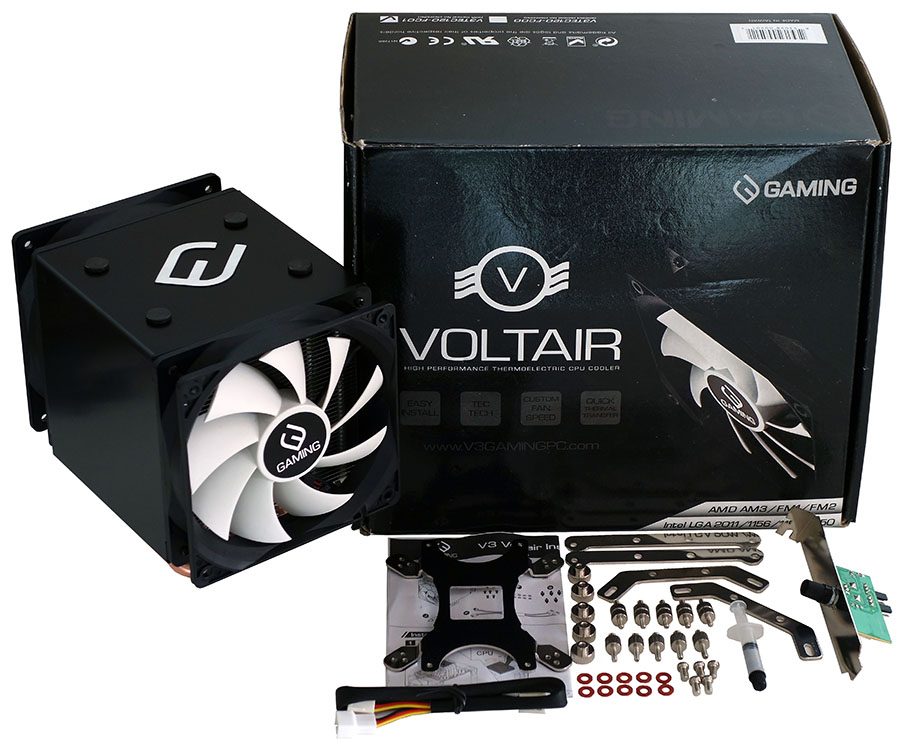
Two sets of base brackets allow the Voltair TEC CPU cooler to fit Intel’s square LGA and AMD’s rectangular socket mounting patterns. We installed the Intel version.
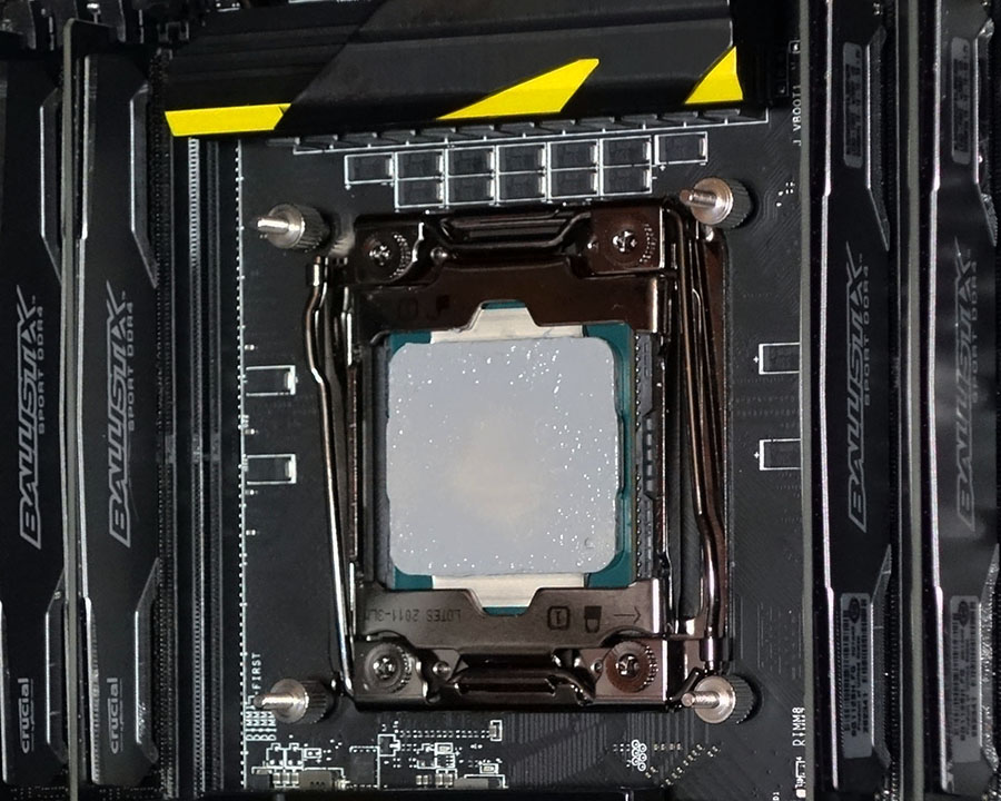
Two sets of standoffs are threaded to fit either LGA 2011 (v3) brackets or the V3-supplied support plate. Those who need the support plate must add it to the back of the board, behind the socket.
The cooler then threads onto the standoffs. V3 Components makes this a little easier by screwing the vans onto the black heat sink shroud, where the black things that looked like caps in previous photos were actually thumb screws.
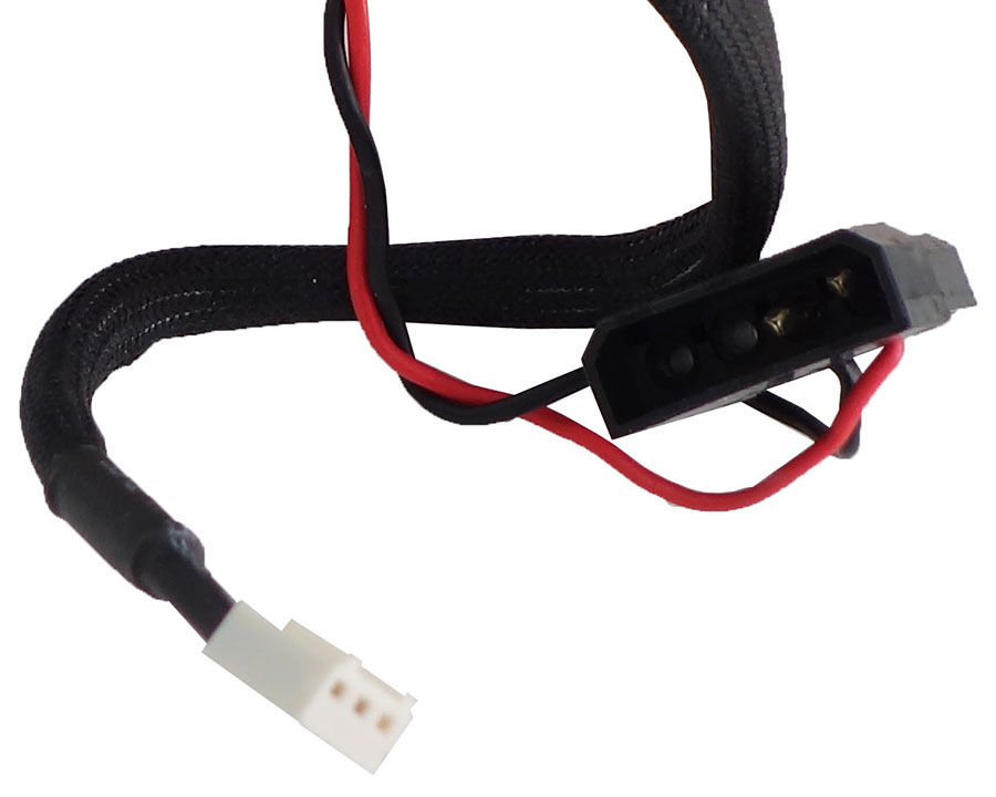
The TEC uses two power pins from an old drive power connector, while the fans are both spliced together to occupy a single 3-pin-fan header.
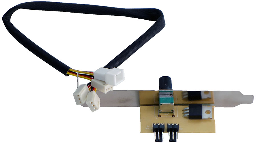
A potentiometer controls fan speed via voltage, within a range of around 940 to 1750 RPM. It replaces any of the case’s empty expansion slot brackets.
Get Tom's Hardware's best news and in-depth reviews, straight to your inbox.
The fan shroud can now be slipped over the heat sink and secured with thumb screws, and its fans plugged into the fan controller.
Alternatively, builders who prefer thermally-referenced firmware fan control could plug the fans into the motherboard instead. The important thing to note here is that 3-pin fans require voltage-based speed control, rather than relying on the PWM signal. Some motherboards support voltage-based control, others don’t, and many support this older method on some headers but not others.
Current page: Building With The V3 Voltair
Prev Page Technical Specifications Next Page How We Tested-
ingtar33 surprise surprise, an undersized air tower can't cool the Peltier (TEC) unit they attached it to.Reply
I think the only thing surprising is it even managed to keep up at all with those "real" cpu coolers. The problem with using Peltier based cooling is typically if you want to cool 80W of power you need to be able to disperse around 160W-240W of heat energy; it's clear they went with an under powered peltier to avoid condensation, but of course that defeats the whole purpose to one as well; because then you end up with a cooler not strong enough to cool on one side and too hot to cool on the other (with the undersized heatsink)
really the only sensible use for a peltier in a computer would be through some sort of heat exchange method, like paired with a large custom water loop, and lots of radiator space, while at the same time, insulating the connection point and BACK OF THE MOTHERBOARD to prevent condensation damage to your system.
throw in the fact that Peltier or TEC cooling wears out over time, and this just looks like a terrible product. too little radiator space, too little voltage going into the Peltier, too much noise generated by the undersized fans, not enough cooling ability... just a mediocre product -
PaulBags Several times now I've read in a tom's review references to past experience with big coolers coming loose and/or damaging boards. Would you mind linking us to those examples?Reply -
atheus ReplySeveral times now I've read in a tom's review references to past experience with big coolers coming loose and/or damaging boards. Would you mind linking us to those examples?
I know this is not what you're asking for, but after building a computer for a friend and shipping it across the country I'm fairly convinced that at least when designing a computer that you intend to ship it's probably best to use a closed loop liquid cooler. I just had a Hyper 212 EVO mounted on an ASUS Z97 GRYPHON, and evidently the USPS dropped it from a substantial height, causing the heat sink to break free and damage the CPU, plus the graphics card tore the PCIE slot in half. I think from now on any time I ship a computer that has a big air cooler, I'll remove the cooler (and graphics cards, if any) and pack them separately. For someone who doesn't have the skills to mount a CPU cooler, I'll just have to stick to closed loop water.
USPS eventually paid for the damaged computer ($1300), but it took over a month to get the check, and there were tons of hoops she had to jump through. For a while it was even starting to look like they weren't going to pay up. Not worth the headache. From now on I'll make sure any computer I ship is ready to be dropped from an airplane at 500 MPH without a chute, as much as possible. -
Crashman Reply
Linking you? You do know that there's a real world out there, where photos of damaged systems that we packed could be evidence in a lawsuit. And I don't go after the suppliers of prebuilt systems when theirs arrive damaged either, because that feels like adding insult to financial injury. The only ONLINE proof that any of this has happened is in restricted-access servers, though I can't stop anyone from hacking my email ;)16106597 said:Several times now I've read in a tom's review references to past experience with big coolers coming loose and/or damaging boards. Would you mind linking us to those examples?
Most things in this world don't happen online. I think it's nice that someone can tell me "this part got wrecked in shipping" and I can say "send it to me, I'll evaluate it before I replace it". I realize that its unbelievable to some that this still happens in the age of snapchat...
As for the less spectacular (warped board) failures, they're mentioned in an SBM article where the motherboard was a Z77 Extreme4.
-
OcelotRex Reply16106917 said:
Linking you? You do know that there's a real world out there, where photos of damaged systems that we packed could be evidence in a lawsuit. And I don't go after the suppliers of prebuilt systems when theirs arrive damaged either, because that feels like adding insult to financial injury. The only ONLINE proof that any of this has happened is in restricted-access servers, though I can't stop anyone from hacking my email ;)16106597 said:Several times now I've read in a tom's review references to past experience with big coolers coming loose and/or damaging boards. Would you mind linking us to those examples?
Most things in this world don't happen online. I think it's nice that someone can tell me "this part got wrecked in shipping" and I can say "send it to me, I'll evaluate it before I replace it". I realize that its unbelievable to some that this still happens in the age of snapchat...
As for the less spectacular (warped board) failures, they're mentioned in an SBM article where the motherboard was a Z77 Extreme4.
I am not very sure you sufficiently answered his concerns with hypothetical situations that you cannot prove/disprove. I think that the OP was looking for something concrete since an occurrence has been referenced (in their experience) a few times on the same site.
I had the same concern when purchasing a larger air cooler - I had settled on the Cooler master 212 on a non-overclocked build to keep it cool/quiet but had been building with smaller, older Zalman fans. To alleiviate those concerns I when with a Silverstone case that inverted the motherboard and added an adjustable stand for the heatsink to take the vertical strain off the MB:
But to your point shipping a PC is a whole other issue as you cannot control the orientation or handling of the item throughout the process so I can see how bending/warping/snapping could happen. for such large coolers the safest bet would be to disassemble the heavy parts prior to shipping. -
atheus Reply
Here you go. If it's computer snuff you want:16106597 said:Several times now I've read in a tom's review references to past experience with big coolers coming loose and/or damaging boards. Would you mind linking us to those examples?
Yeah, that CPU fan is spinning. -
ubercake At the beginning of the article I was excited about the technology.Reply
At the end of the article, I was sad that it couldn't really compete (but I did feel well informed!). -
Blueberries Even when they made these twice the size it wasn't enough. Vapor chambers are the future of heat-sink design, not this.Reply -
Crashman Reply
I'm not trying to prove or disprove a hypothetical situation. I'm testifying to real-world occurrences. Does anyone really need the testimony of Chris and Don to prove that things he or she knows can happen, did happen?16107269 said:I am not very sure you sufficiently answered his concerns with hypothetical situations that you cannot prove/disprove.
This one shouldn't be all that controversial. It's like if I told you about that time I went to Florida and my wife fed squirrels at the park from her hand, and rather than argue about the behavior of the squirrels you began arguing about whether I'd ever been to Florida.
If I said it rained yesterday you'd probably believe it. On the other hand, if I said it didn't rain you'd probably believe that. Both solutions are equally possible, one solution is actual and the other potentially "hypothetical" (IF it hadn't rained...). The reason you'd have believed either one is that neither option is particularly controversial, and I don't have anything to gain by lying.
-
kristi_metal I have only one problem with this cooler: the "space" between the heatpipes that form the base of the radiator. The heat is only absorbed by the heatpipes, but the aluminium strips just keep the heat there, it is not that efficient in removing heat from the CPU.Reply
