APC BX1000 Click-of-Death Repair
Following My Own Advice
When people ask me how to troubleshoot a device they aren’t intimately familiar with, my first recommendation is to start from the power supply. This is common wisdom: if you have garbage power going into a system, you will inevitably encounter garbage output, making it impossible to troubleshoot anything else until you resolve the power problems. I have ignored my own advice in previous stories both out of curiosity and for educational purposes. This time around, though, I am going for efficiency and will drill straight down the power supply chain until I find something that is broken. I’ll worry about other possible failures if I fail to find anything related to power along the way.
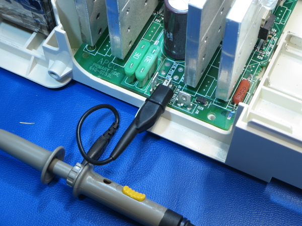
Before poking around the UPS, I verified that the low-voltage side was indeed isolated from mains under all operating modes by watching battery negative voltage on the scope with a 1000Ω resistor pulling it to ground. Confirming that battery negative remained at ground potential allowed me to put a jumper (in the form of a spare oscilloscope probe’s alligator clip) from negative to ground. This spared me the hassle of finding ground points close enough to points of interest.
One downside is that oscilloscope measurements may contain significant common-mode noise. However, having some common-mode noise in non-critical measurements is preferable to having a ground wire or spring where it may potentially short out to 120V mains or battery positive. If I find places where I need to eliminate as much common-mode noise as possible to make the call between common-noise, a bad cap, and whatever else, I can always come back to those spots with a ground spring attachment later. It makes no sense to risk it until I have specific reasons to do so.
First Stop: 24VDC Charging Supply
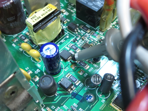
The BX1000’s power supply has one power supply rail, if we ignore the auxiliary winding on its primary side. The main switcher is a TOPSwitch flyback controller with built-in FET, and its output filter is a 390µF 35V Chemi-Con capacitor that should be perfectly adequate for the task. Its output voltage is 27.6V, which sits comfortably within the realm of what you would expect the float-charging voltage of a 24V VRLA battery pack to be, so no issue there.
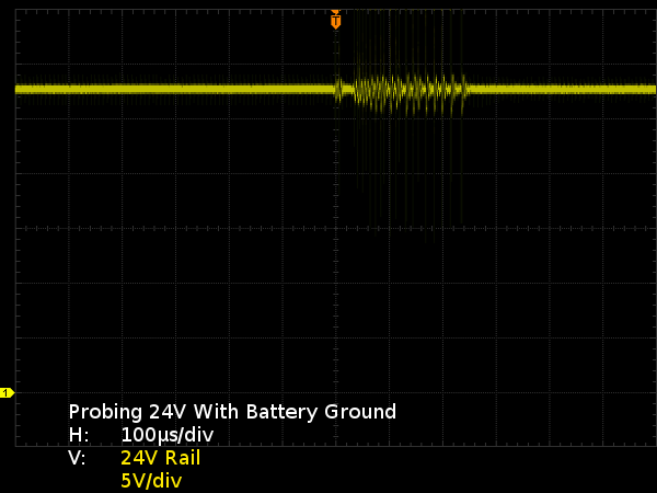
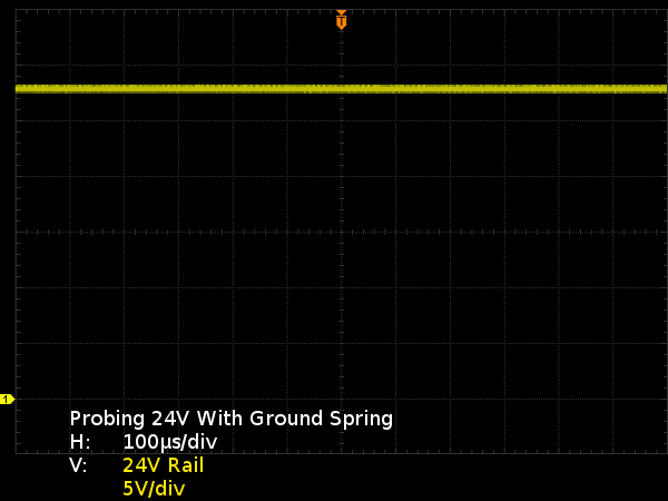
On the oscilloscope, the 24V rail looks perfectly fine except for common-mode noise bursts. Since there are plenty of large ground and positive pads in the area, I redid the oscilloscope measurement using a ground spring attachment to show how common-mode noise can vary depending on where you measure. As you can see, bringing ground closer to the measurement point practically eliminates common-mode noise, and what may have initially looked like a questionable capacitor turns out to be fine.
Unfortunately, I remembered common-mode being an issue only after I had already swapped the capacitor and found out that the results didn't change. This capacitor and voltage rail are good, so it's time to move on to the next logical stop.
Second Stop: 12V Linear Regulator
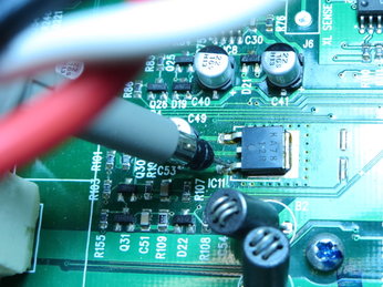
This KA7812 linear regulator takes the 20-28V battery or power supply voltage and drops it to 12V. Did the warmest chip on the board die from running hot enough to discolor the PCB’s solder mask across its heat sink ground plane on both sides of the board? If you look at my tear-down pictures, some of them clearly show how extensive the affected area is on both sides.
Get Tom's Hardware's best news and in-depth reviews, straight to your inbox.
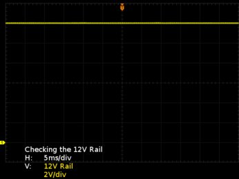
If it didn’t die during the first 10 years, I doubt it would do so now. But since I am already in there with my test equipment, it takes only seconds to turn that suspicion into a known quantity. My multimeter says it is still putting out 12V as expected, and my oscilloscope confirms it still looks squeaky-clean. This means that the fault must be further downstream. The last suspect on my list is the power supply rail running the UPS’ micro-controller.
Third Stop: 5V Logic Supply
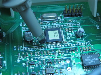
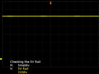
Initially, I could not find where the micro-controller voltage came from. By probing the pads (conveniently exposed in the form of a dual DIP-QFP footprint), I determined that its supply voltage was 5.2V, and again, my oscilloscope told me the rail should be clean enough to run the controller. Whatever is causing the UPS to have trouble turning on must come from somewhere else, and I have run out of obvious supply rails to check. It's time to dig deeper from another angle.
MORE: APC BR1000G Tear-Down
MORE: APC BN650M1-CA Tear-Down
MORE: APC BGE90M-CA Tear-Down
Current page: Following My Own Advice
Prev Page Revisiting The BX1000 Next Page From Input To Output-
Zaxx420 'Now on to the next one: why did the capacitor fail in the first place?'Reply
That's one aspect that sooo many folks never consider or can't be bothered to investigate. Just like a fuse that keeps blowing...there is something that's causing it to blow...even if it lasts a while before blowing. Even worse is when they decide to bridge it with a piece of wire or wrap the blown (glass) fuse with aluminum foil. Now I'm guilty as well but ONLY long enuff to get myself out of a jam...like being stranded on the side of the road or something. Just never do it with a high current load or if it's blowing the instant you turn it on...and never with a sensitive/expensive critical component like the ignition ECU of your self semi-restored muscle car project...don't ask. -
Daniel Sauvageau Reply
The repair is already done and I'm not set up for recording - don't even own a video camera or webcam. Even if I did own one, I'm no good with talking and working at the same time. Also, if I posted repairs on YouTube, I wouldn't be able to post them on THG since THG is paying me for exclusive publication.18828366 said:When you do fix it, can you YouTube it?
Too much credit :) This is basic troubleshooting, anyone going through electronics tech training should be able to do as before graduation.18830162 said:You are so smart.
-
jcamilo70 I have a 2005 RS1200 that died on me, making clicking sound constantly, and only turning on directly into battery mode.Reply
Where did you manage to get the replacement pieces? Where could I find the micro-controller for this unit or how should I identify its part number in order to look for it? -
Daniel Sauvageau Reply
The only part I needed to replace here was that single capacitor. Where did I get the capacitor from? It was just one of many leftover parts I've accumulated either from ordering more parts than necessary for past repairs/projects, or parts I had ordered for potential future projects to pad orders for free S&H. I may have over $2000 worth of parts in my spare parts and samples boxes.18830308 said:I have a 2005 RS1200 that died on me, making clicking sound constantly, and only turning on directly into battery mode.
Where did you manage to get the replacement pieces? Where could I find the micro-controller for this unit or how should I identify its part number in order to look for it?
For the micro-controller, I didn't touch it. Even if I had wanted to replace it, they can only be ordered blank from parts distributors (or pre-programmed with your own firmware for large enough orders or distributors that offer such a service for an additional fee) and those would be no good without the correct firmware to put on them. If the controller died, it is game over unless you can find a donor UPS based on the same PCB. -
powernod This example showed us the importance of high quality caps to be used in such critical components such as a UPS/PSU. A single cap-failure (*from the many a UPS uses) and caused total malfunction of the UPS !!Reply
P.S. This review has also shown us the importance/need for UPSs reviews. Since PSUs are being thoroughly reviewed for many years, i don't understand why UPSs shouldn't be reviewed as well!! A PSU's proper operation is in consequence with the proper operation of the hardware that "feeds" a PSU (*UPS)
P.S.2 : Great article by the way!!
