How To Build A $2,500 Gaming PC
Installing The Components
Lay the case on its right side (mind the hanging cables in the drive chamber as you set it down) so that the motherboard tray is upright. Grab the motherboard’s I/O backplate and install it to the case by pressing firmly and evenly along its edges from inside the main chamber of the chassis.
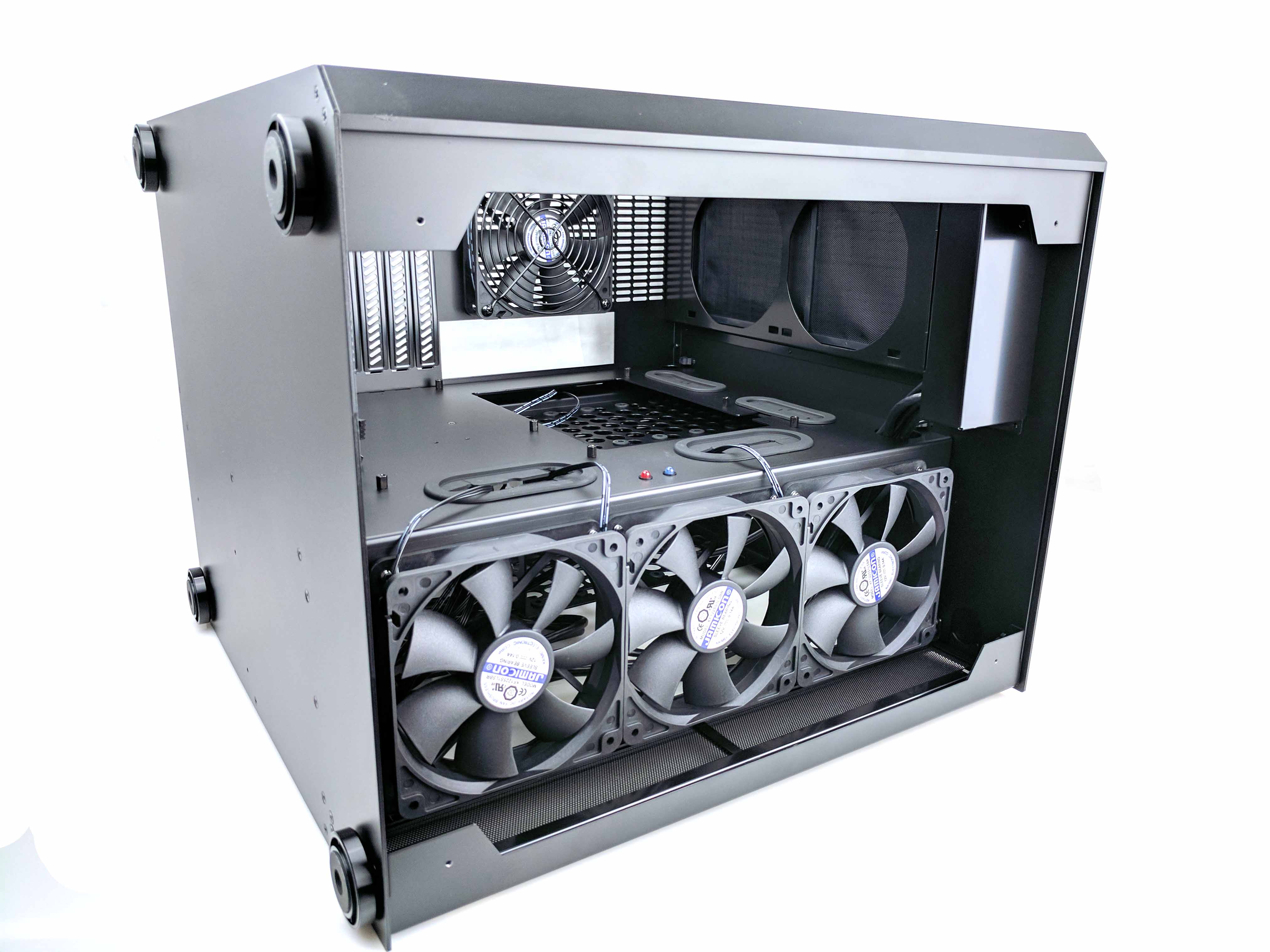
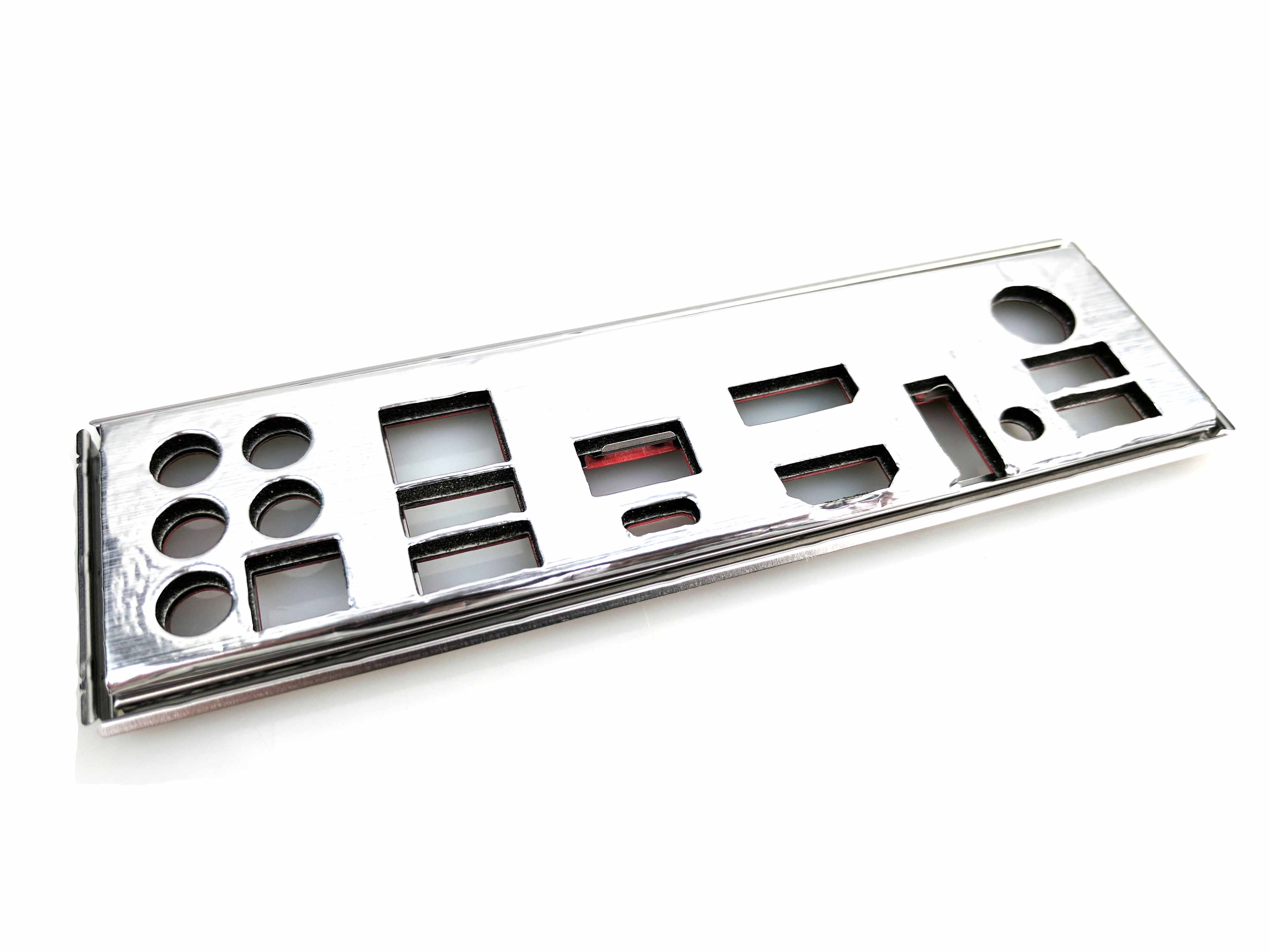
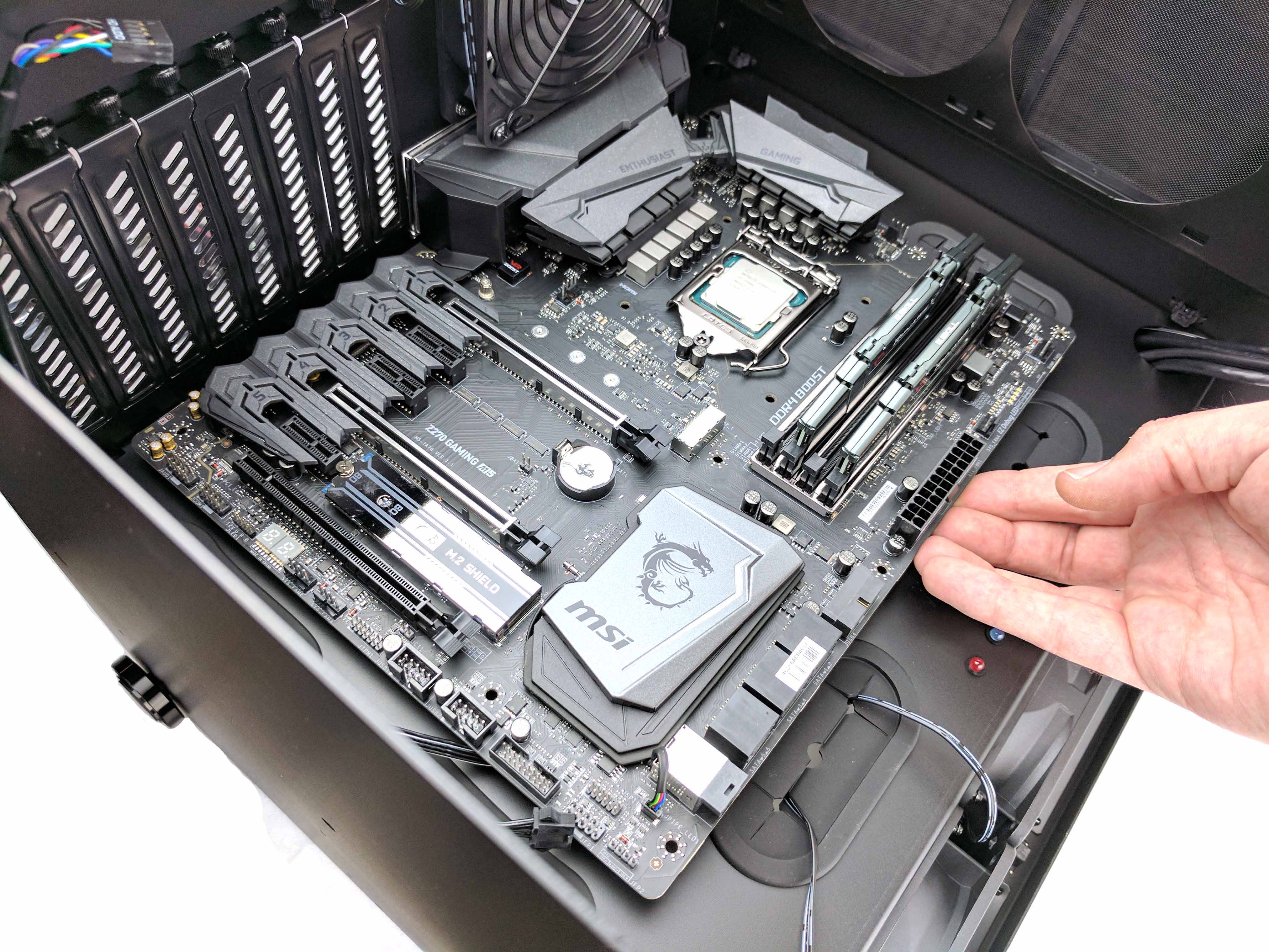
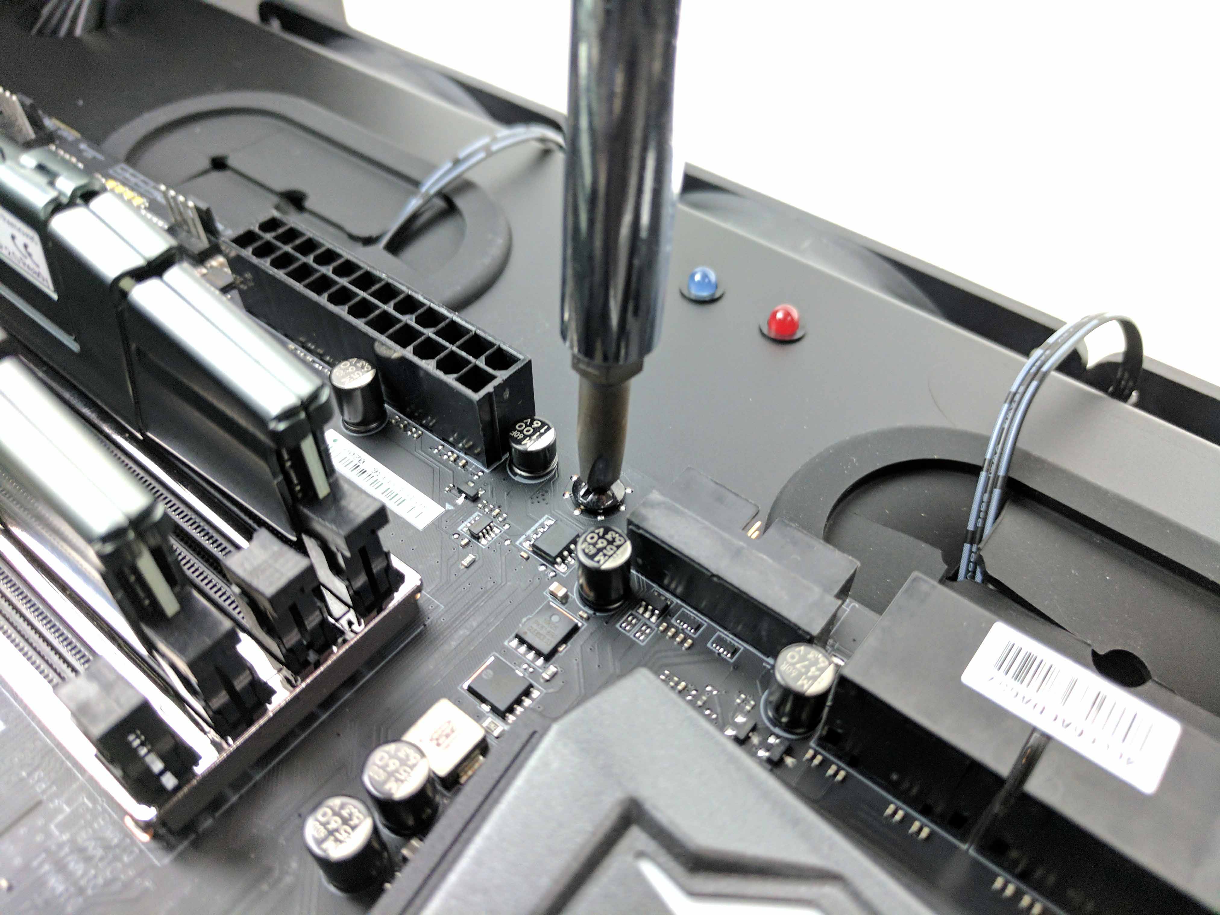
Lower the motherboard into position (mind the RGB LED extensions and audio cables as you do so), lining up the holes to posts and the rear I/O backplate with its ports (see 3rd picture in the album above). Screw in the motherboard using the fat-headed, thick-threaded Phillips-head screws (nine of them) to secure it to the case.
Connect the HD audio cable (which is resting at the bottom of the main chamber) to the motherboard, and feed the excess back into the drive chamber (from whence it came). As you run cables, keep in mind that you want the main chamber of the chassis to look as clean as possible.
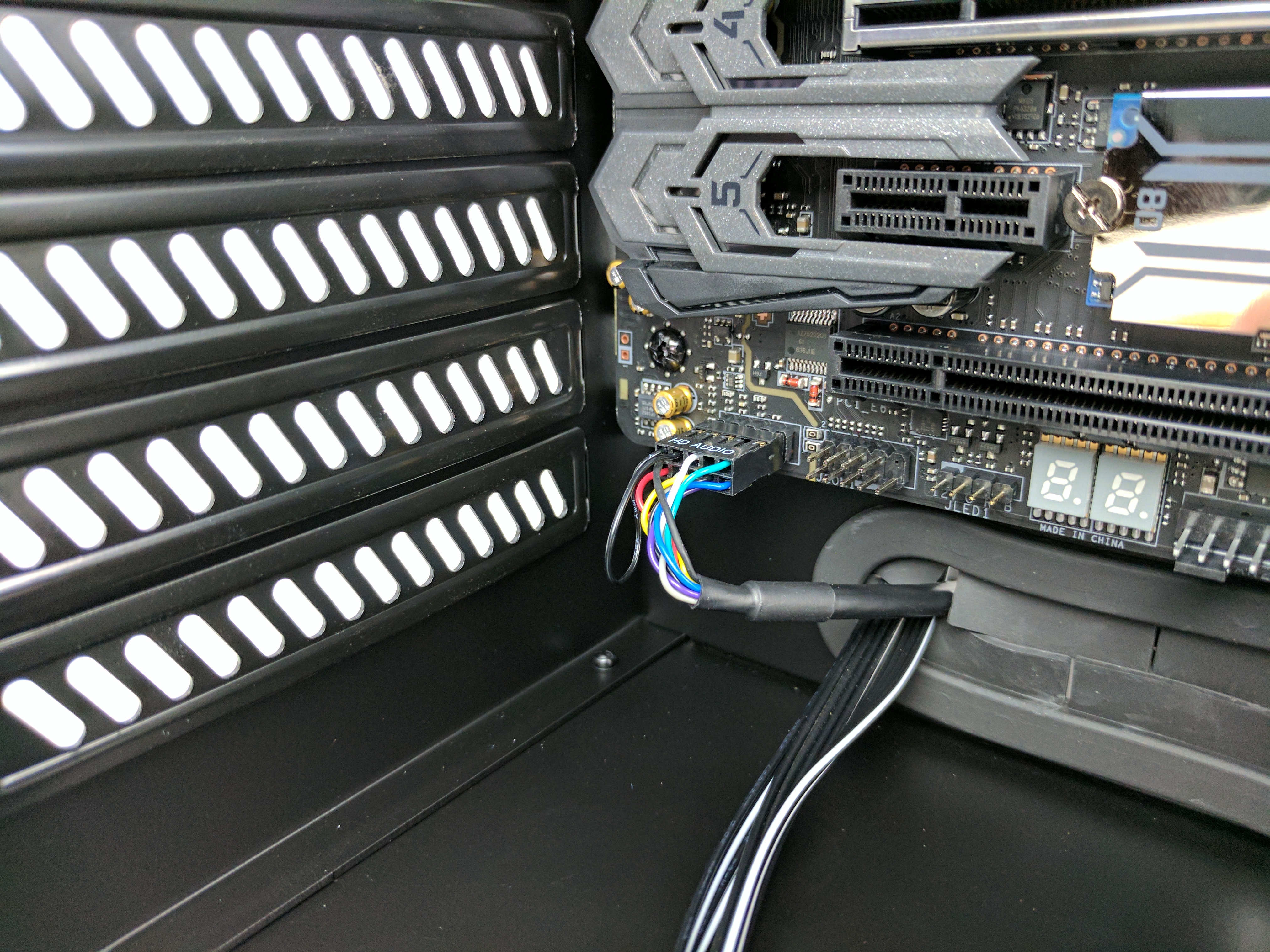
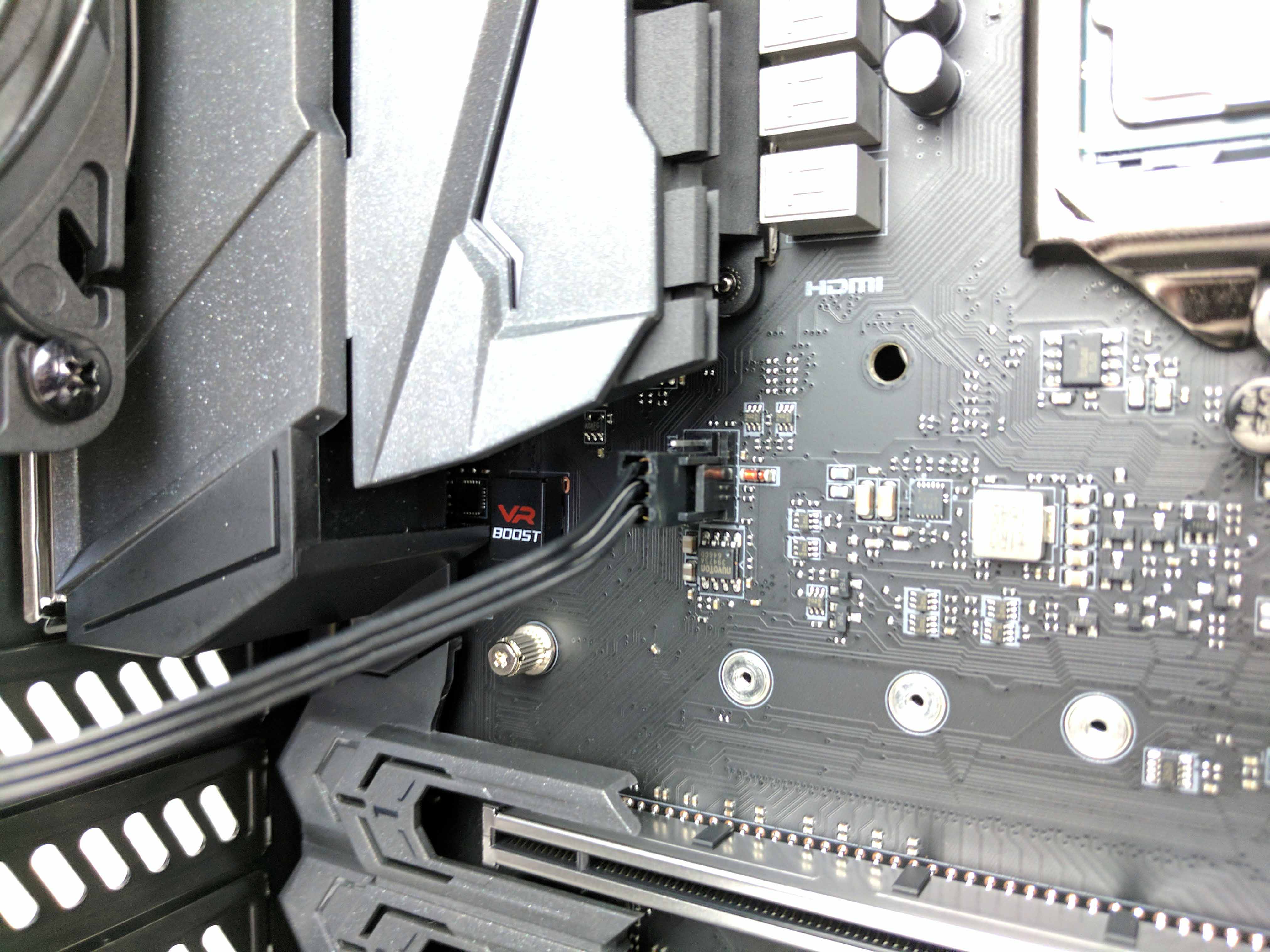
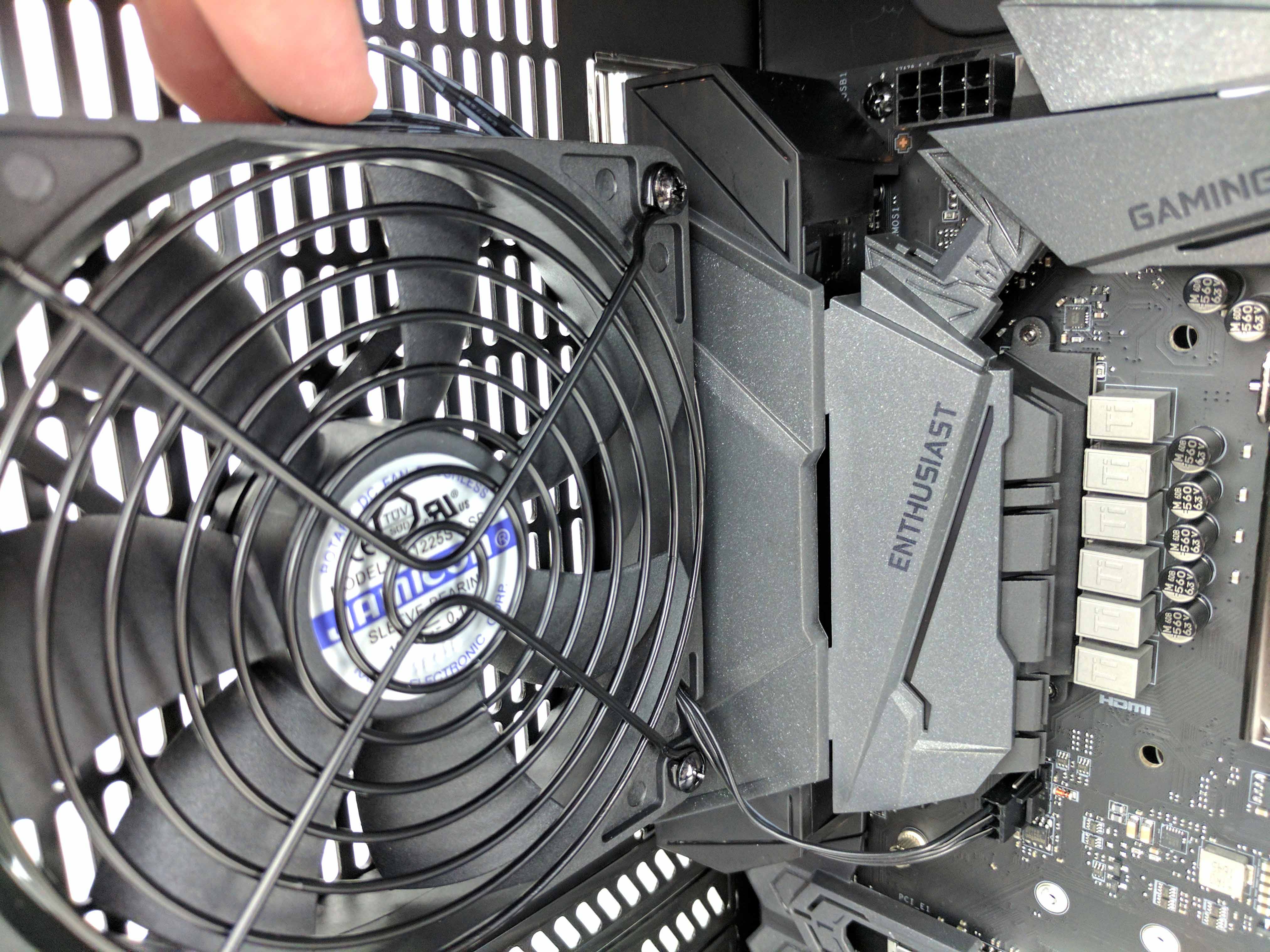
In that spirit, untie the main chamber’s rear fan cable. Feed it through the gap between the fan and plastic motherboard shroud (loop the wire first) and send it down to the notch in the fan frame. Pull the plug out of that hook and connect it to the motherboard’s SYS_FAN1 header. Tuck the excess between the fan and motherboard, then tuck the loop into the same gap between the motherboard and fan to give it a clean look.
Feed the front panel I/O wires through the hole at the bottom left of the drive chamber (1st picture in the album below). Attach the leads to the appropriate pins (refer to your manual or read the labels on the board) on the header, located next to the USB 3.0 pins on the motherboard. Once all the leads are connected, run the excess back through the hole and loop the cable together, cleaning it up with a white tie wrap.
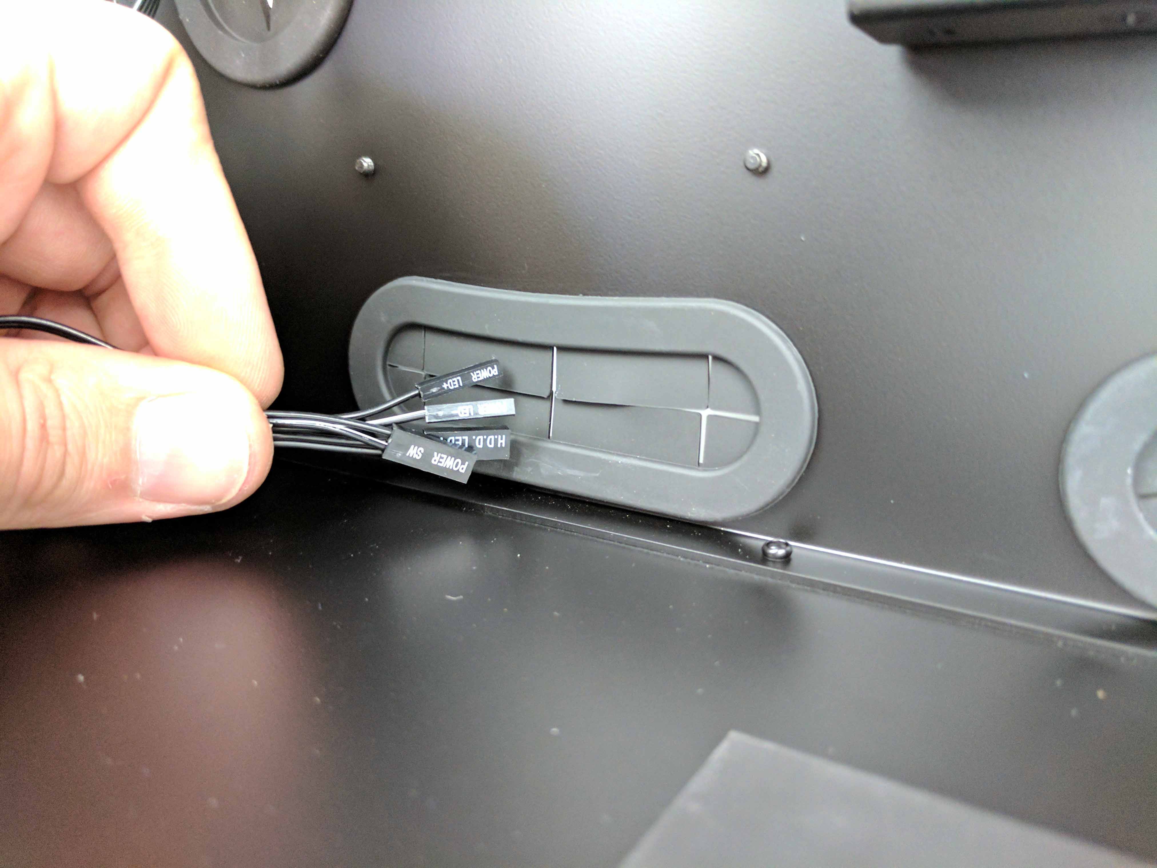
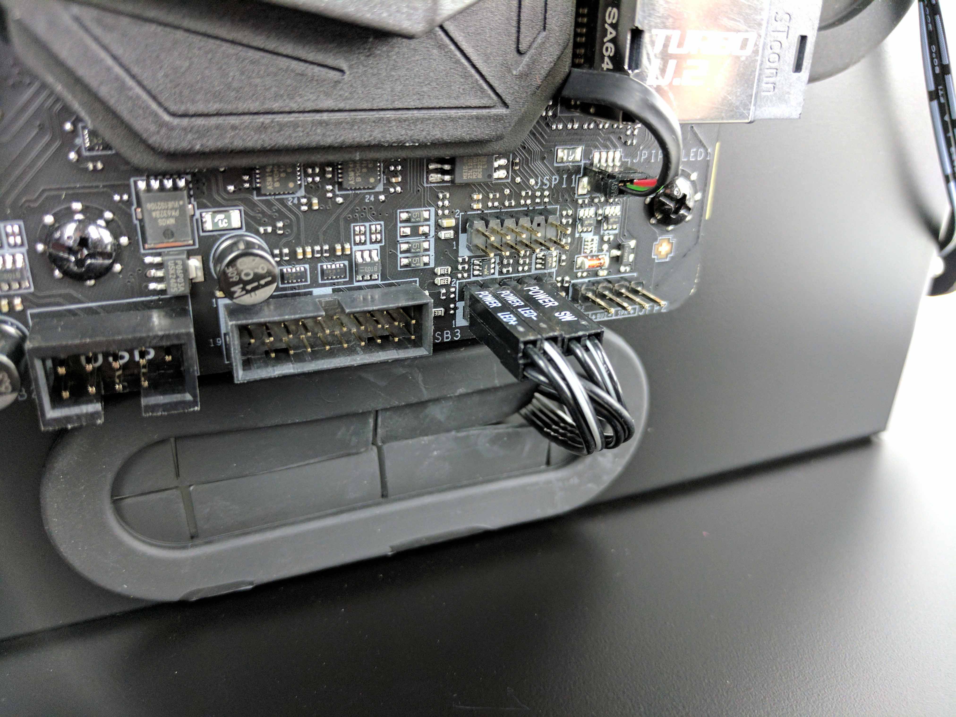
The case also sports two USB 3.0 front panel cables. Run one of the cables into the same hole as the front panel I/O wires and connect it to the USB 3.0 header on the motherboard (pictures 2 and 3 in the album below). Bend the cable so that there is no tension on the header. Feed the excess wiring back into the drive chamber of the case, laying it along the bottom of the case with the front panel I/O cables.
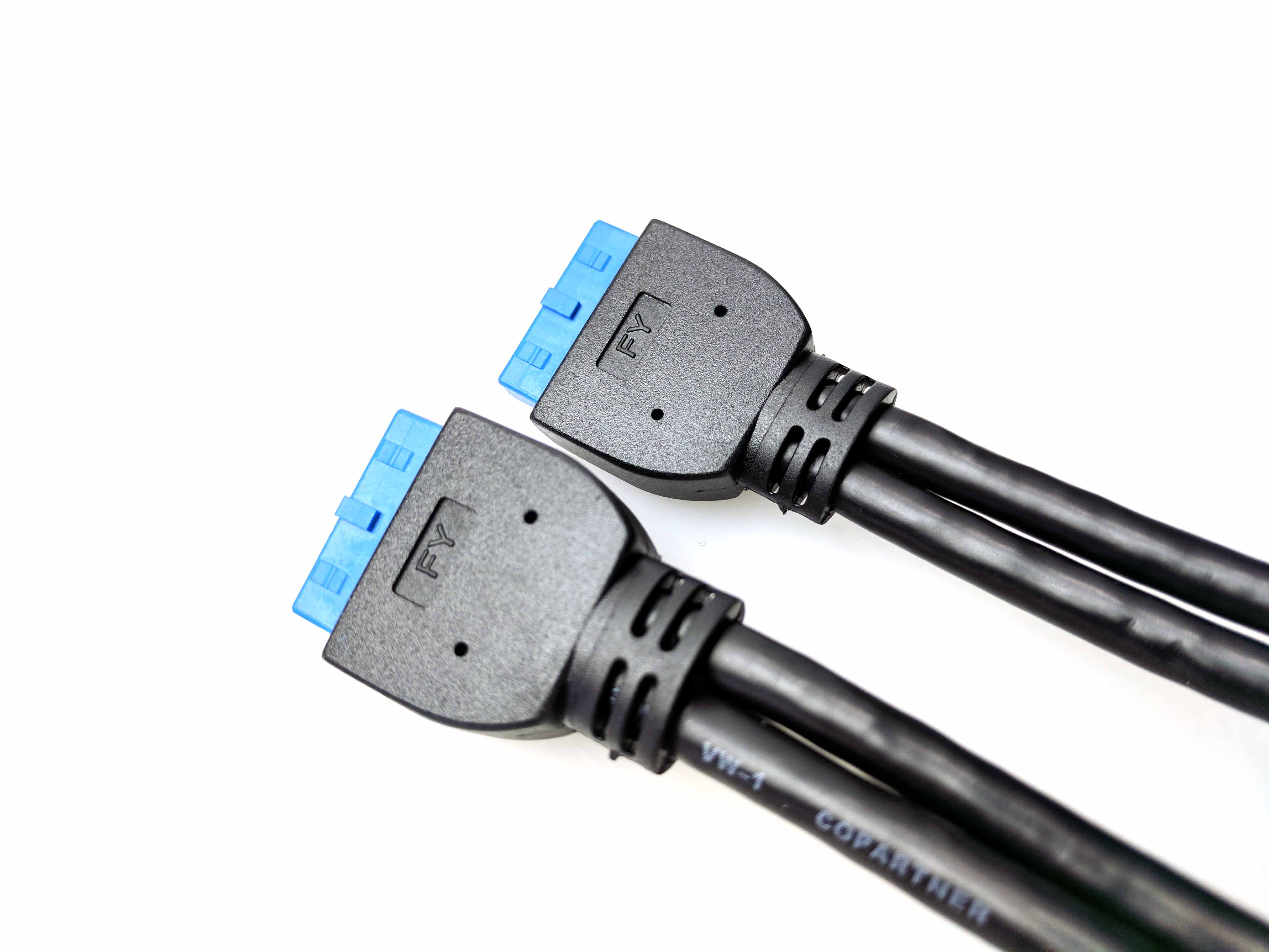
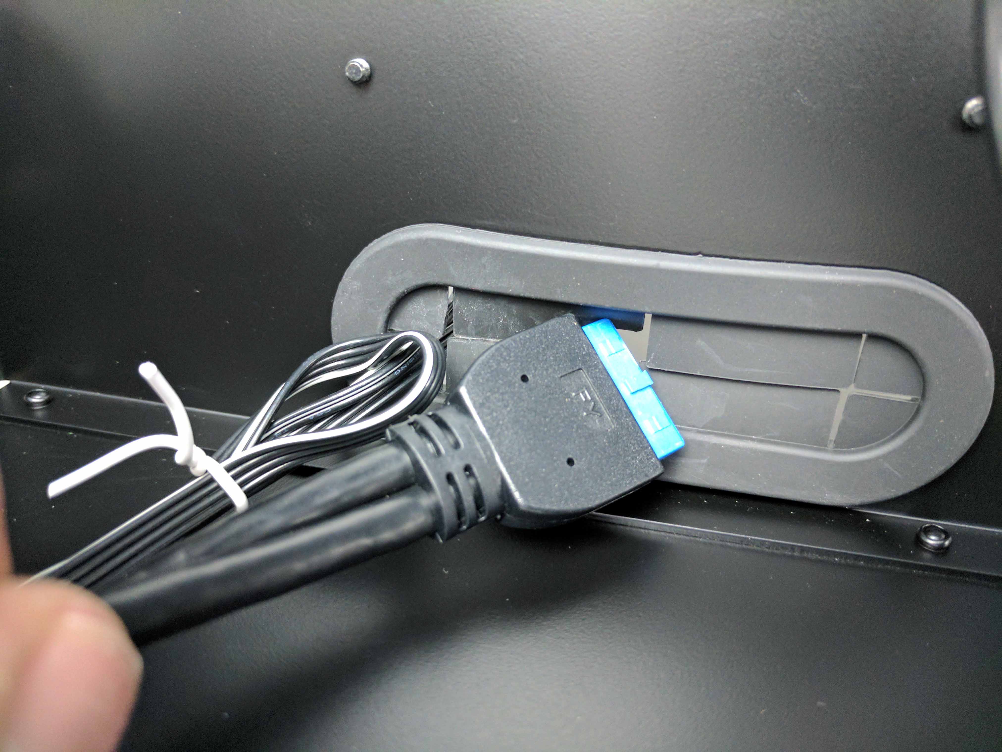
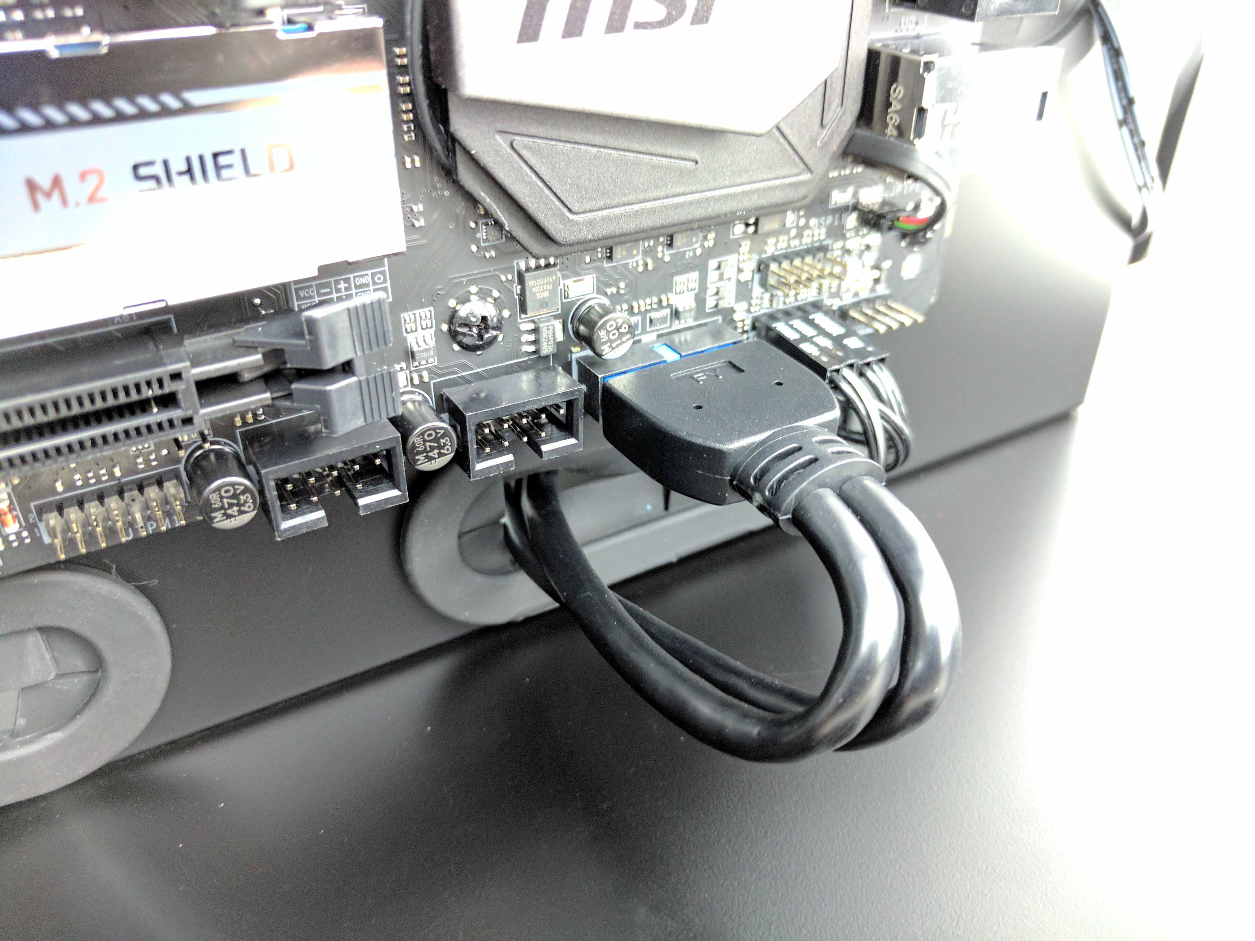
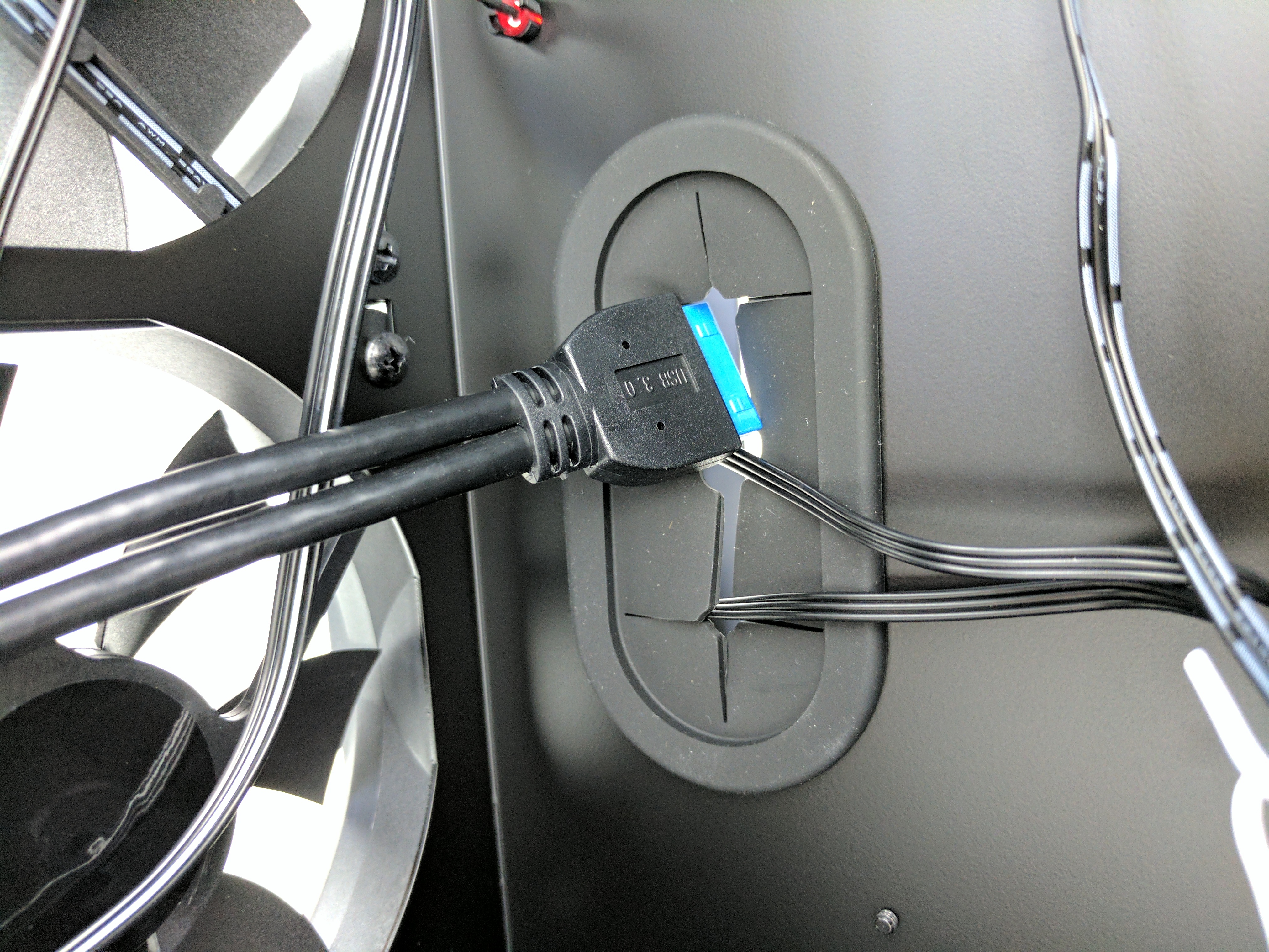
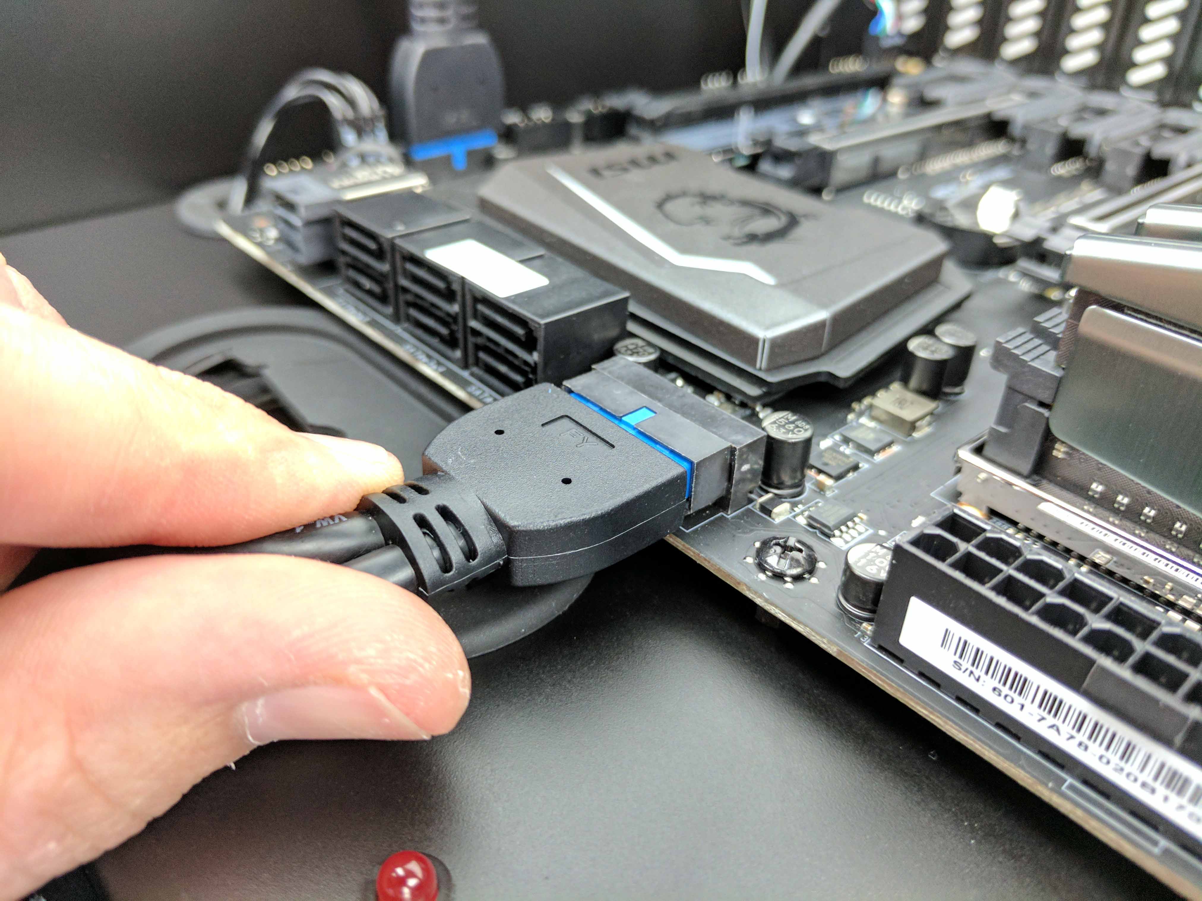
Feed the other USB 3.0 cable through the lower vertical hole in the case (directly below the SATA ports on the motherboard). Connect it to the USB 3.0 header (which is positioned sideways), and again, run the excess back into the drive chamber. Tie both USB 3.0 cables in with the front panel I/O wires using the existing tie wrap. Use a new white tie wrap to hold the two USB 3.0 cables together at the end of their natural loop in the chassis.
Get Tom's Hardware's best news and in-depth reviews, straight to your inbox.
Cooling
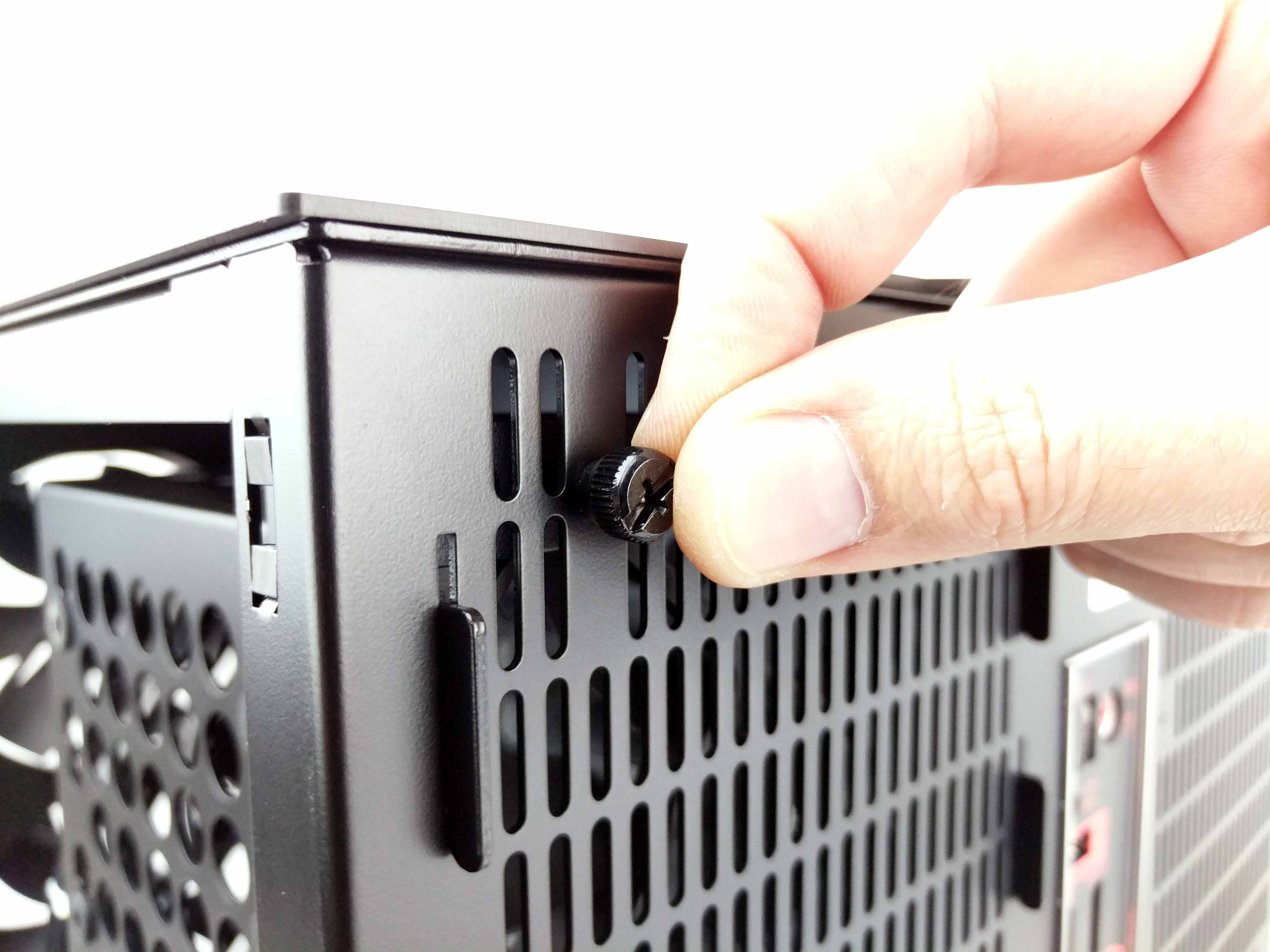
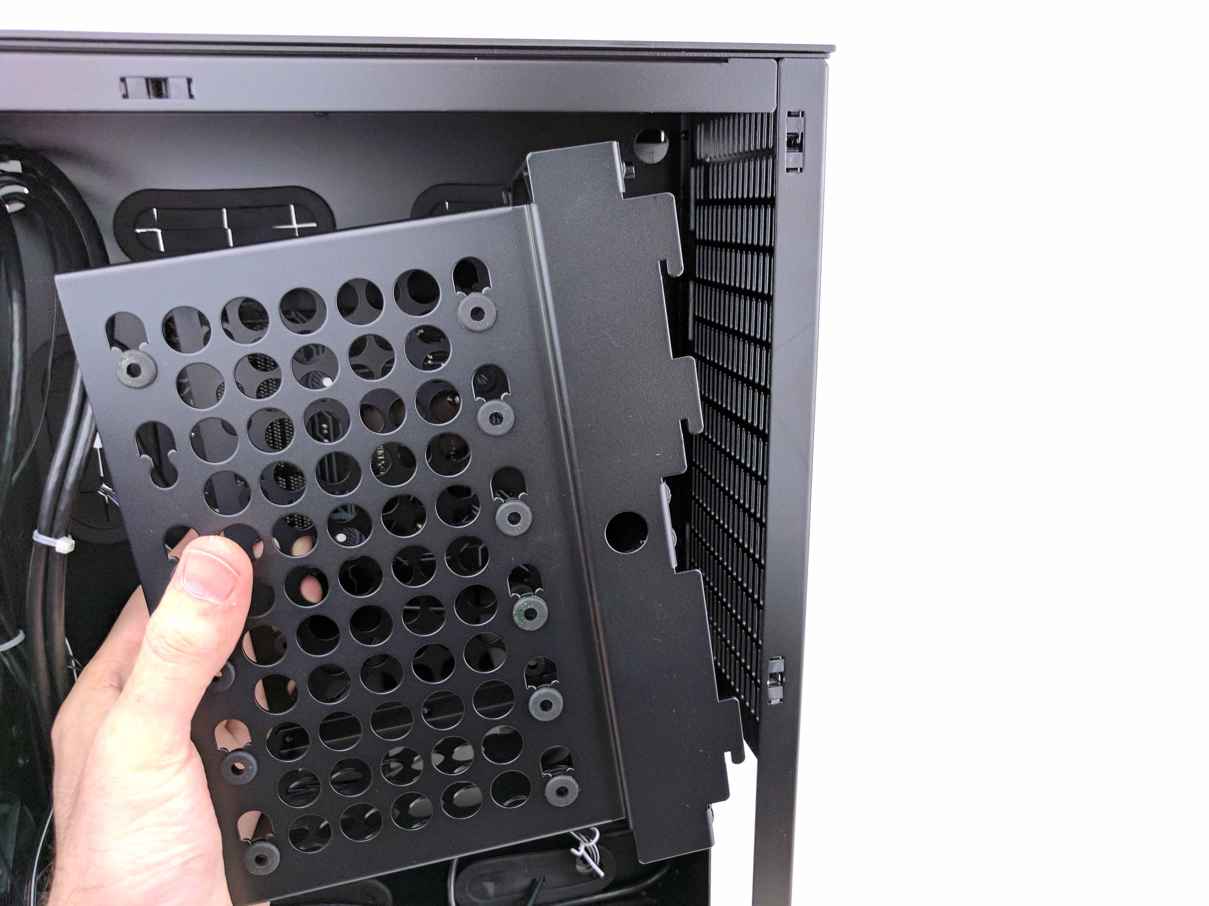
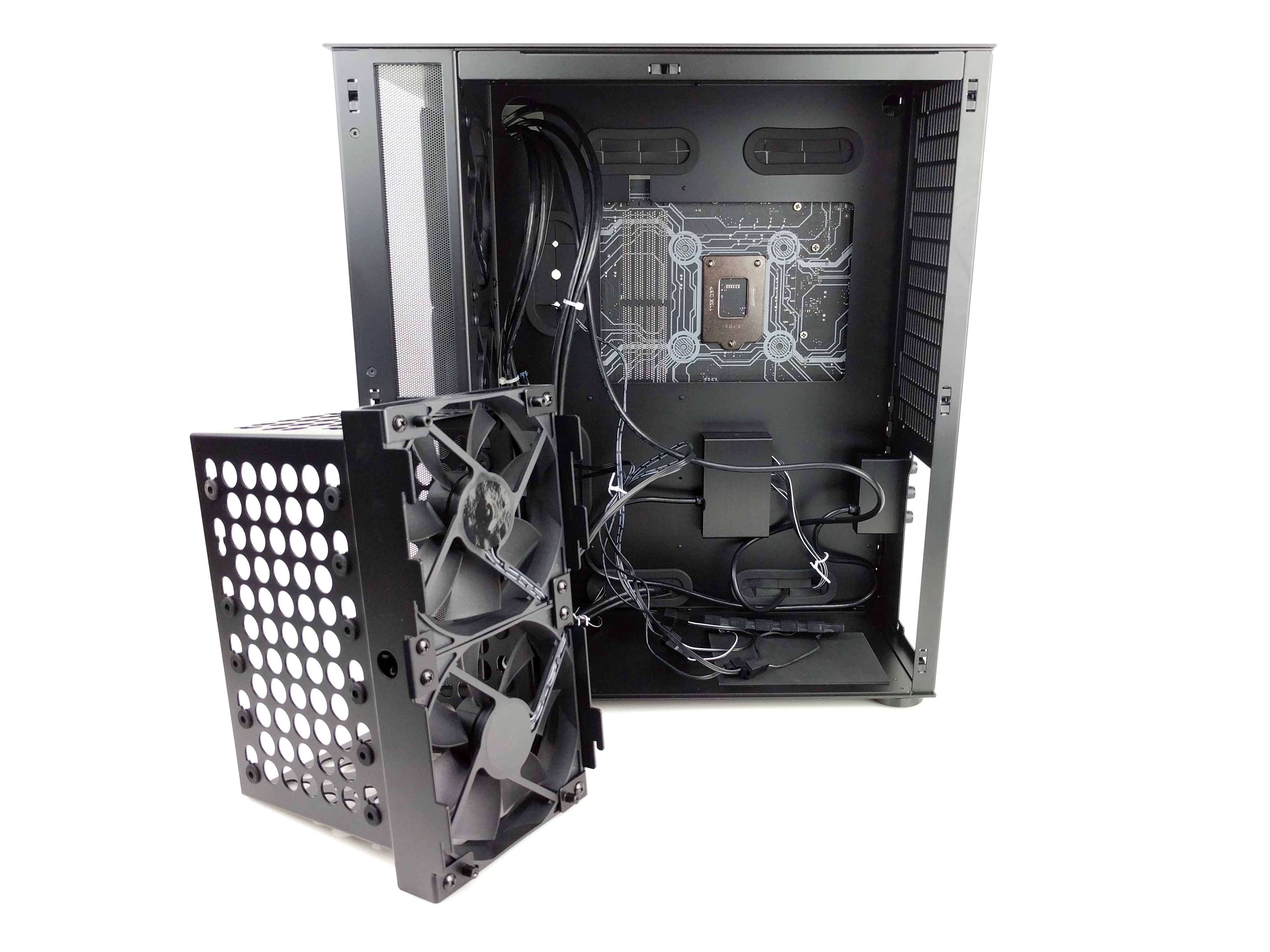
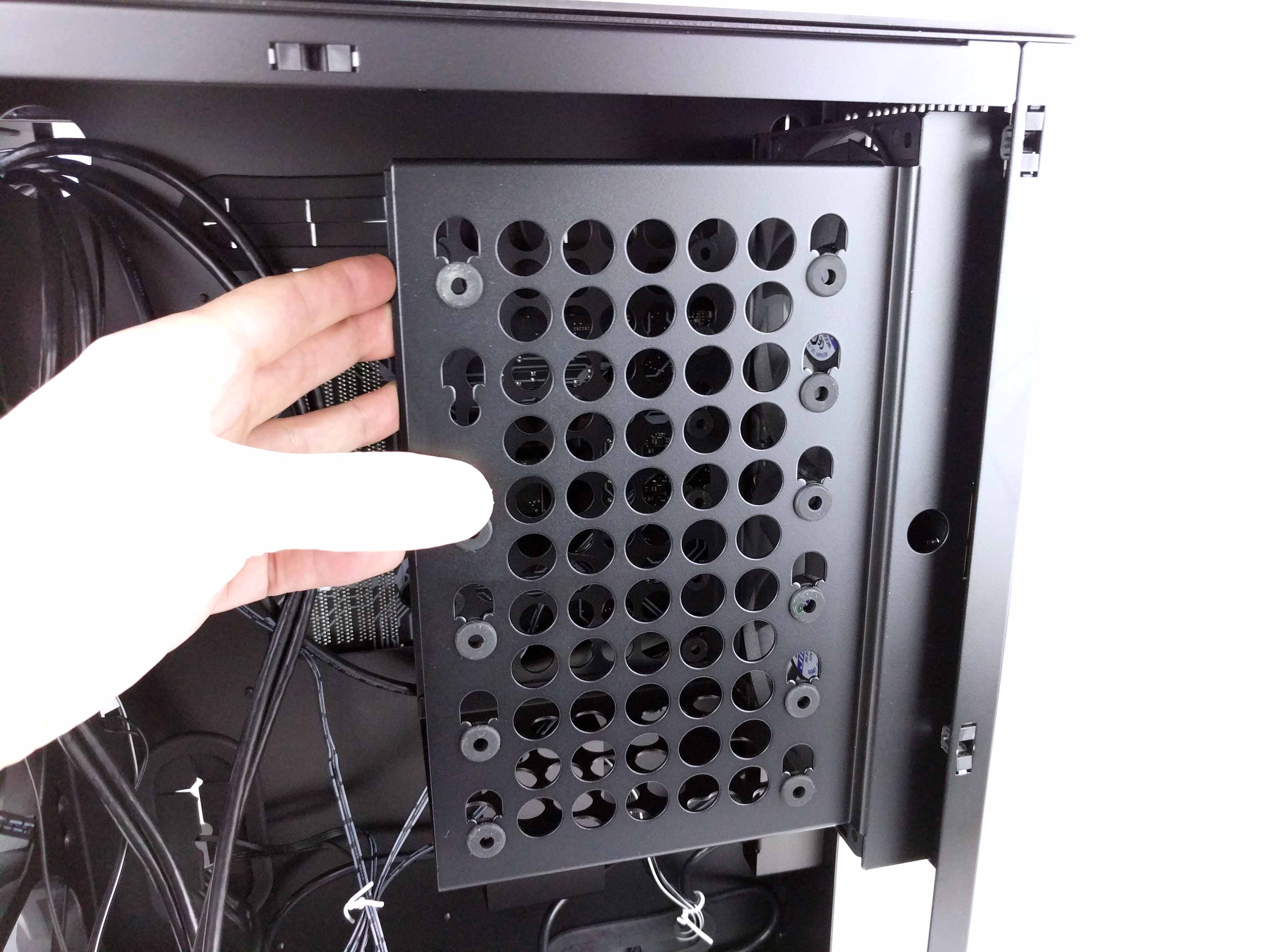
To properly install the CPU cooler, we have to first remove the drive cage in the PSU chamber of the chassis. Start by unscrewing the four thumb screws on the back of the case (below the motherboard’s rear I/O panel). Once they are removed, lift the drive bay up and away from the case. The bay will have to remain close by, because the fans attached to it are already tied in with the rest (see last picture in the album below).
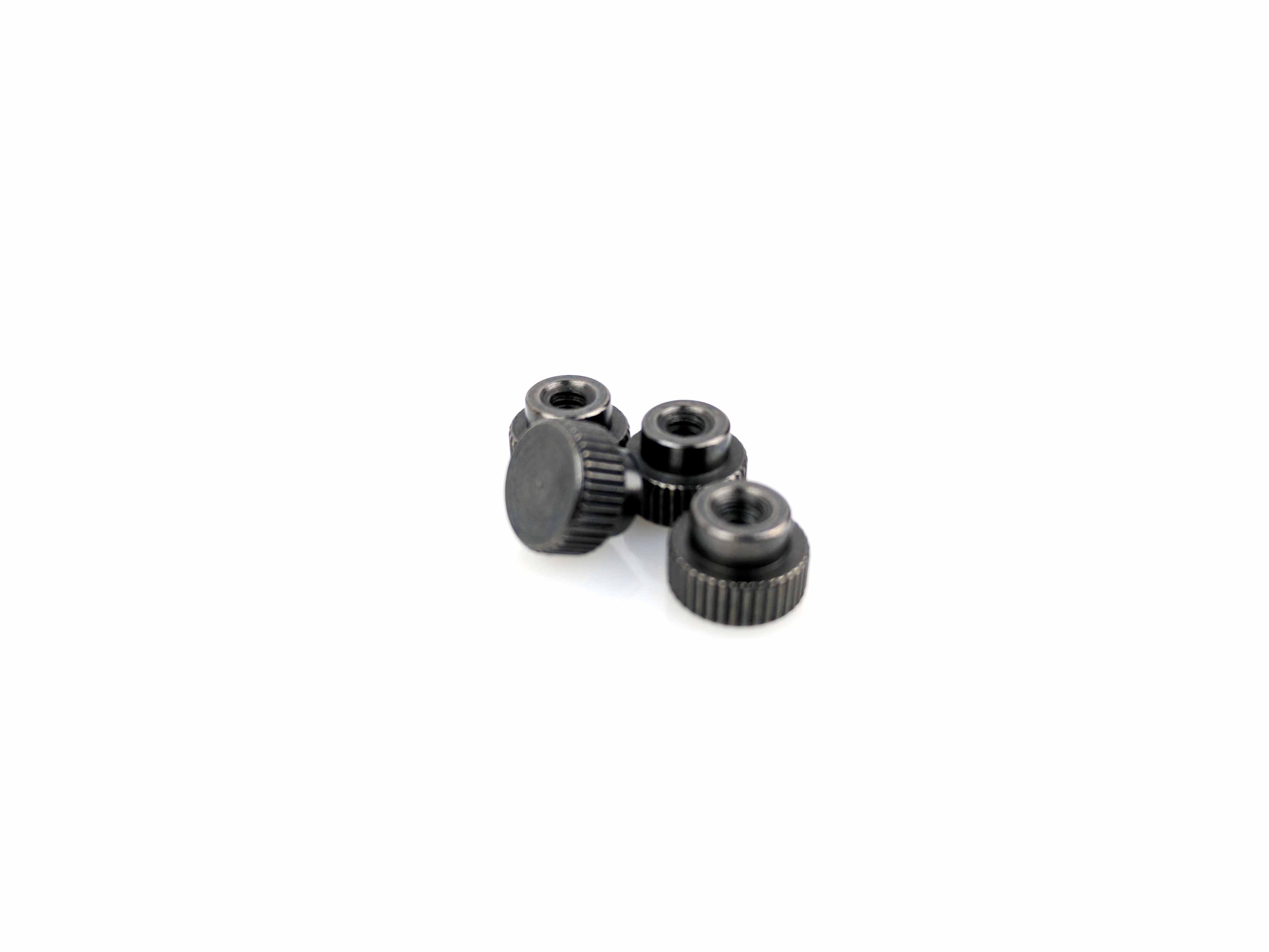
Remove the Cryorig H5 Universal CPU cooler from its box, along with the backplate, female-to-male thumbscrews, the support bars for Intel motherboards, the foam square, and the thumbscrew caps. Peel the sticker off of the foam square and attach the foam square to the center square of the backplate (post side).
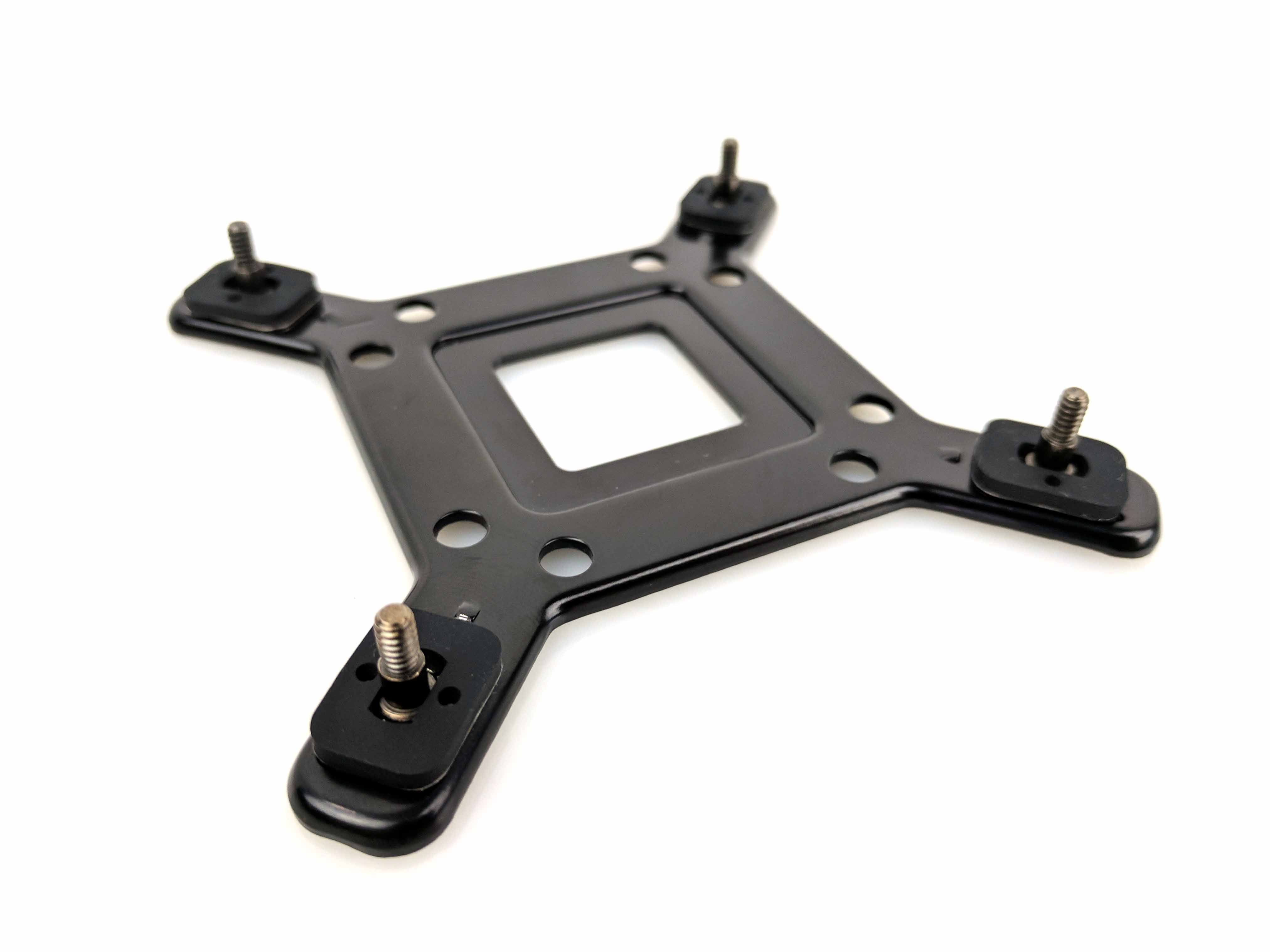
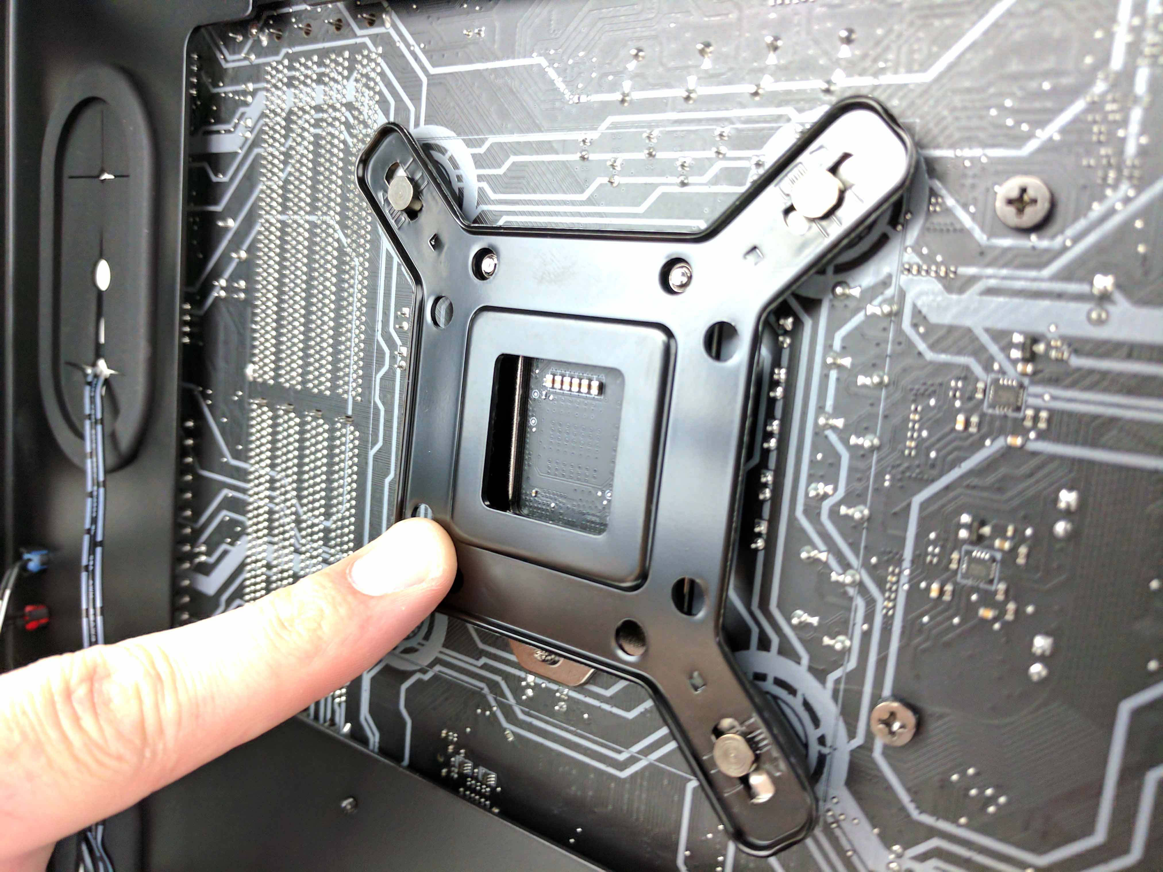
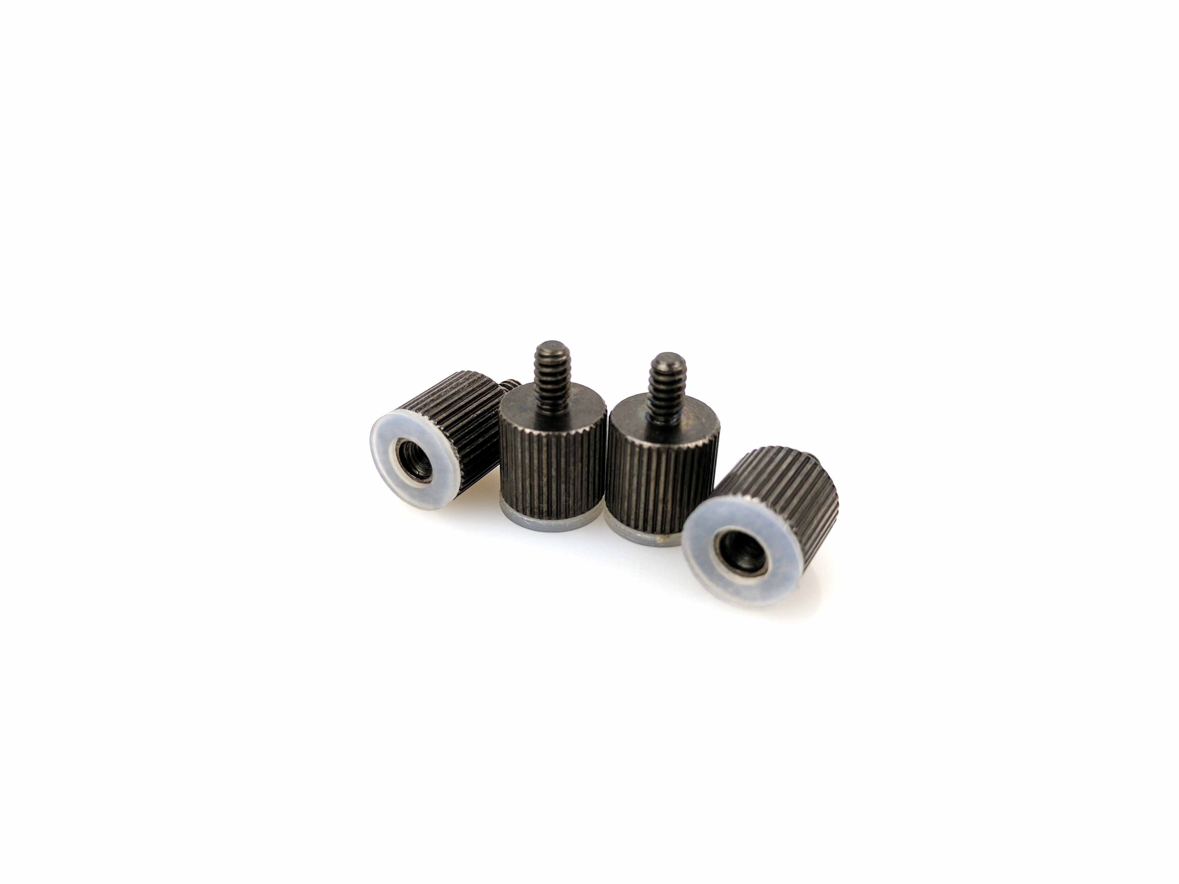
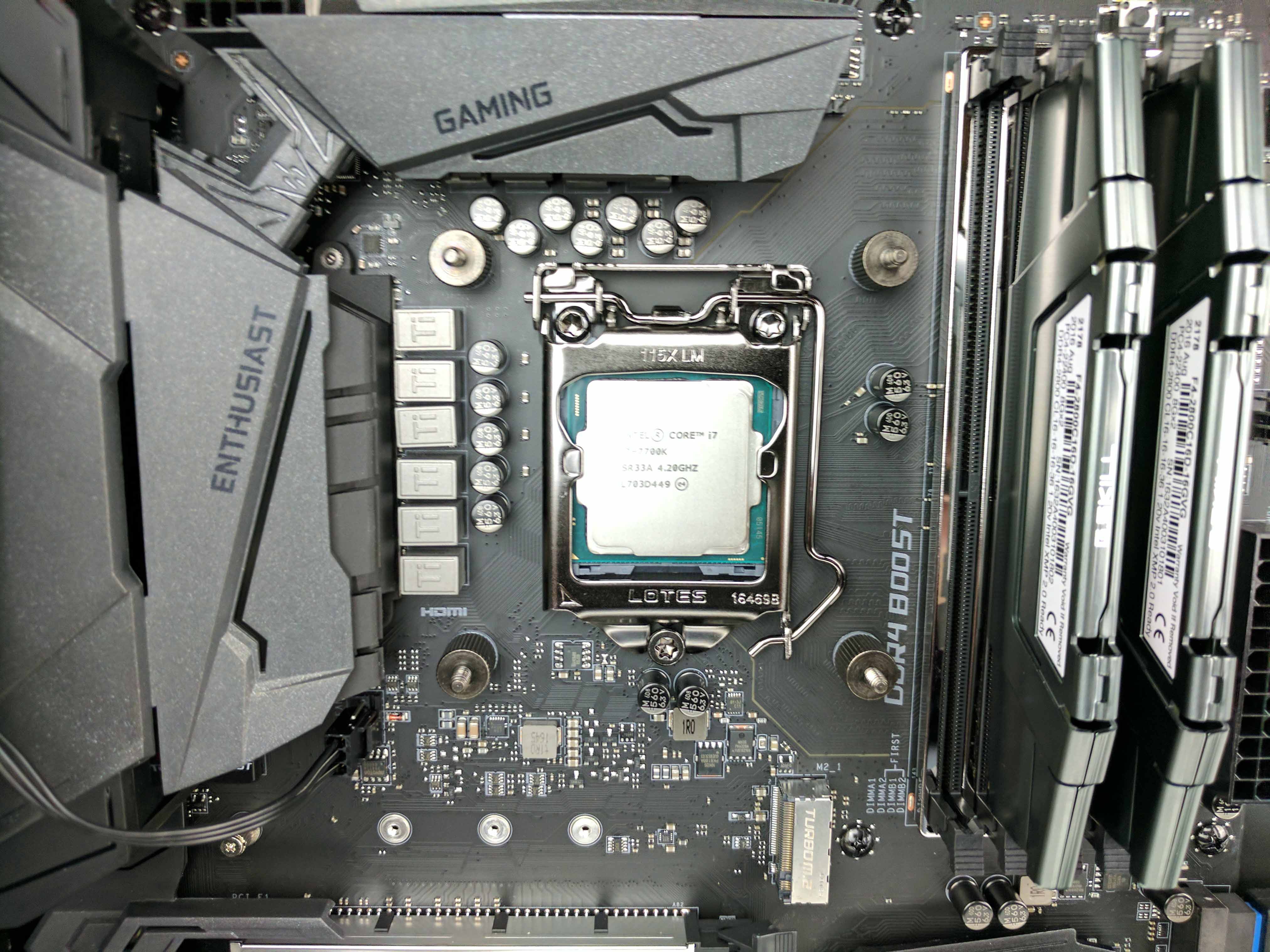
Set each of the four posts in the backplate to the B position and line it up with the holes near the CPU on the backside of the motherboard (see the 2nd picture above). Hold it in place with one hand as you go to the other side (main chamber) and thread the four female-to-male thumbscrews to the posts in the backplate. At this point, replace the drive cage to its original position by sliding it into the guides and refastening the thumbscrews.
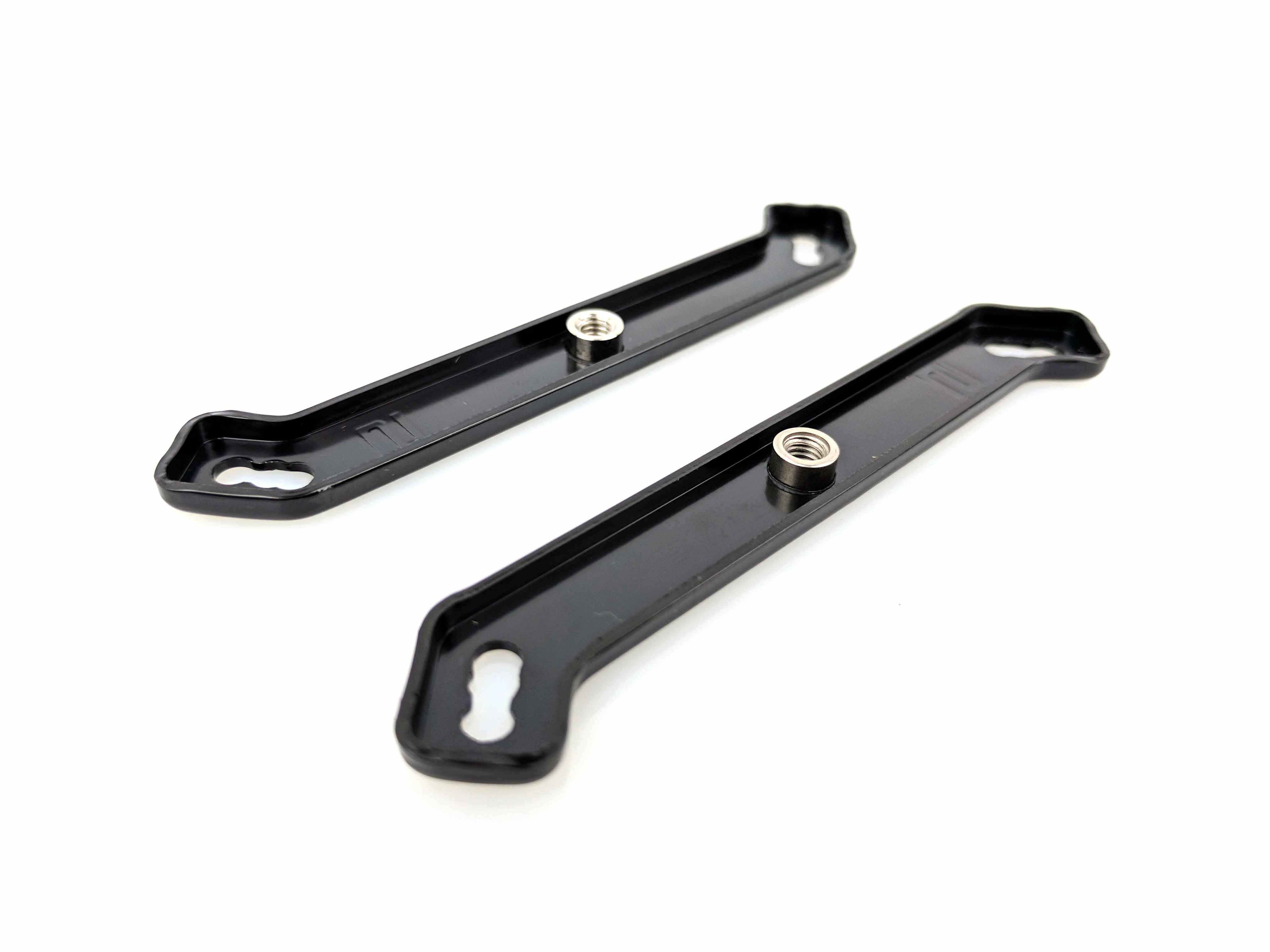
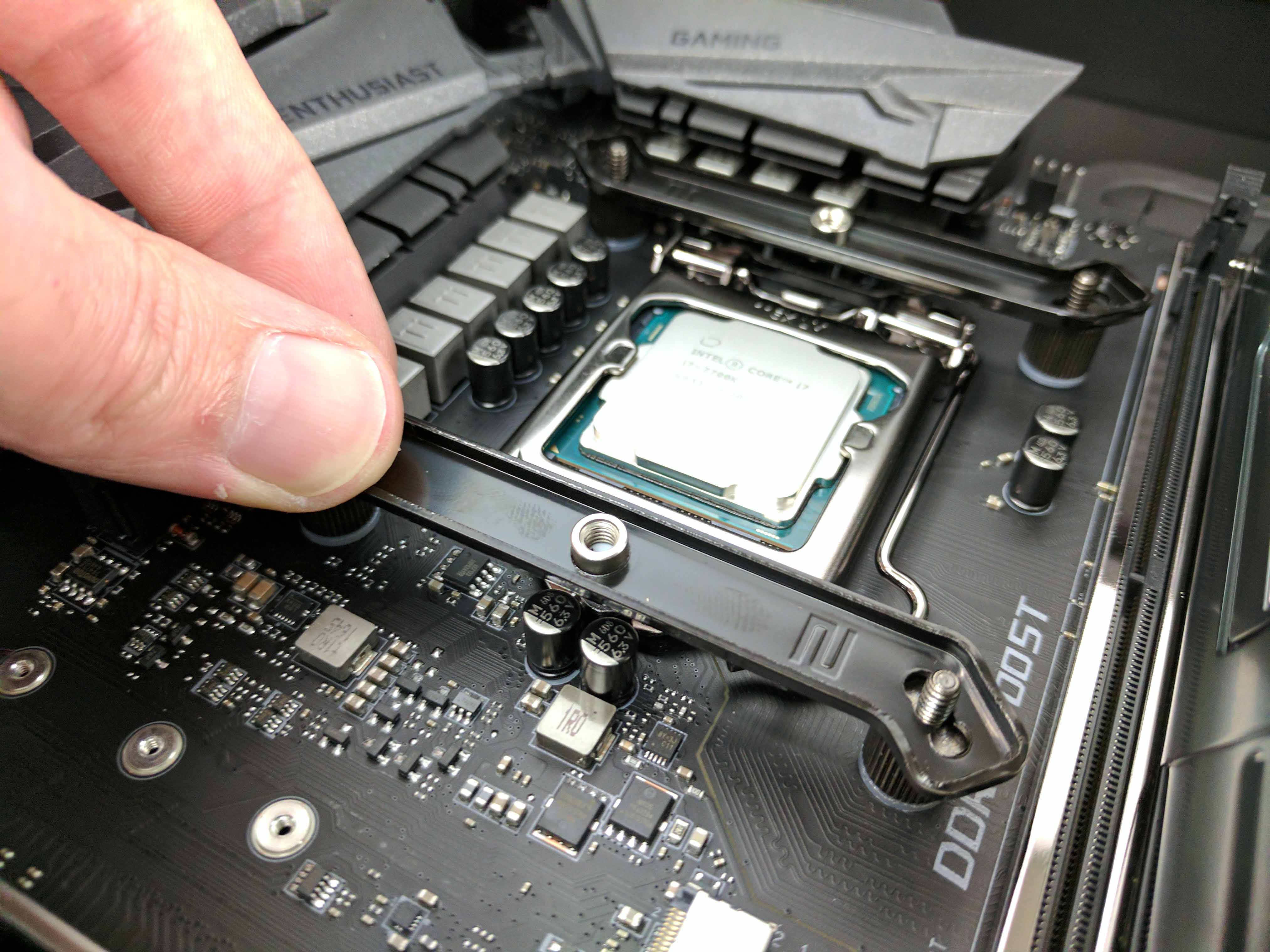
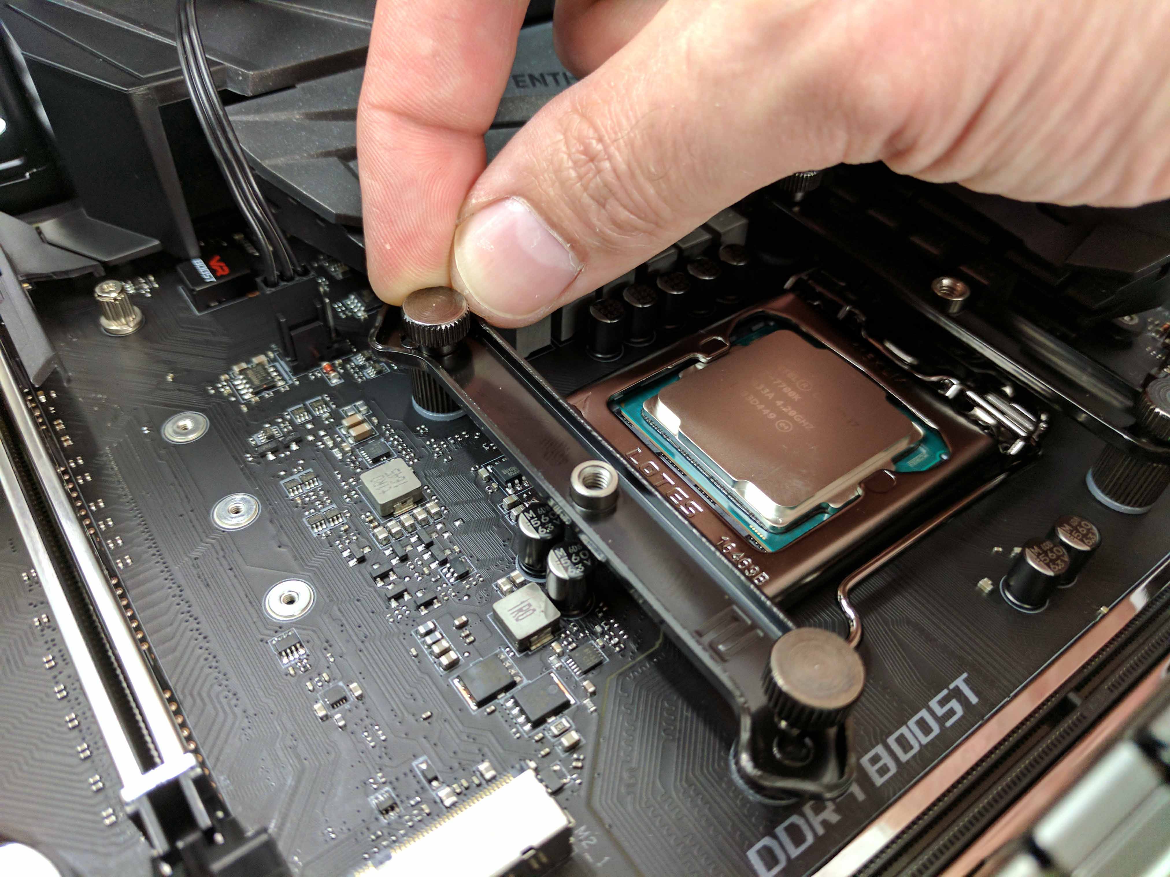
Set the PC on its right side again. Place the mounting bars (labeled “2”) horizontally across the top and bottom thumb screw posts with the numbered metal facing up and the curvature of the bars pointed outward (see slides 1 the album below). Secure them to the female-to-male posts using the thumbscrew caps (slide 3 and 4, below). Make sure the entire assembly is tight.
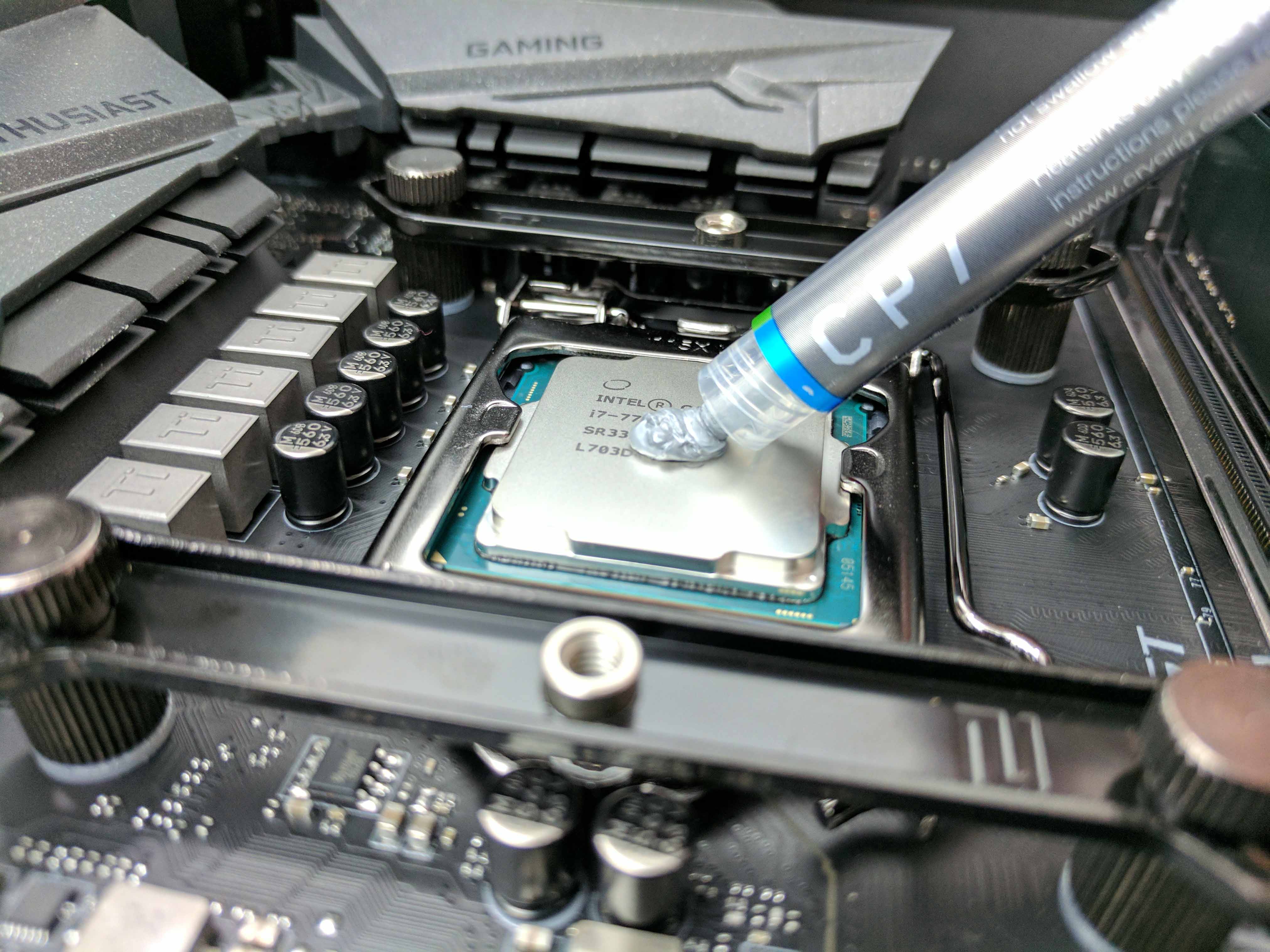
Grab the provided tube of thermal paste and apply it to the center of the CPU (see slide 1 below). Peel the protective sticker off the contact point of the heatsink and unwrap the fan cable. Lower the large cooler onto the processor (mind the CPU fan cable) and position the spring screws of the heatsink over the center holes in the mounting bars (see slide 6 below).
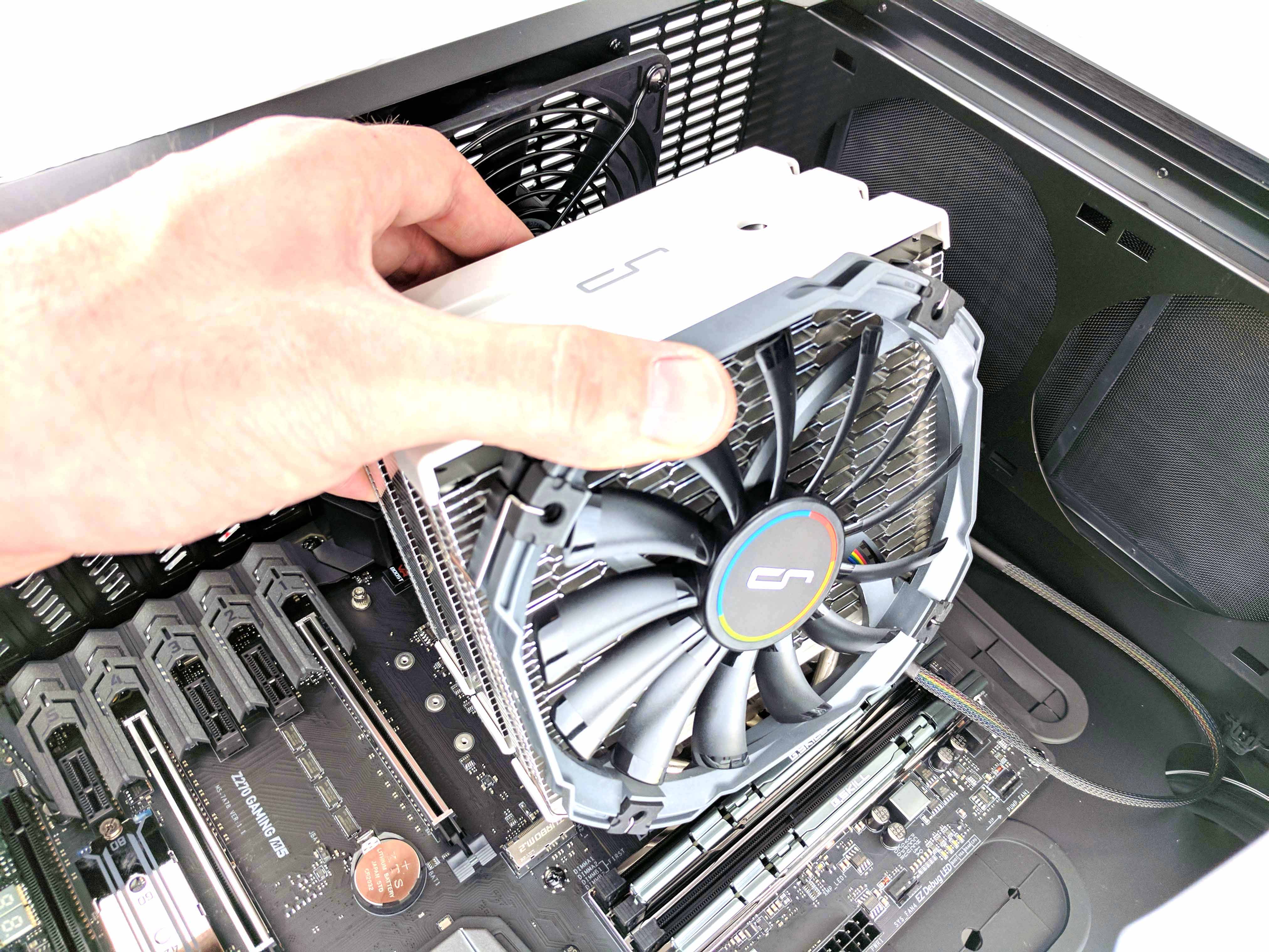
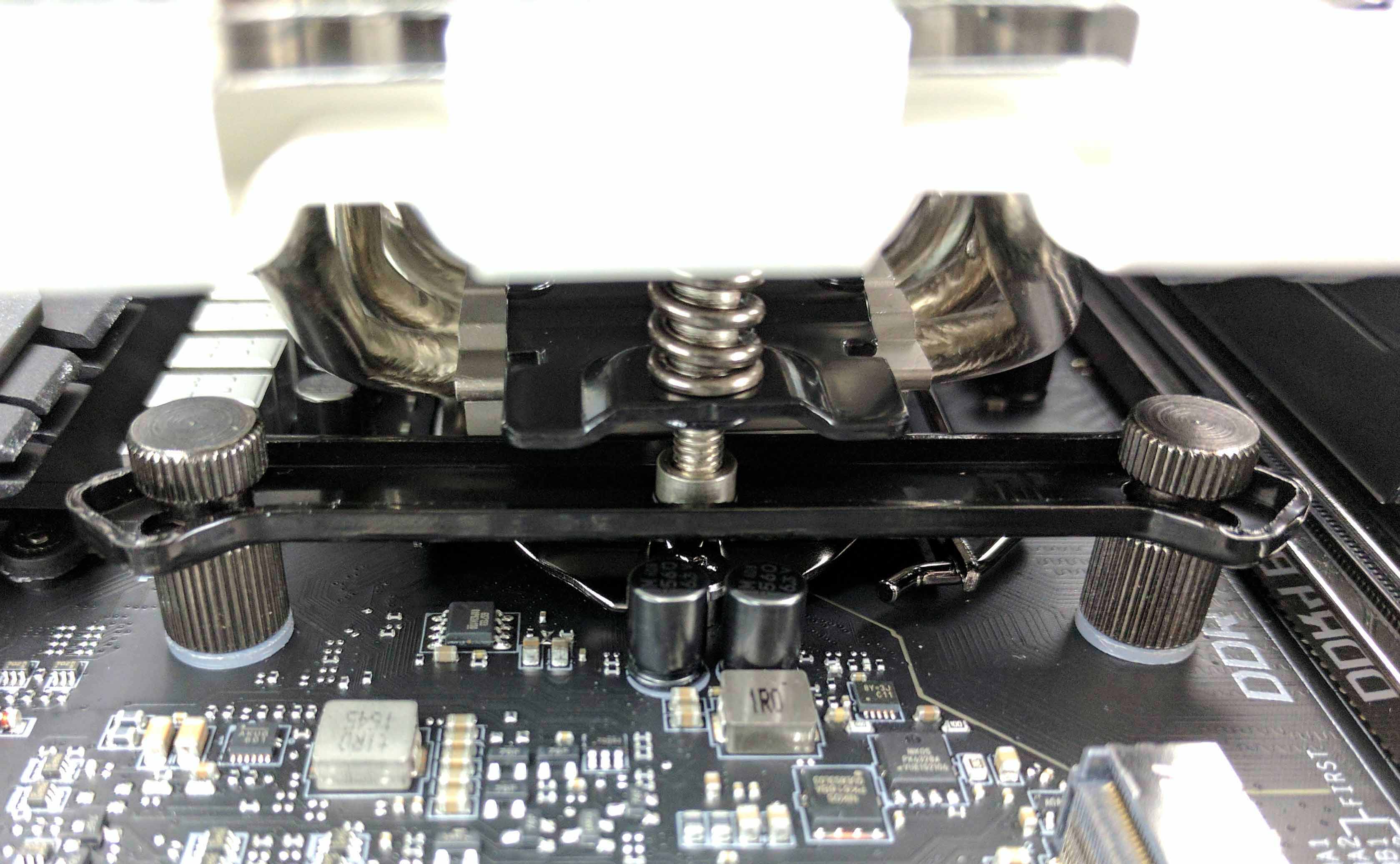
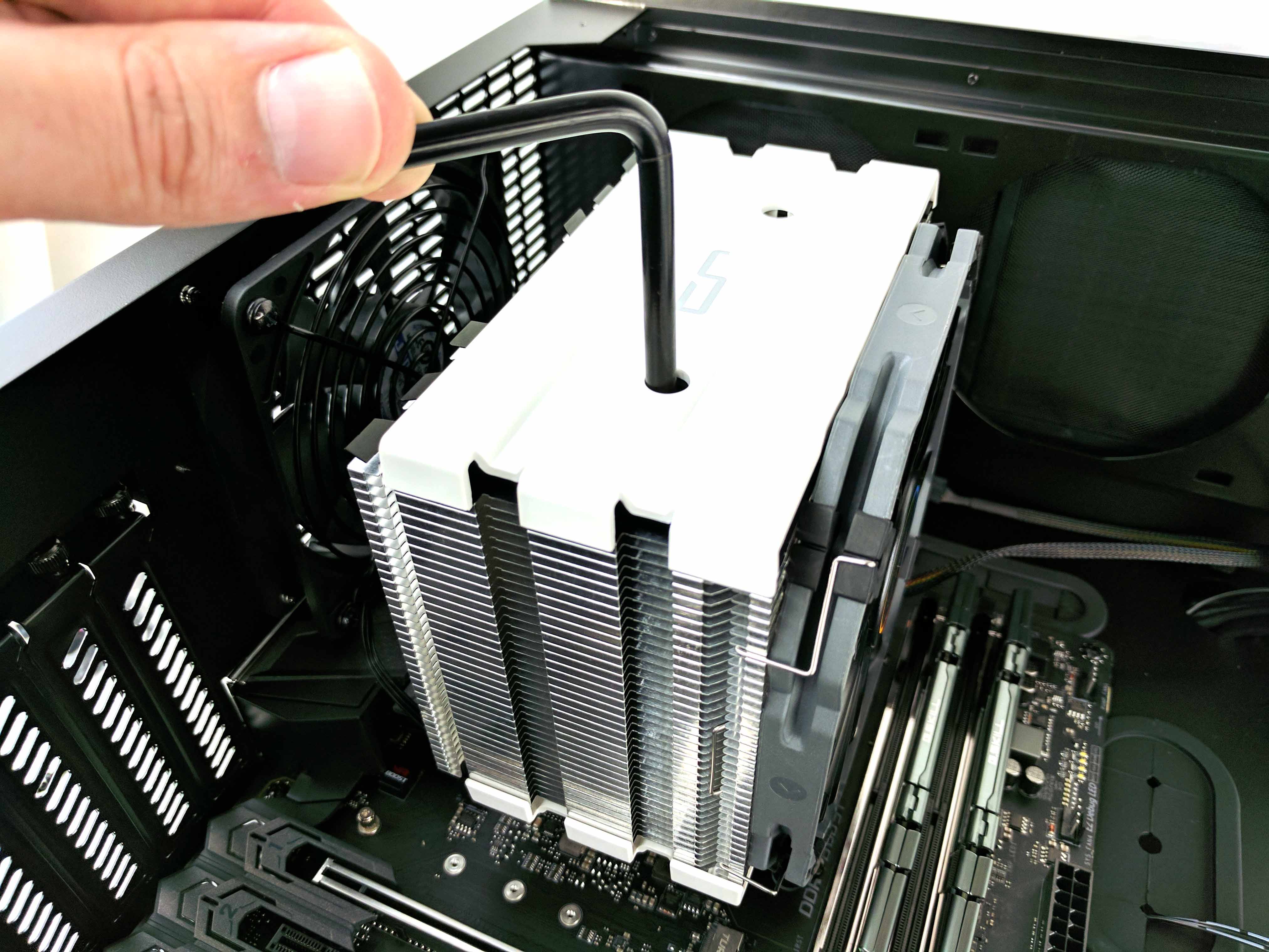
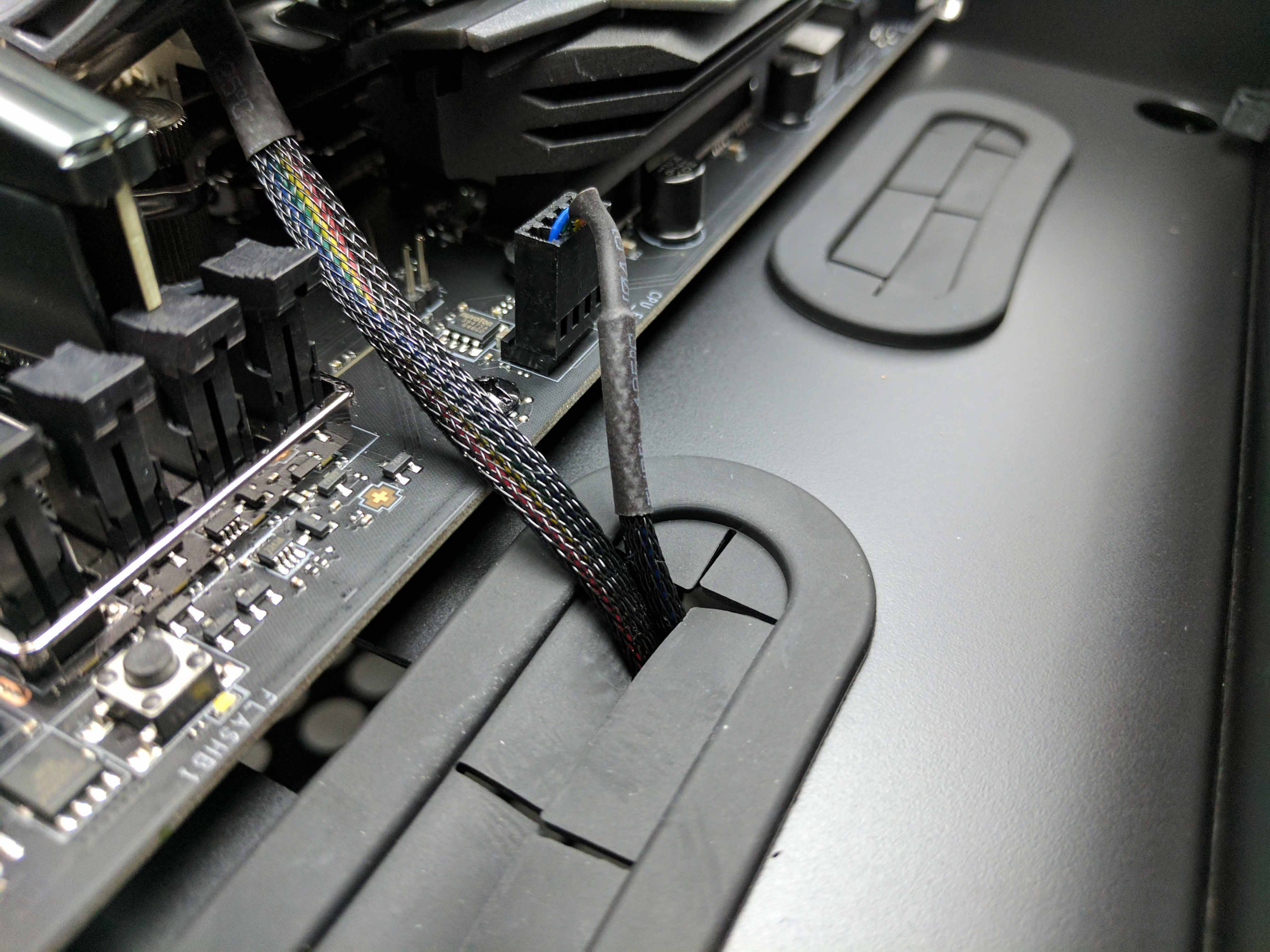
Slide the included tool (a long Phillips-head screwdriver) down one of the shafts in the center of the heatsink (see slide 4 in the album above) and tighten the screw just enough to thread the mounting bar. Then switch shafts and get the other to thread. Tighten both screws all the way, making sure to alternate shafts after every few turns of the screwdriver until you cannot tighten it anymore. Connect the CPU fan’s cable to the CPU_FAN1 header and tuck the excess away (loop it and feed to the nearby hole in the case).
Power Supply
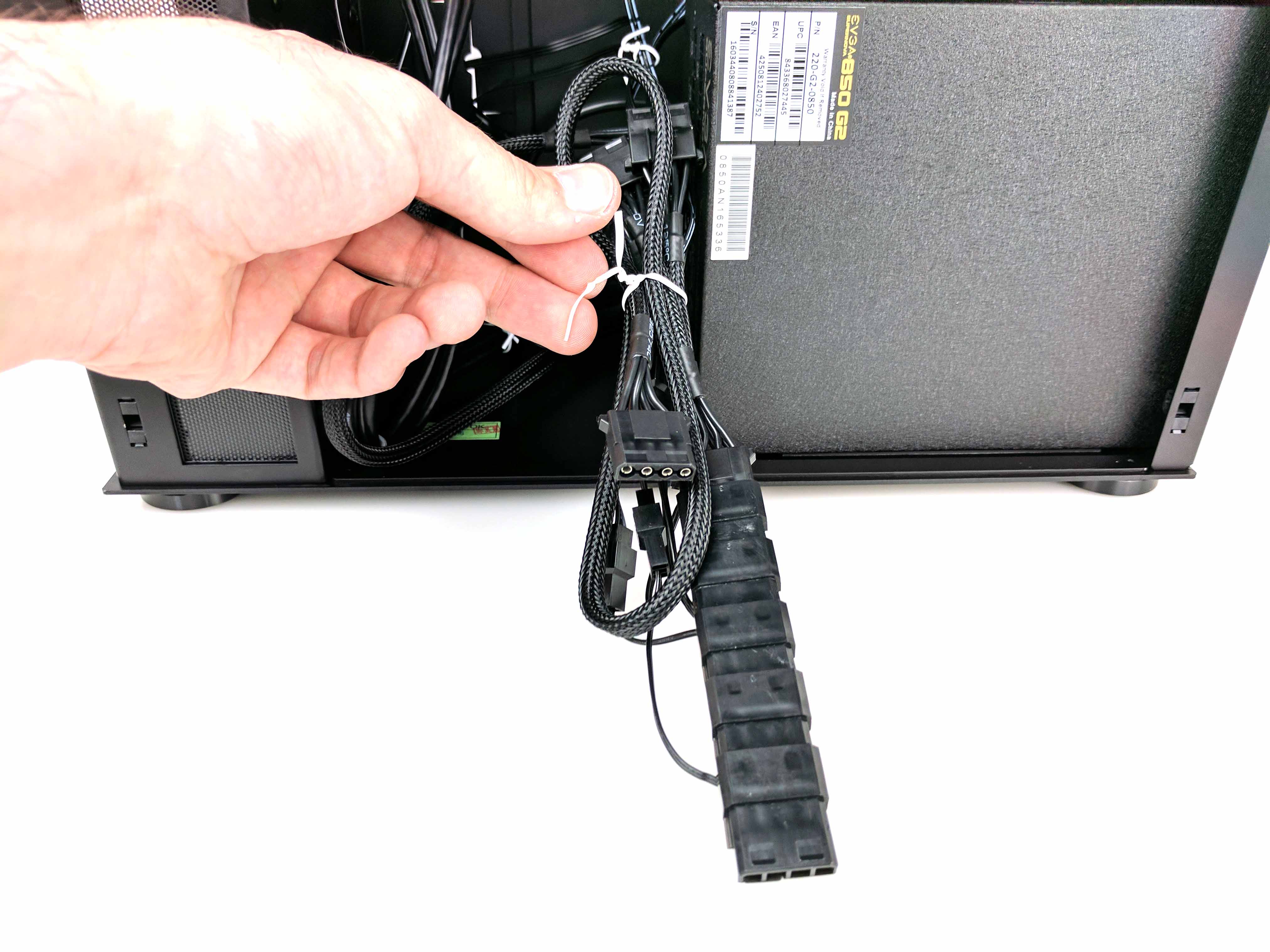
Set the case upright again (it should start to feel pretty heavy with the cooler attached). Remove the EVGA 850 G2 power supply from its box, along with one of the SATA power cables. Take the cable and attach it to the RGB LED controller using the first lead in the strand. Tie up the excess SATA plugs with the existing wiring (using the existing tie wrap).
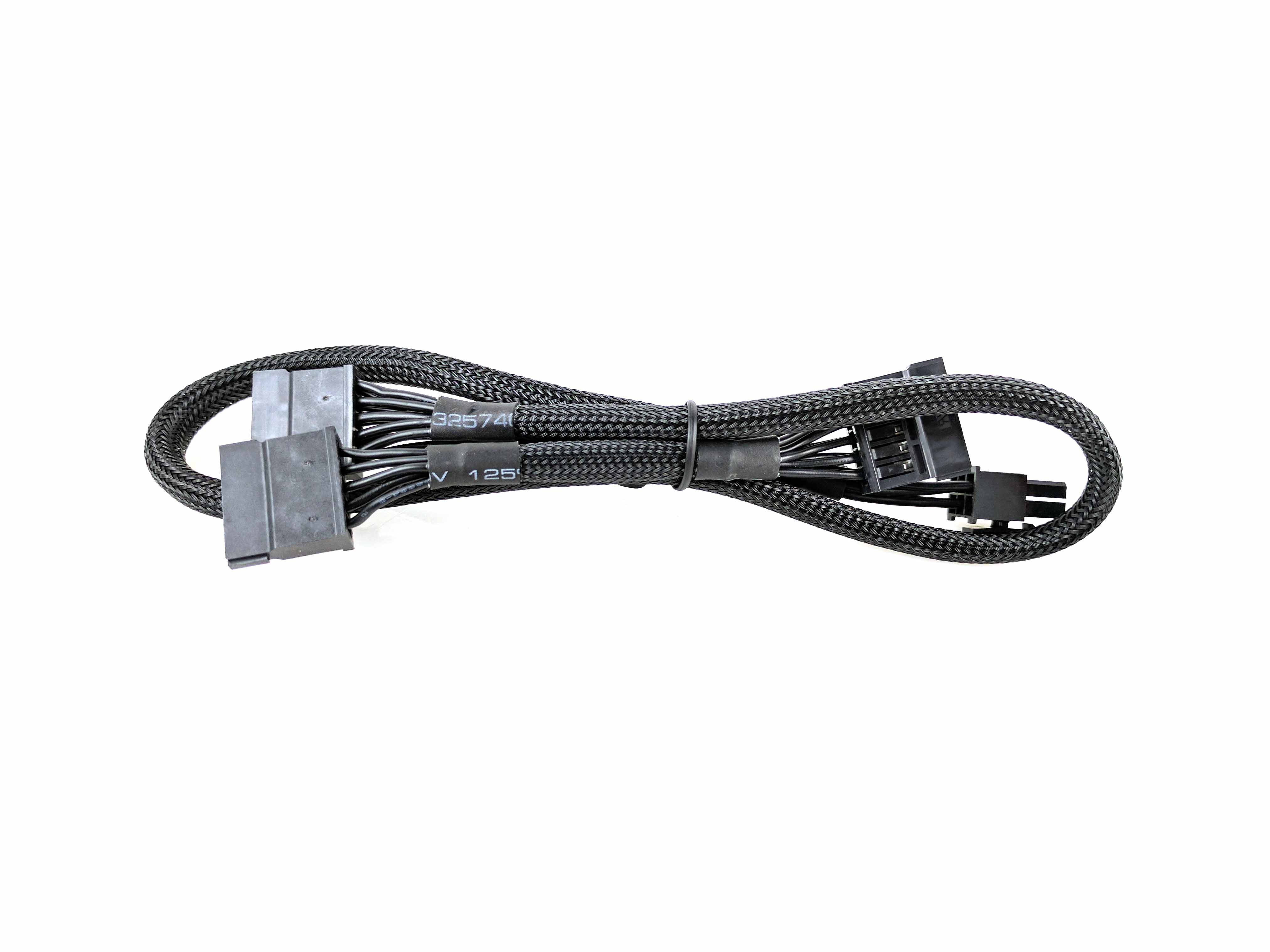
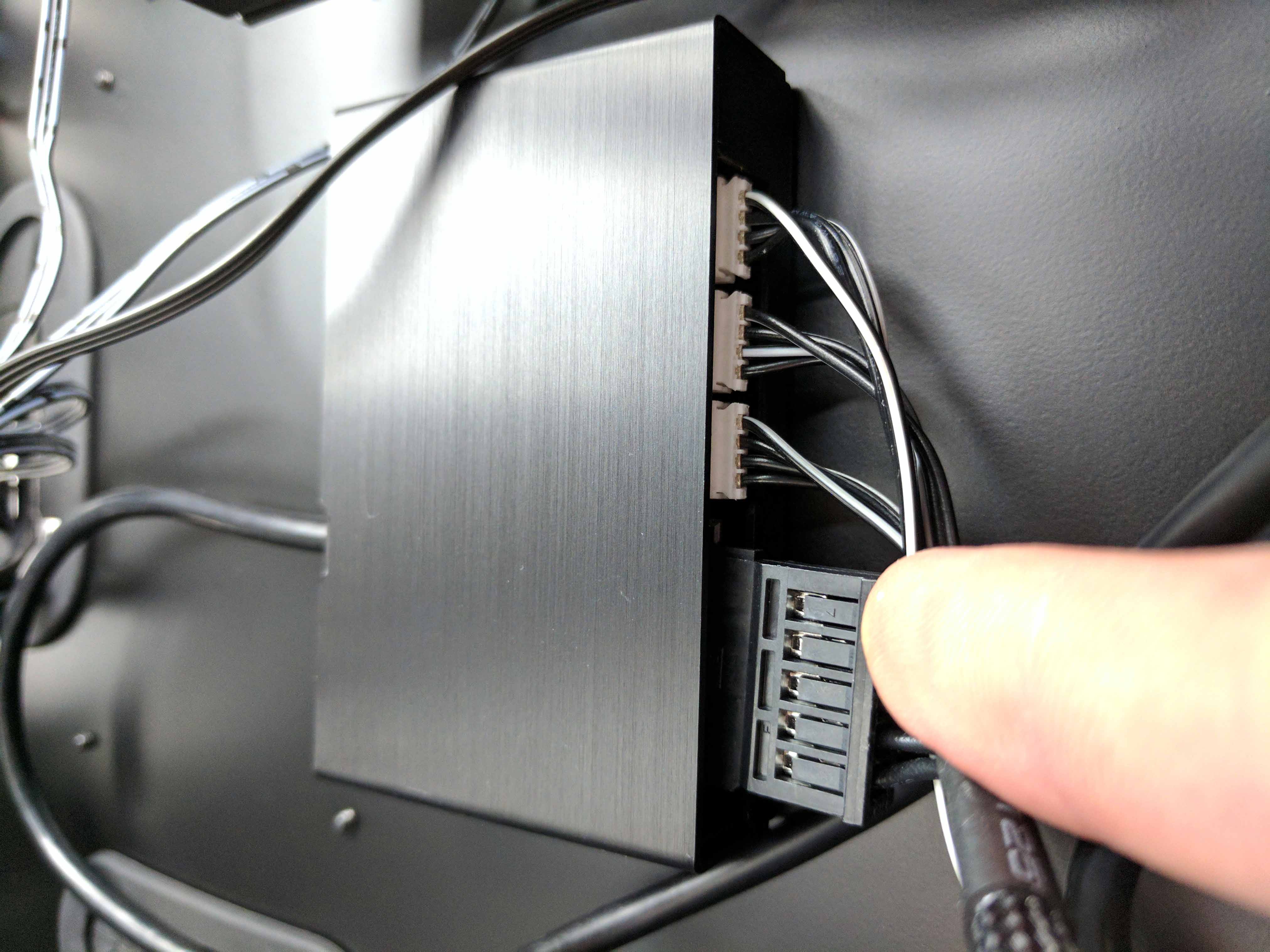
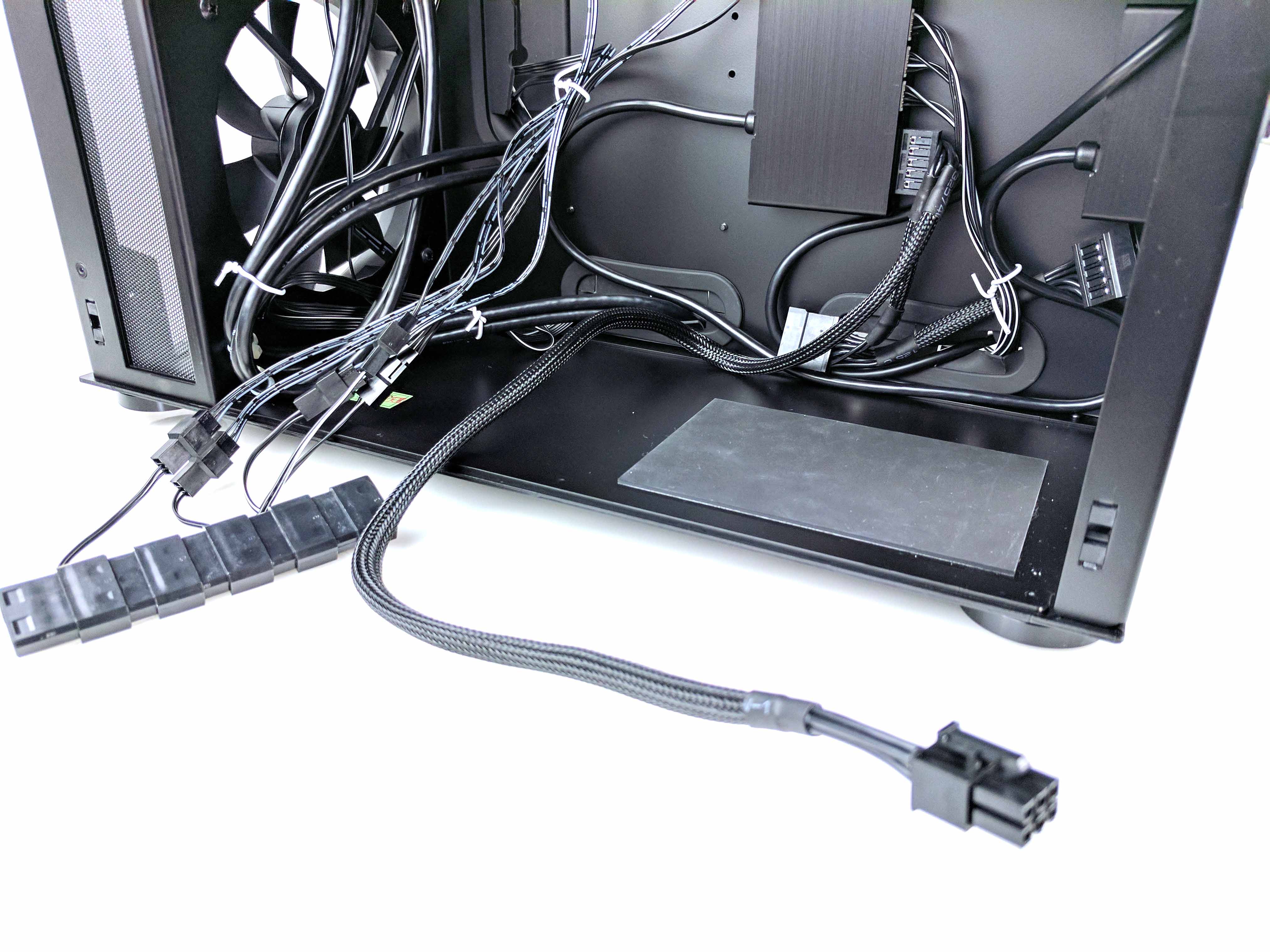
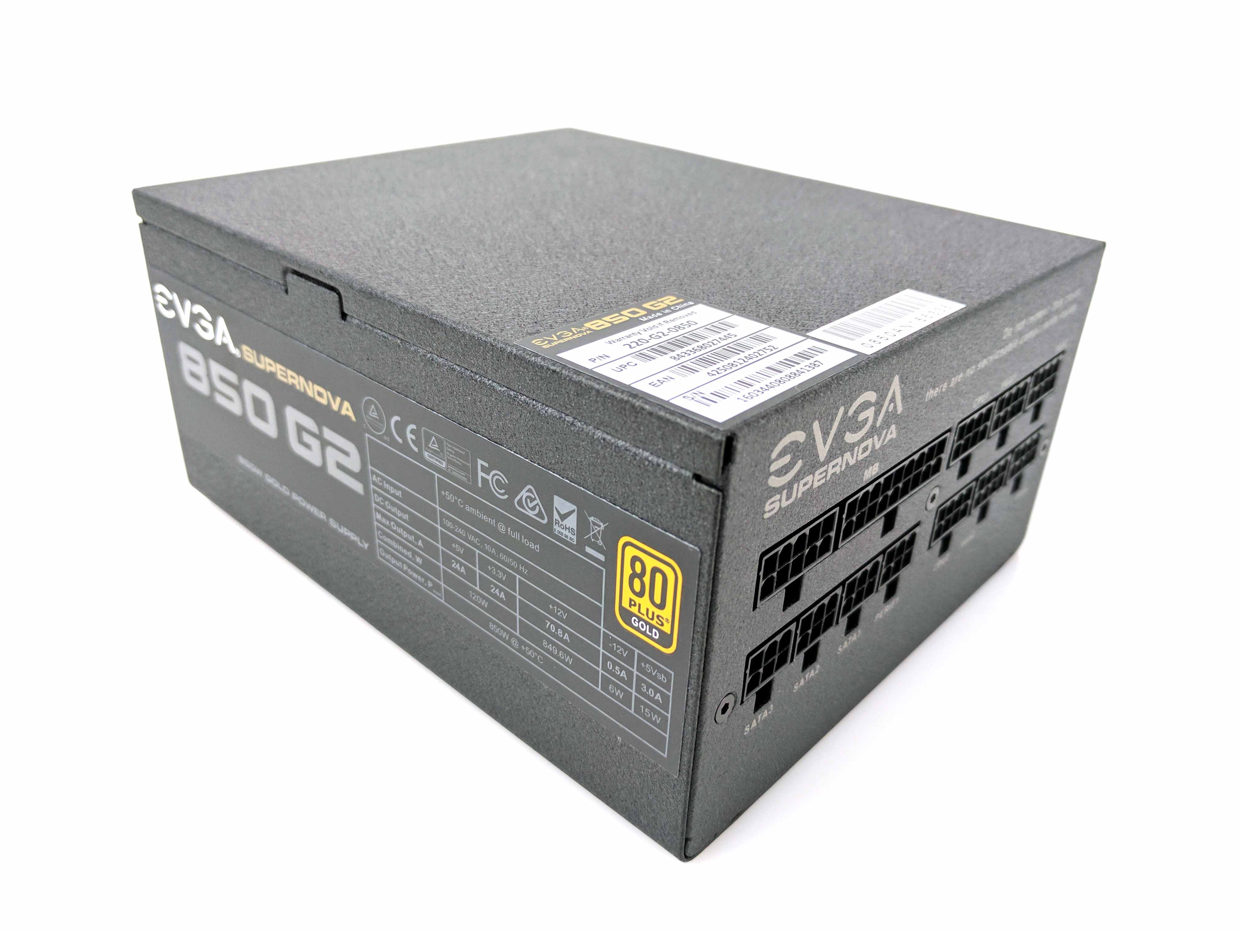
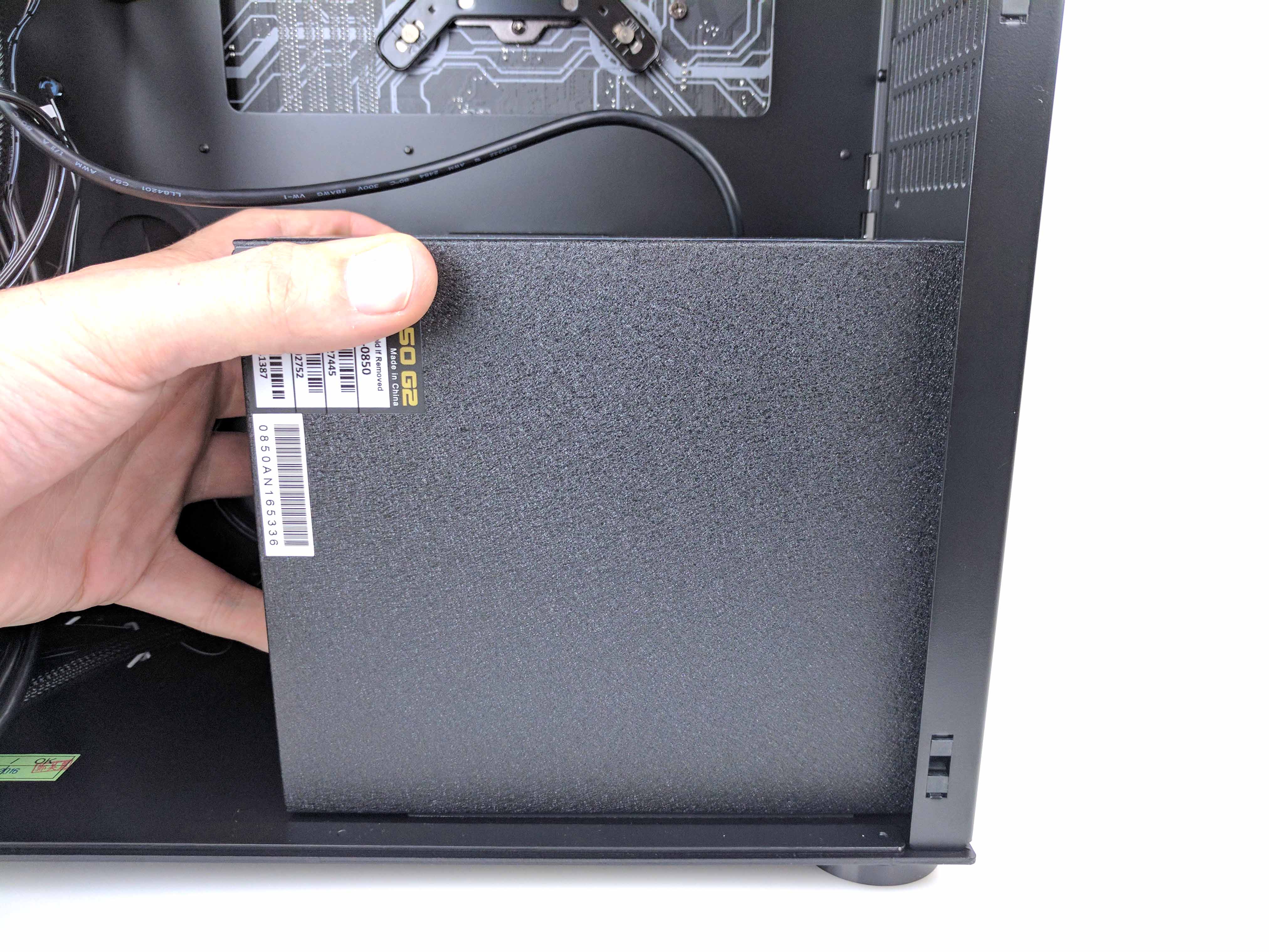
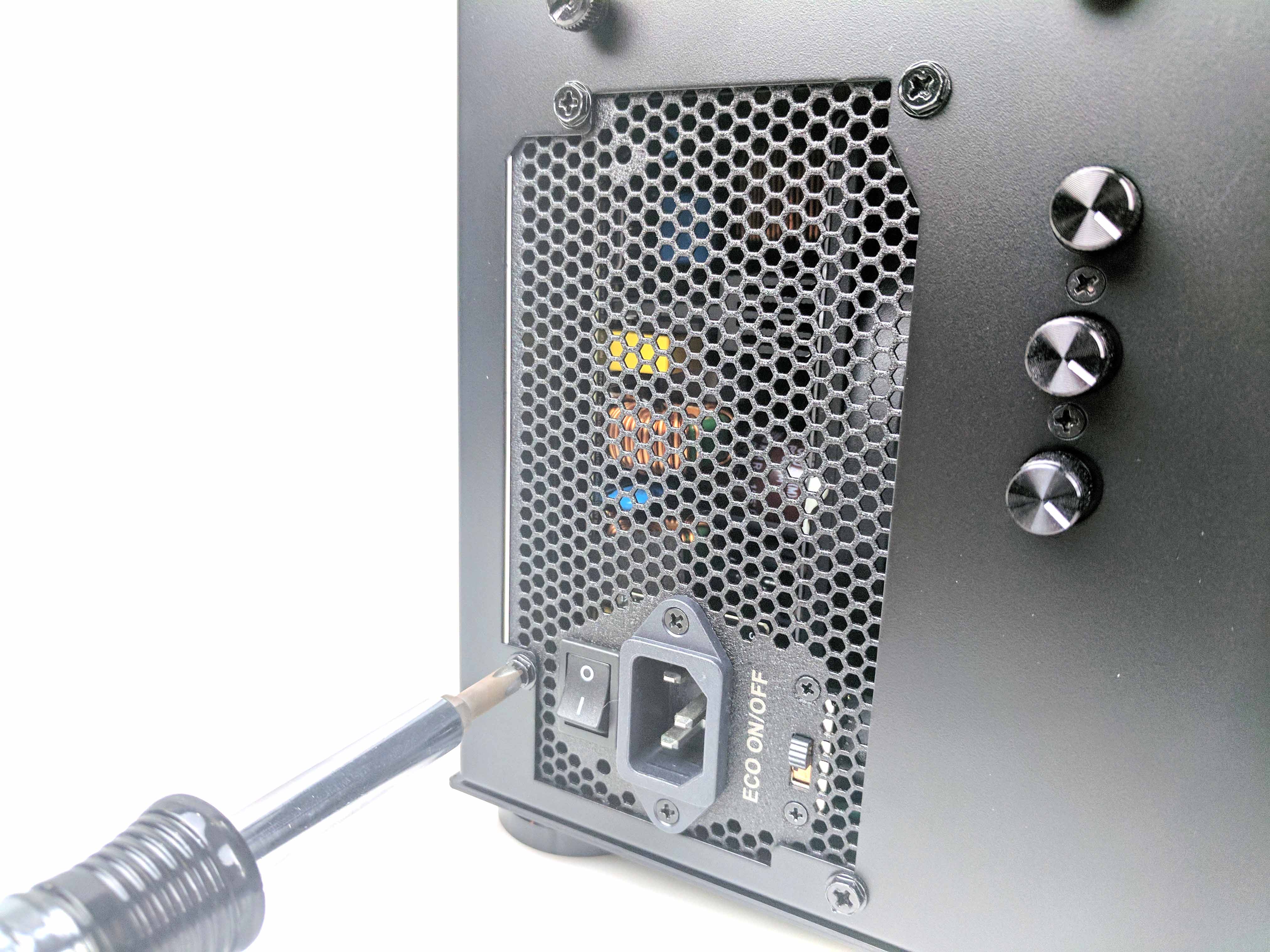
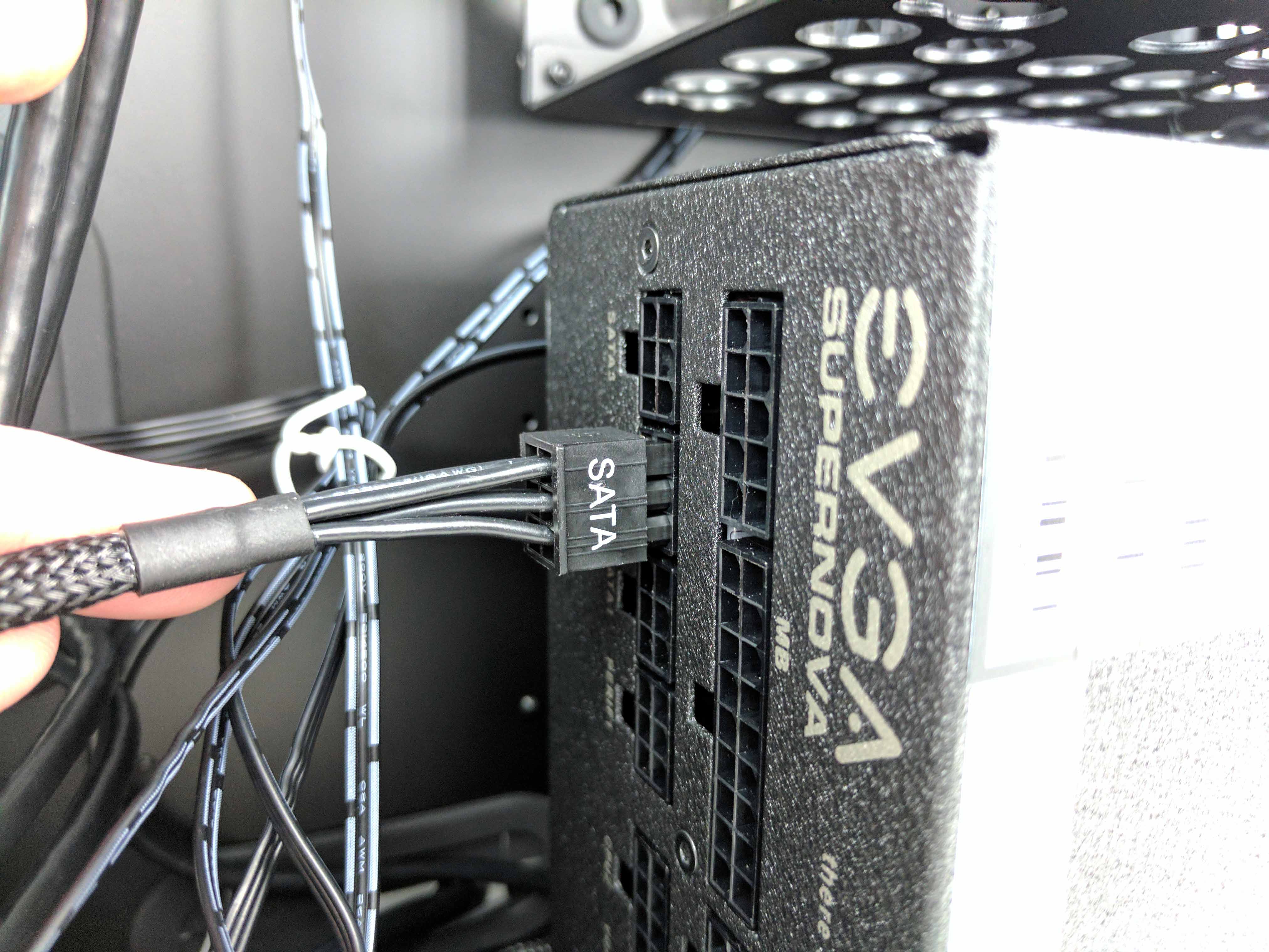
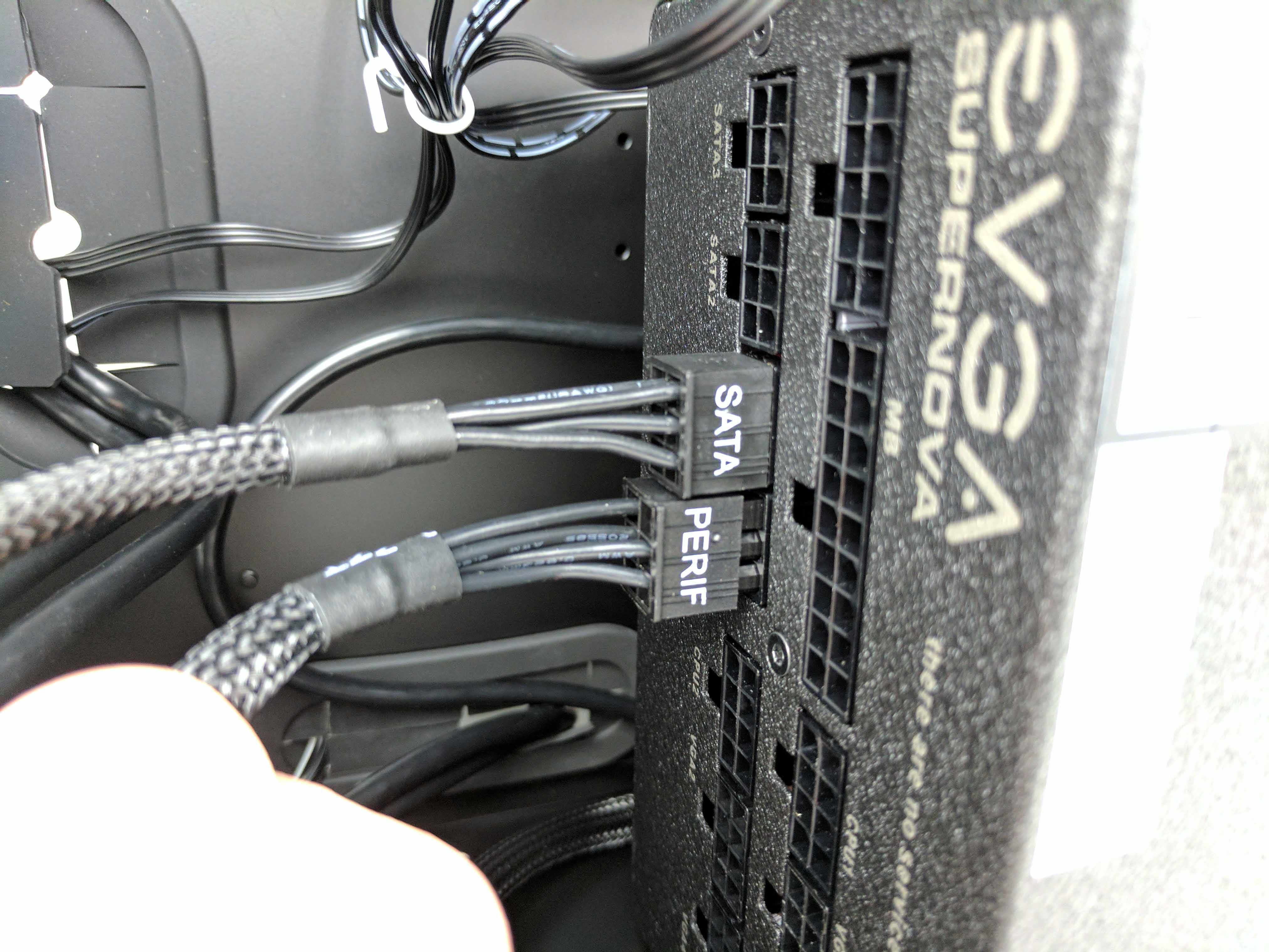
Run the 6-pin side of the cable along the sidewall of the case and out towards you. Let it rest, clear of the PSU landing zone. Line up the power supply to the case’s mounting holes, with the fan facing the motherboard (the solid panel facing you, as seen in the 5th slide in the album above). Slide it into position and secure it to the case with the provided screws. Take the previously installed SATA power plug and connect the 6-pin lead to the PSU in the SATA1 port (last picture in the album above).
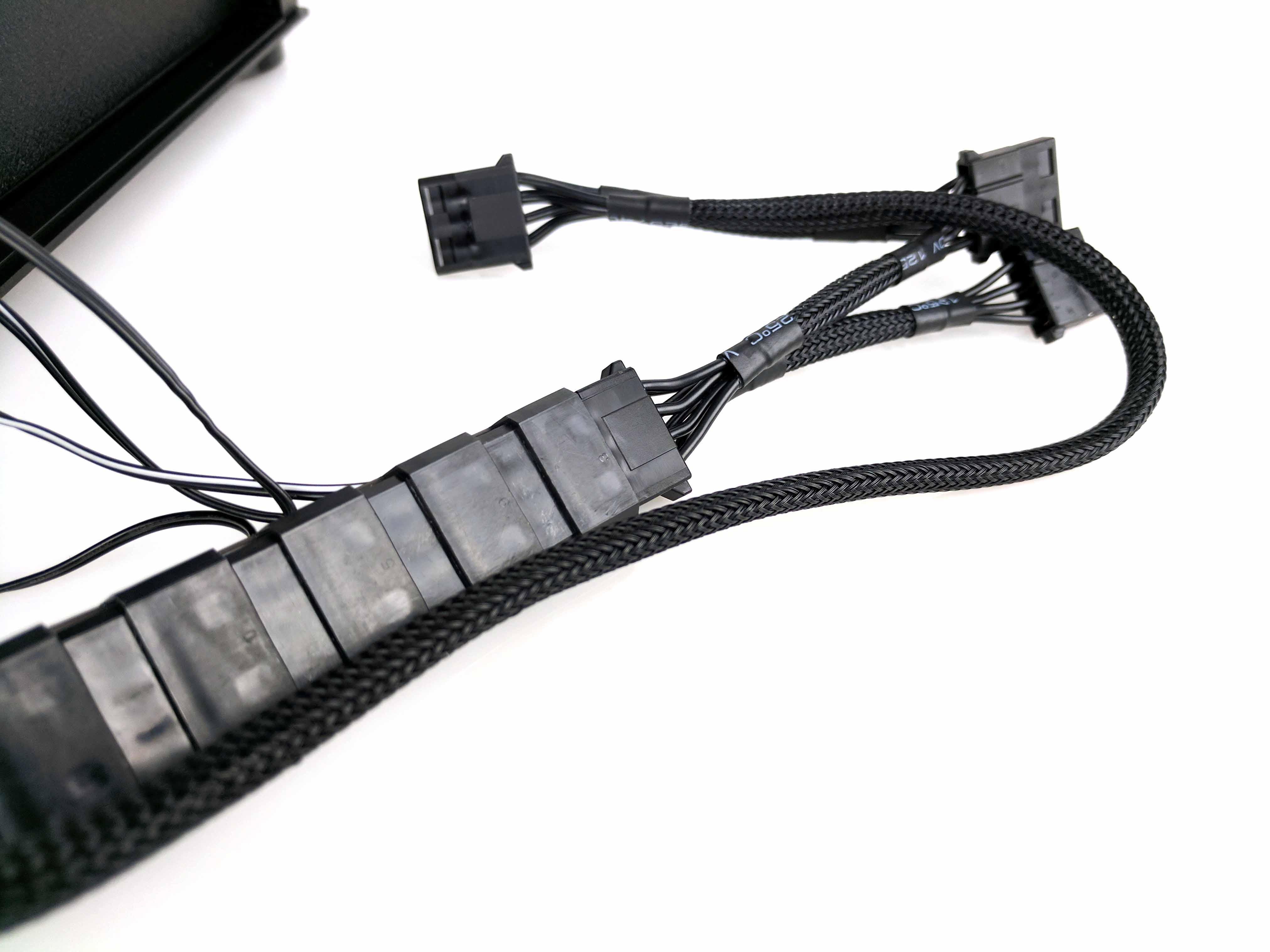
Grab the power cable with the 4-pin molex connectors, labeled “PERIF” (see 1st slide below), and connect the 6-pin lead to the power supply using the corresponding PSU socket (PERIF). Take the bundle of five molex-to-fan adapters (which are resting at the bottom of the case’s drive chamber) and connect it to one of the 4-pin molex connectors from the PERIF cable. Bunch them together as best as possible and use a longer white tie wrap to bundle them together neatly. Tuck the whole batch into the drive bay, clear of the PSU and other cables (and wires we have yet to run).
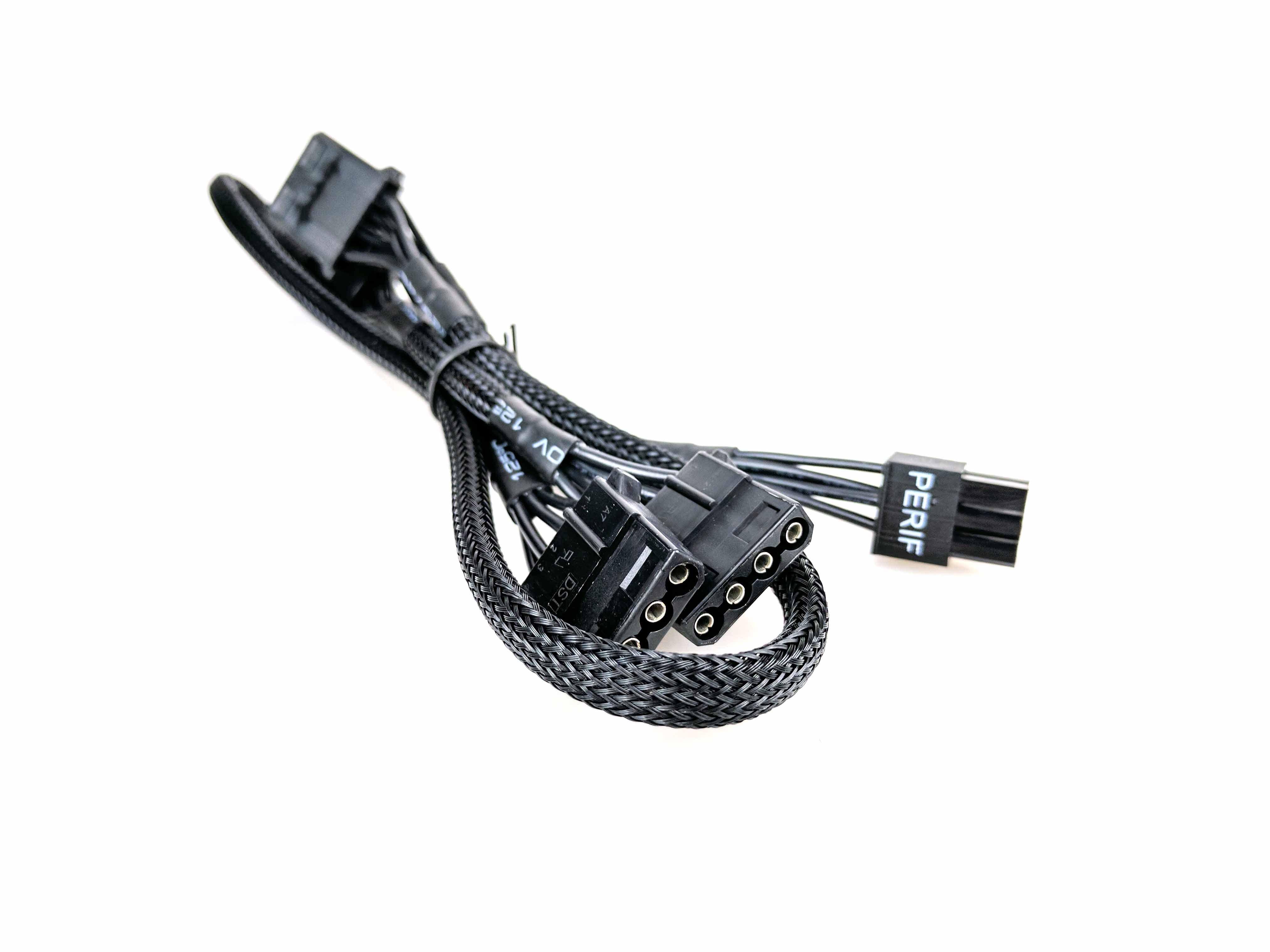
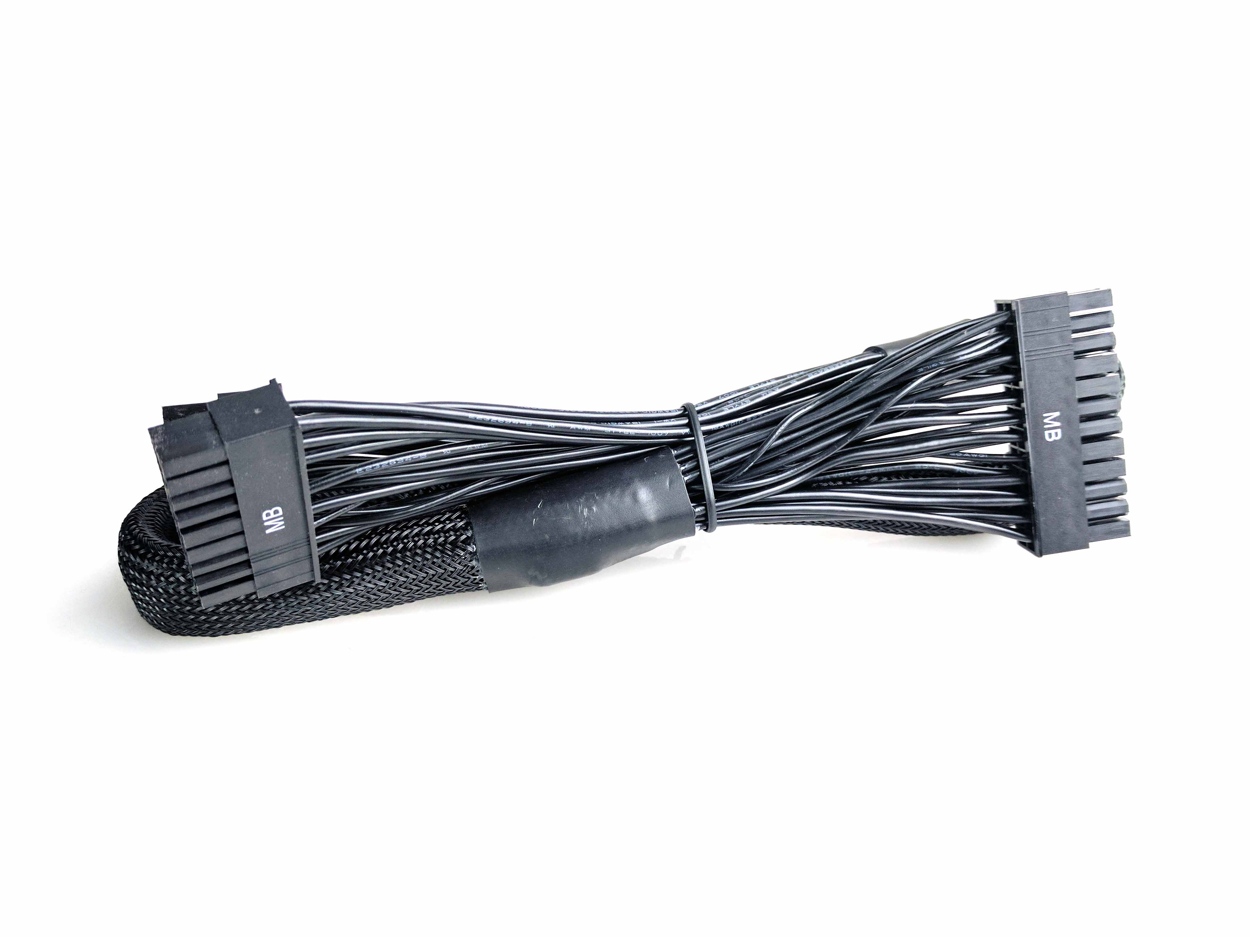
Locate the 24-pin ATX power cable (see slide 1 in the album below). Connect it to the motherboard first and feed the cable into the porthole directly next to the plug. Make it look clean by bending the cables (gently; you don’t want to damage the motherboard) so as little excess possible is visible. Go to the other side of the case (drive chamber) and feed the cable to the PSU, plugging it into the ports labeled “MB” (see final slide below).
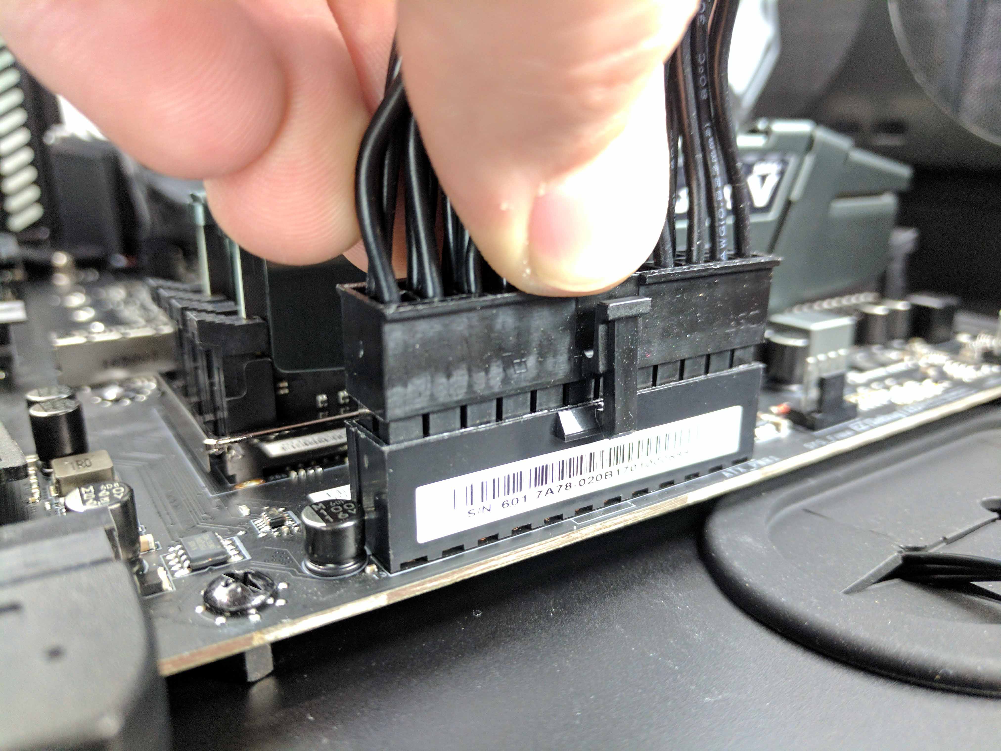
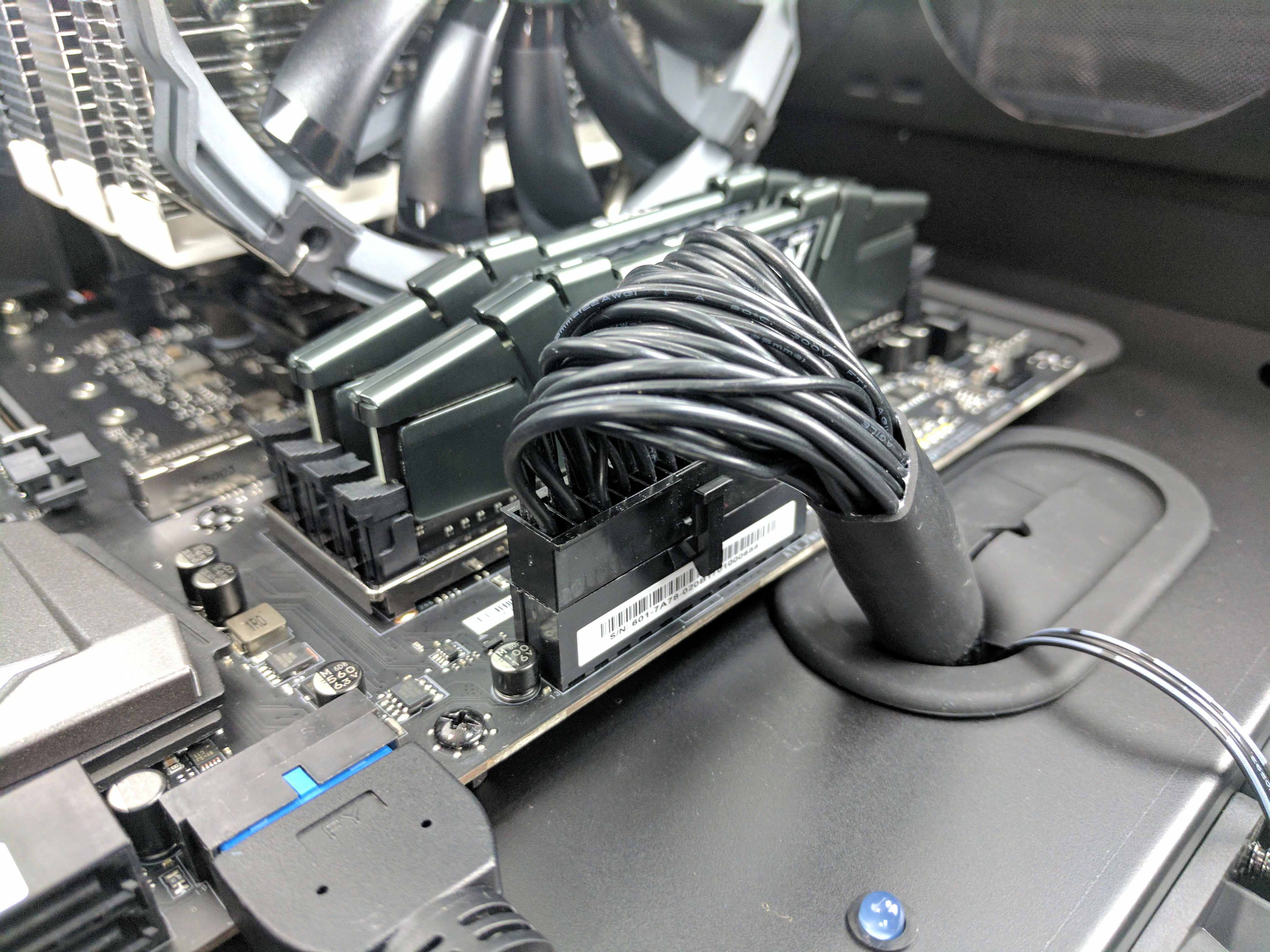
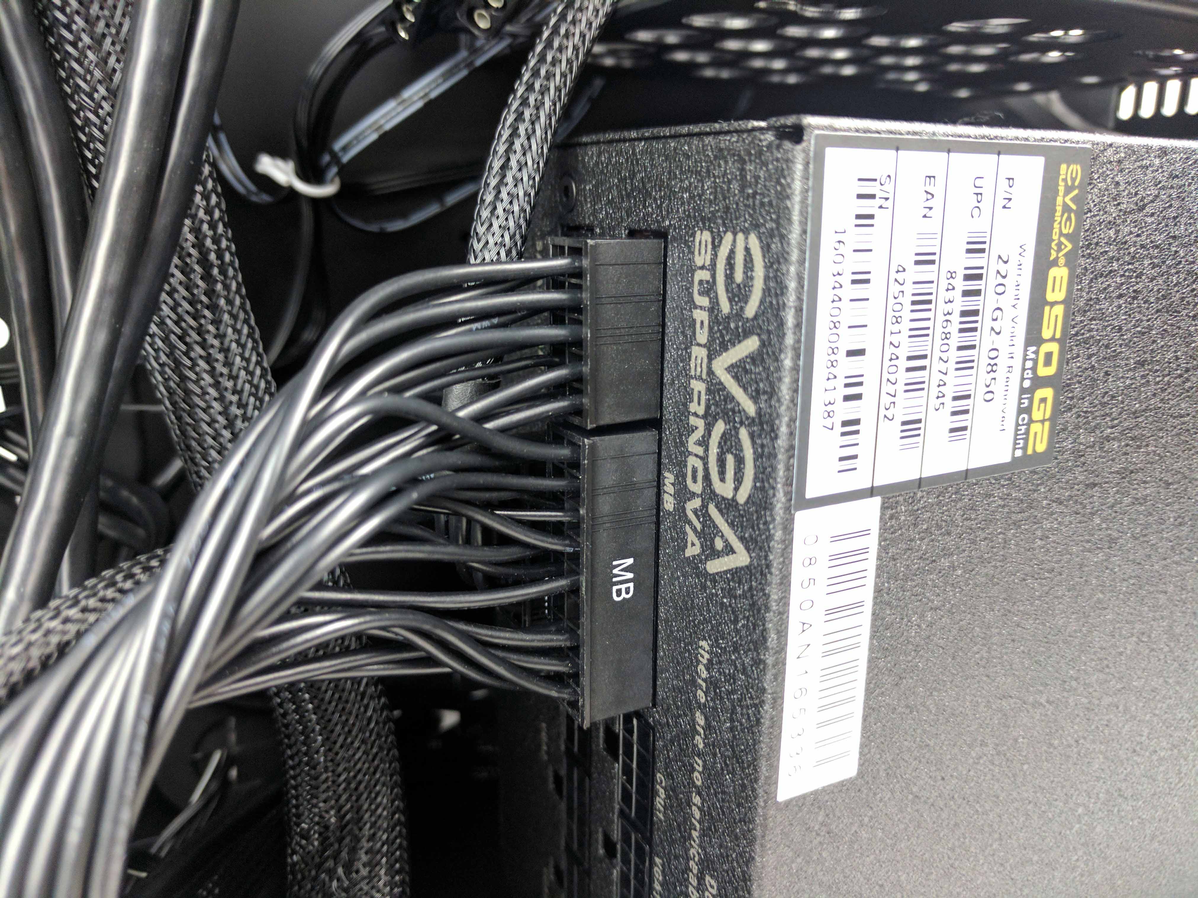
Find the 4+4-pin CPU power cable (slide 1 below), and feed the cable through the hole in the chassis directly above the plug on the motherboard. Connect the 4+4-pin plugs to the 8-pin CPU power socket on the motherboard.
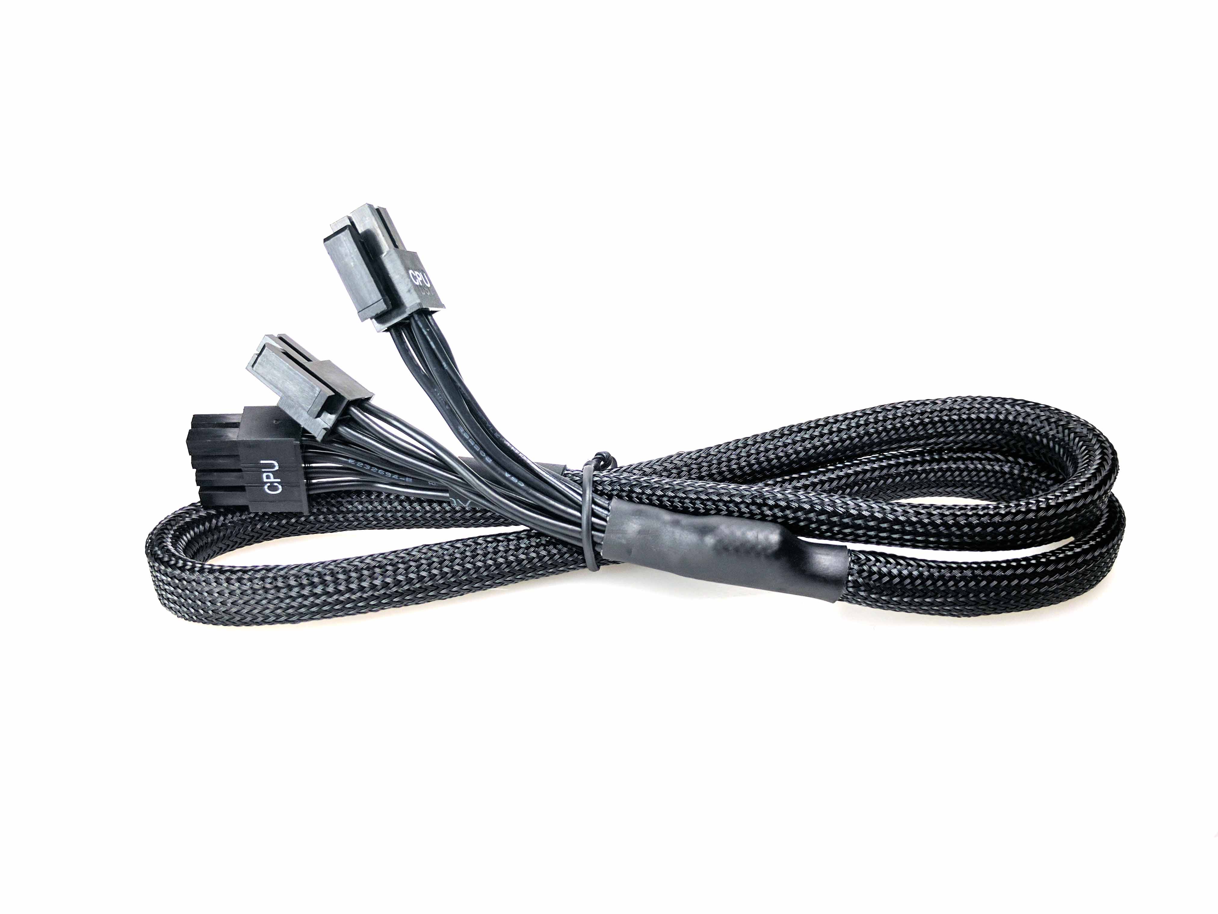
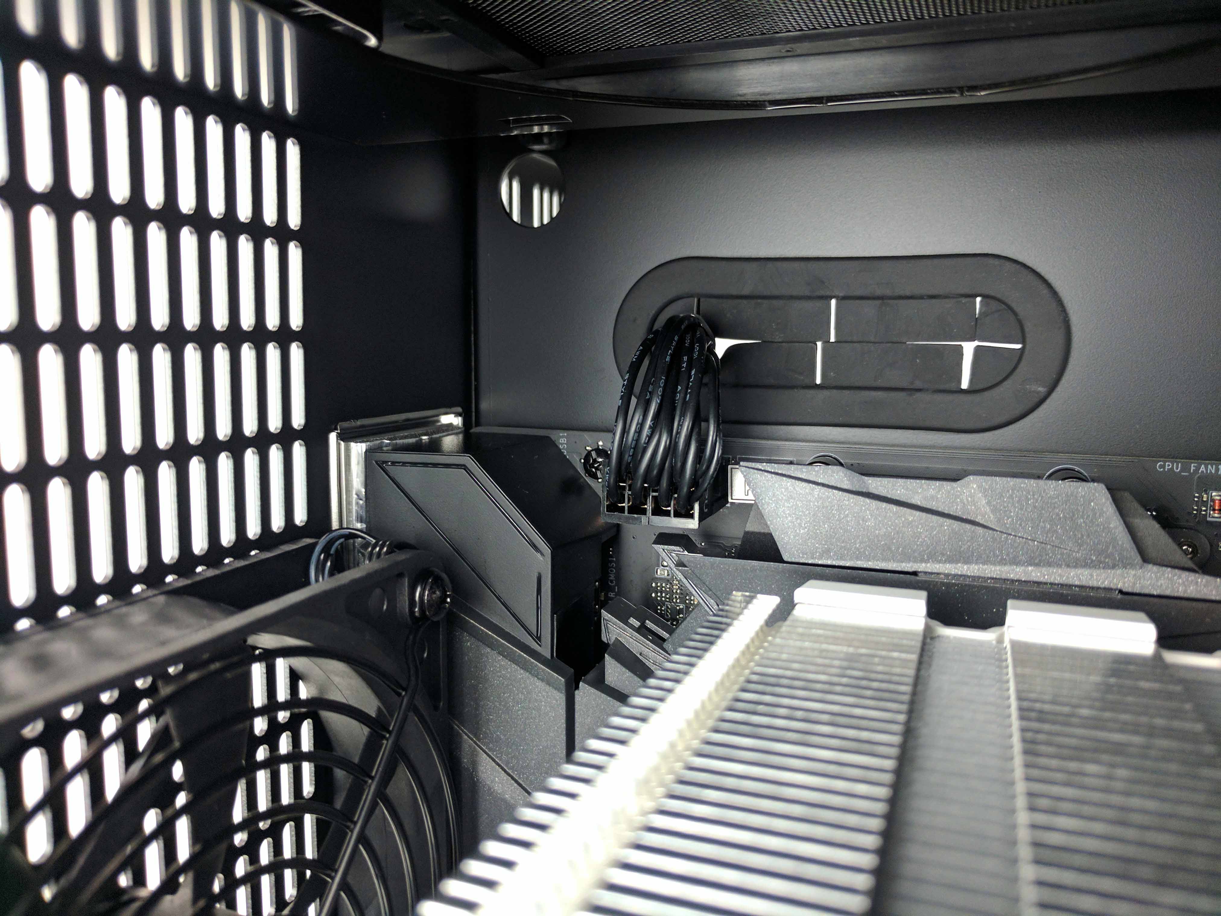
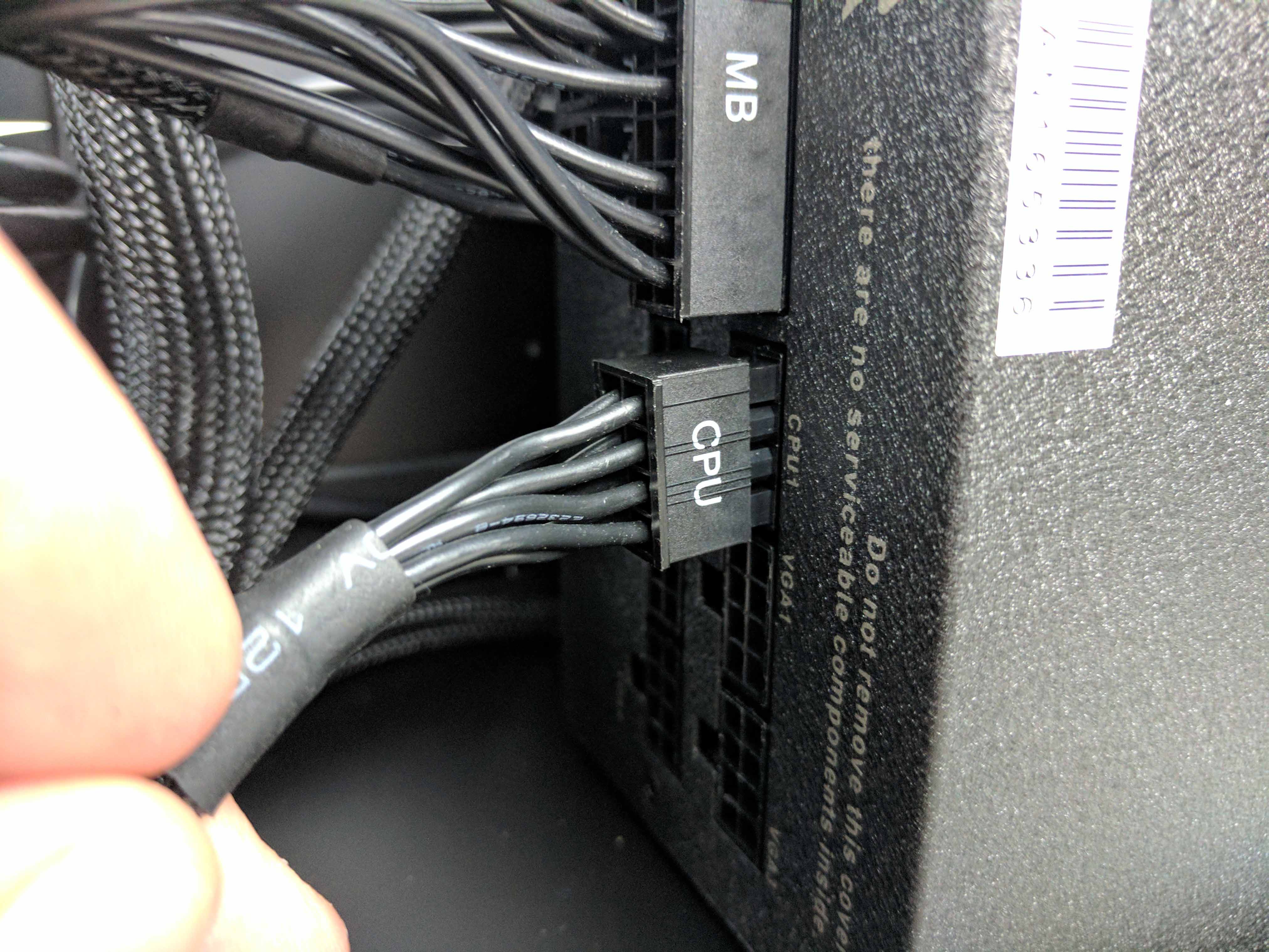
At this point, you may need to remove the drive cage again to properly guide the CPU cable down to the power supply (even if you do, it would only be for a quick moment to grab the CPU cable), but we got lucky and fed it at such an angle that put it directly to the left of the bay where we could easily grab it from the drive chamber. Either way, continue to run the CPU cable down to the PSU, and connect the 8-pin lead to the CPU1 port. If you removed it, replace the drive cage.
The PCIe power cables are all that remain, and the EVGA 850 G2 comes with a few choices for connecting a GPU. Grab the two cables that only have one single 6+2-pin connector on them (see slide 1 in the album below).
Feed the first cable through the bottom vertical porthole in the chassis from the main chamber and into the drive chamber, VGA lead (PSU side) first. Follow suit with the second cable through the same hole. Feed the cables about half way, so that you have slack on both sides (main chamber and drive chamber).
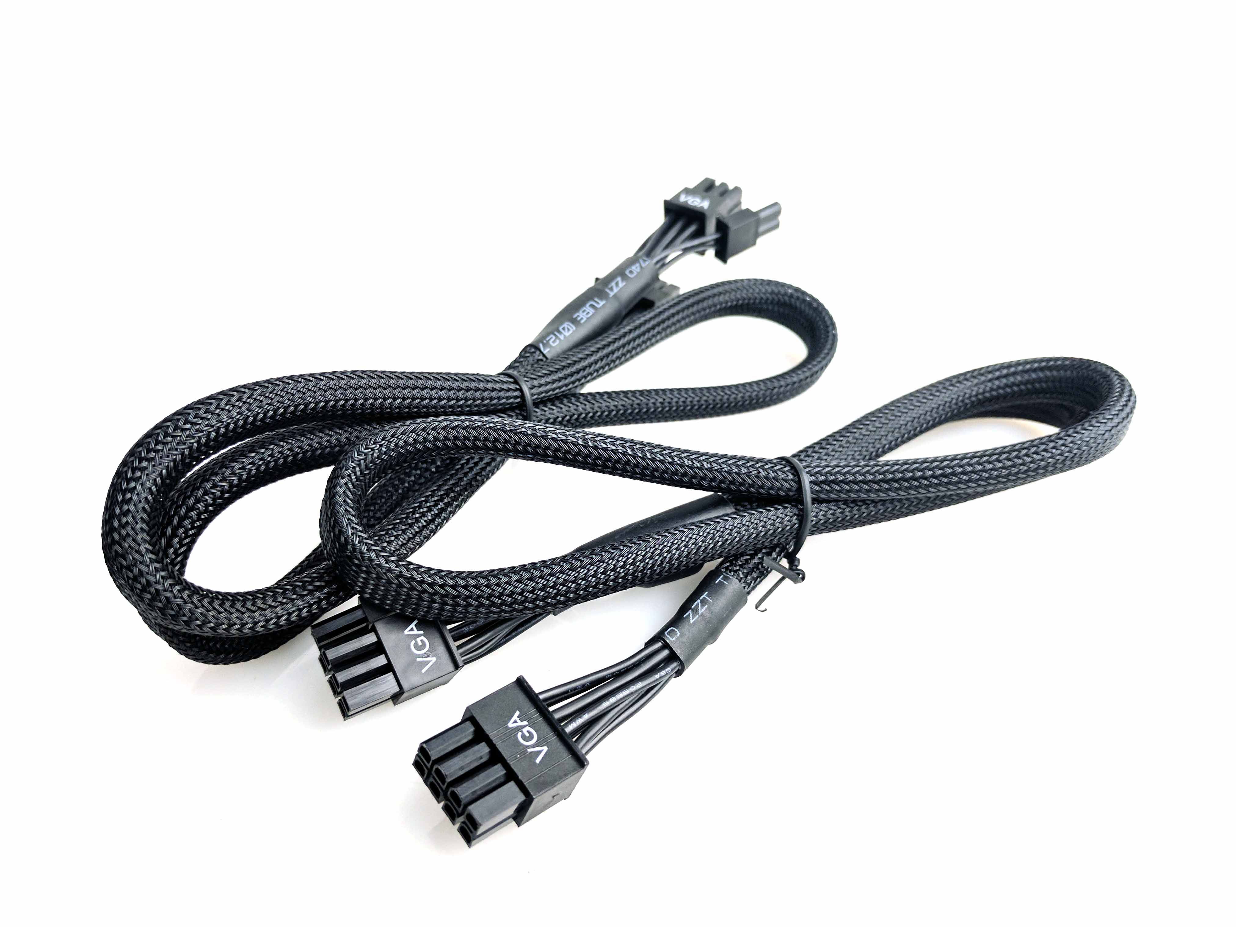
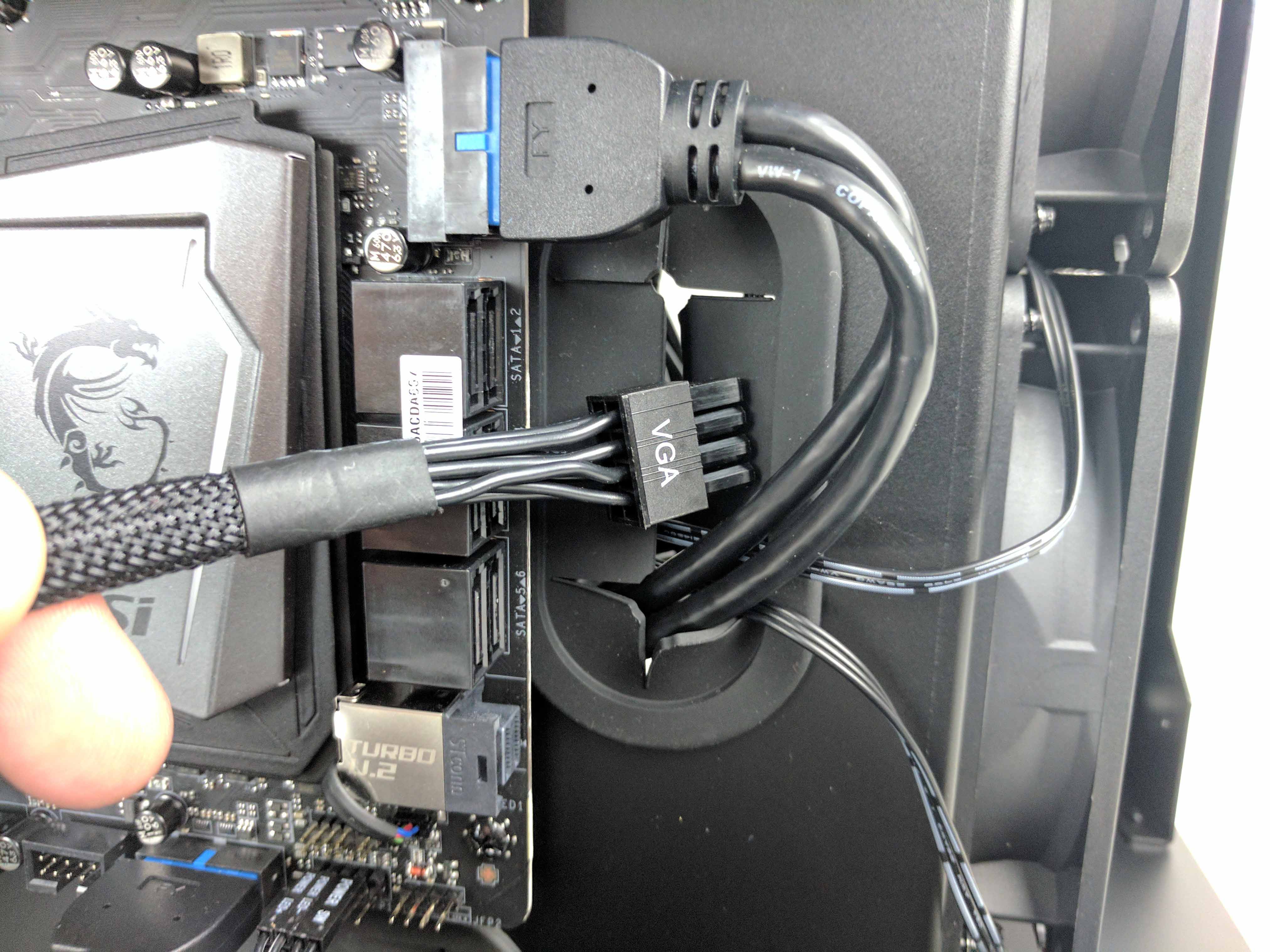
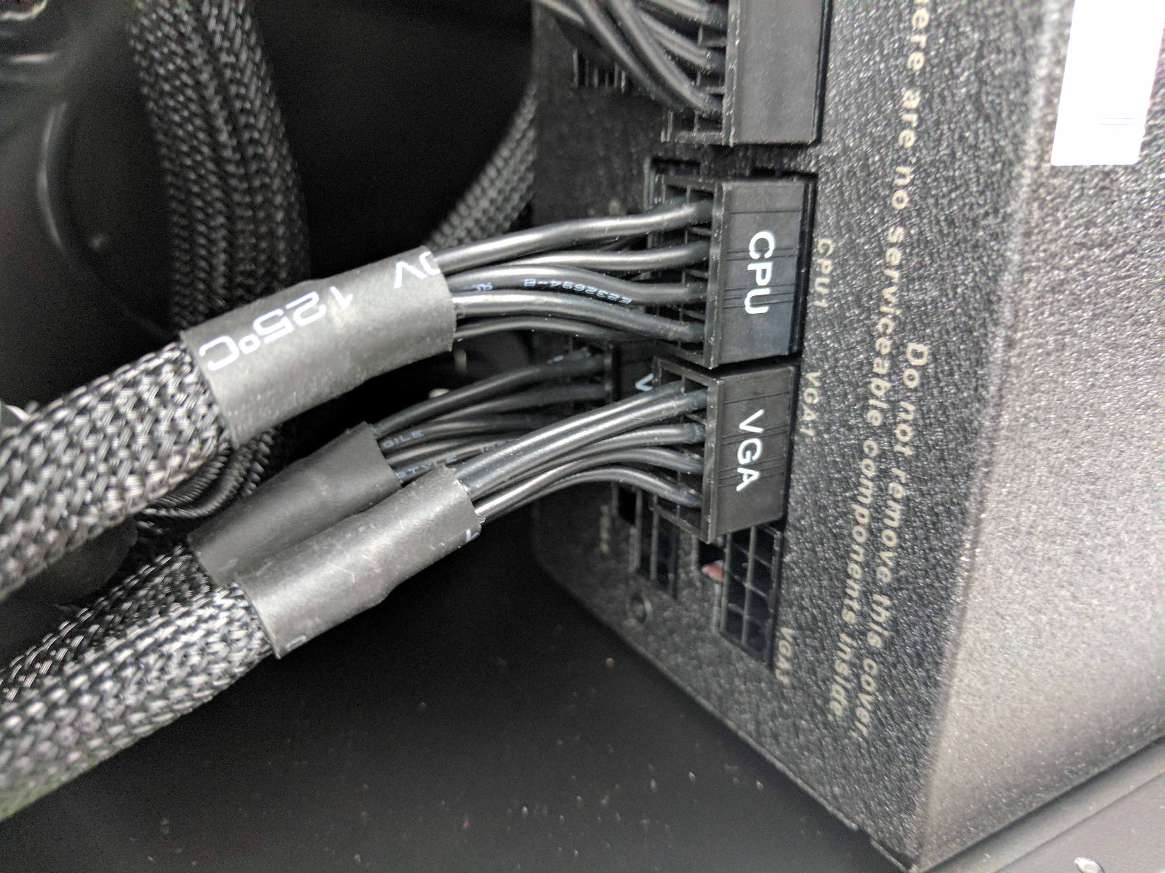
On the drive chamber side of the case, run the cables to the power supply and connect them to the VGA1 and VGA2 slots (start with VGA2 first, it’s behind VGA1) in the PSU. Let the 6+2-pin connectors on the main chamber side hang down (neatly). We’ll need them for the next step.
Graphics
To prepare the case for the graphics cards, unscrew the thumbscrew holding the PCIe slot cover in place. It's located on the rear of the chassis above the PCIe slots on the motherboard. The panel should pull away easily once you remove the thumbscrew (swing it like a door), exposing the individual PCIe slot plates and their thumbscrews.
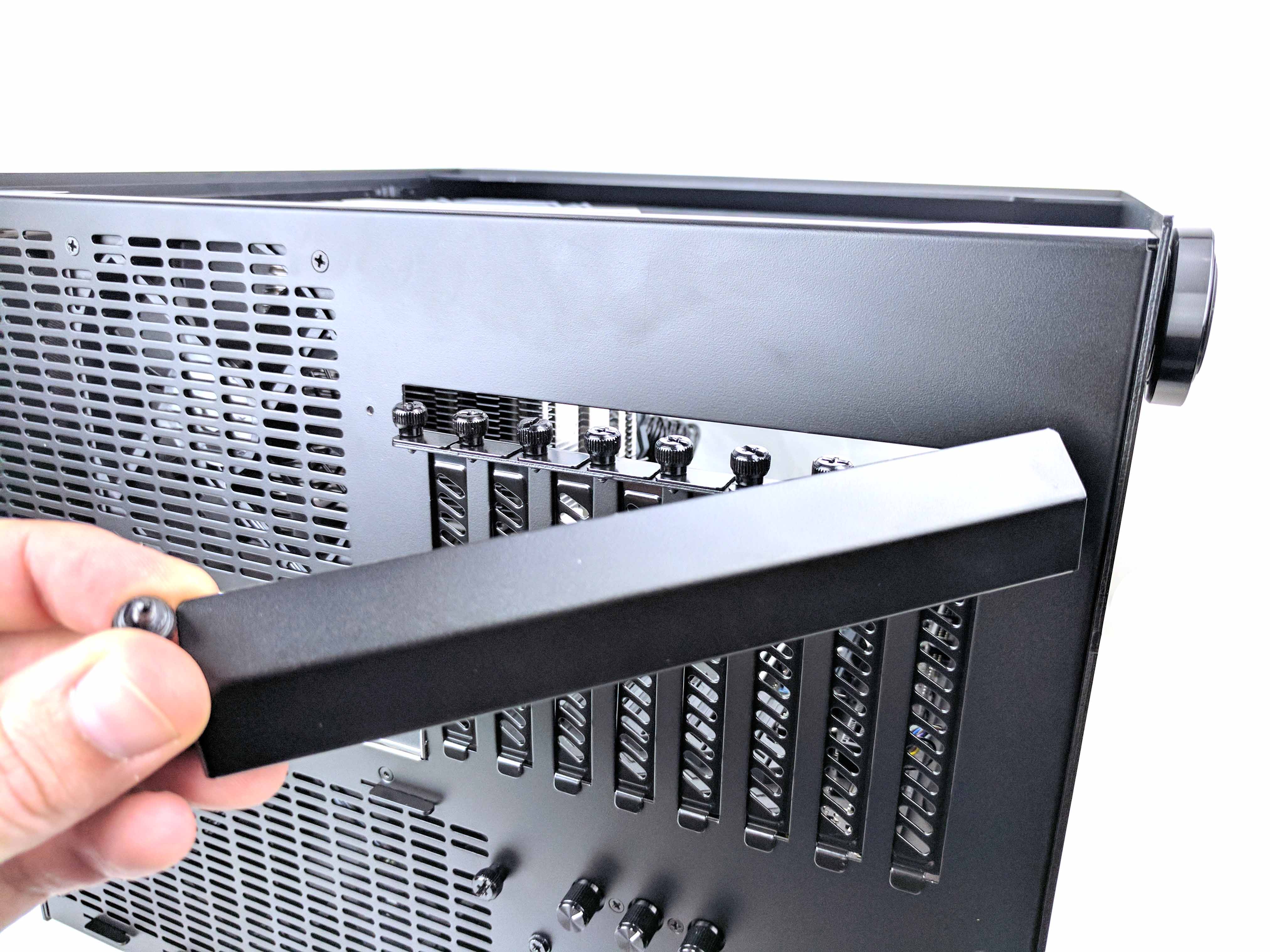
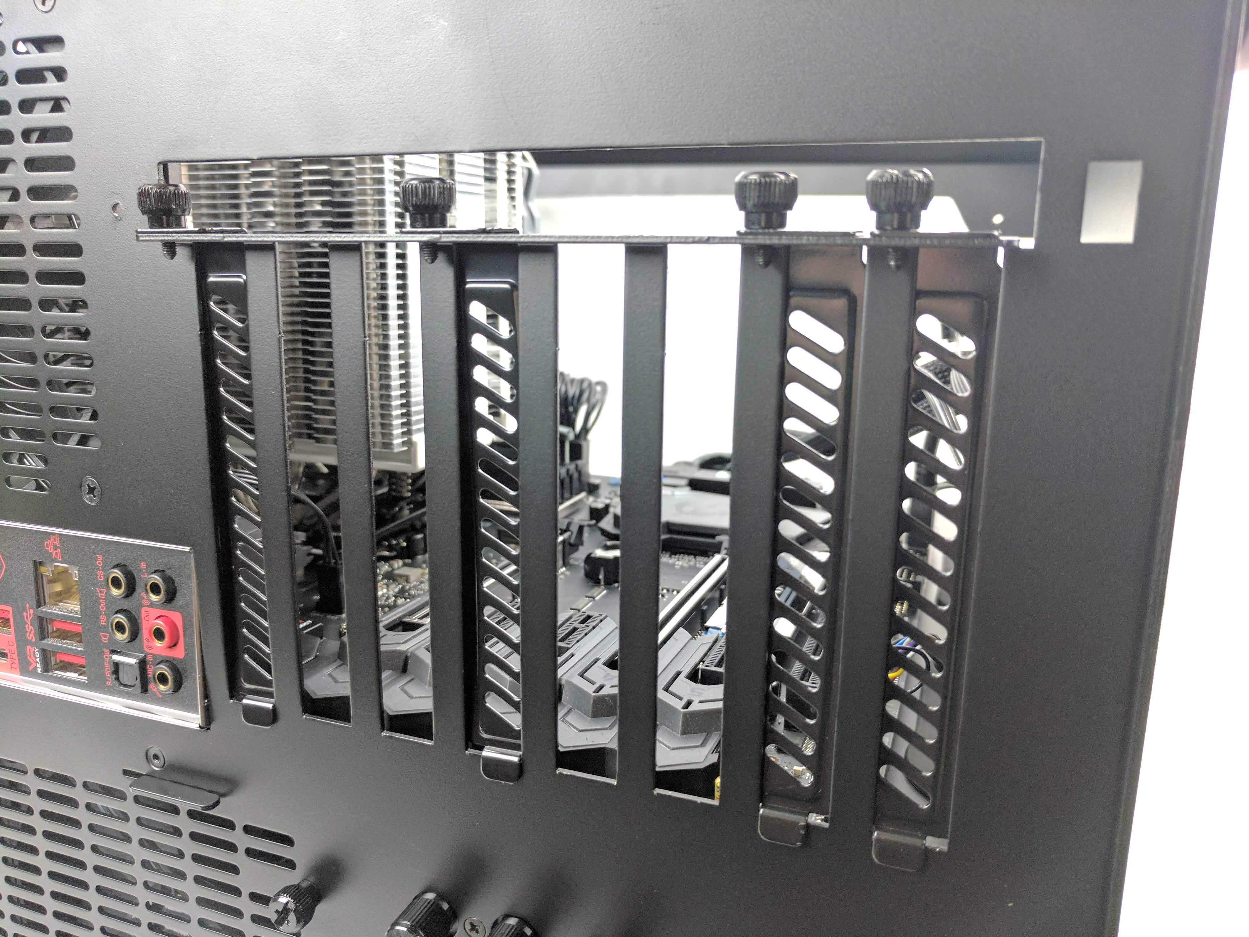
Remove the second, third, fifth and sixth PCIe lane plates (from left to right) by using a screwdriver to loosen and remove the thumb screws, then lift the individual plates up and away from the case.
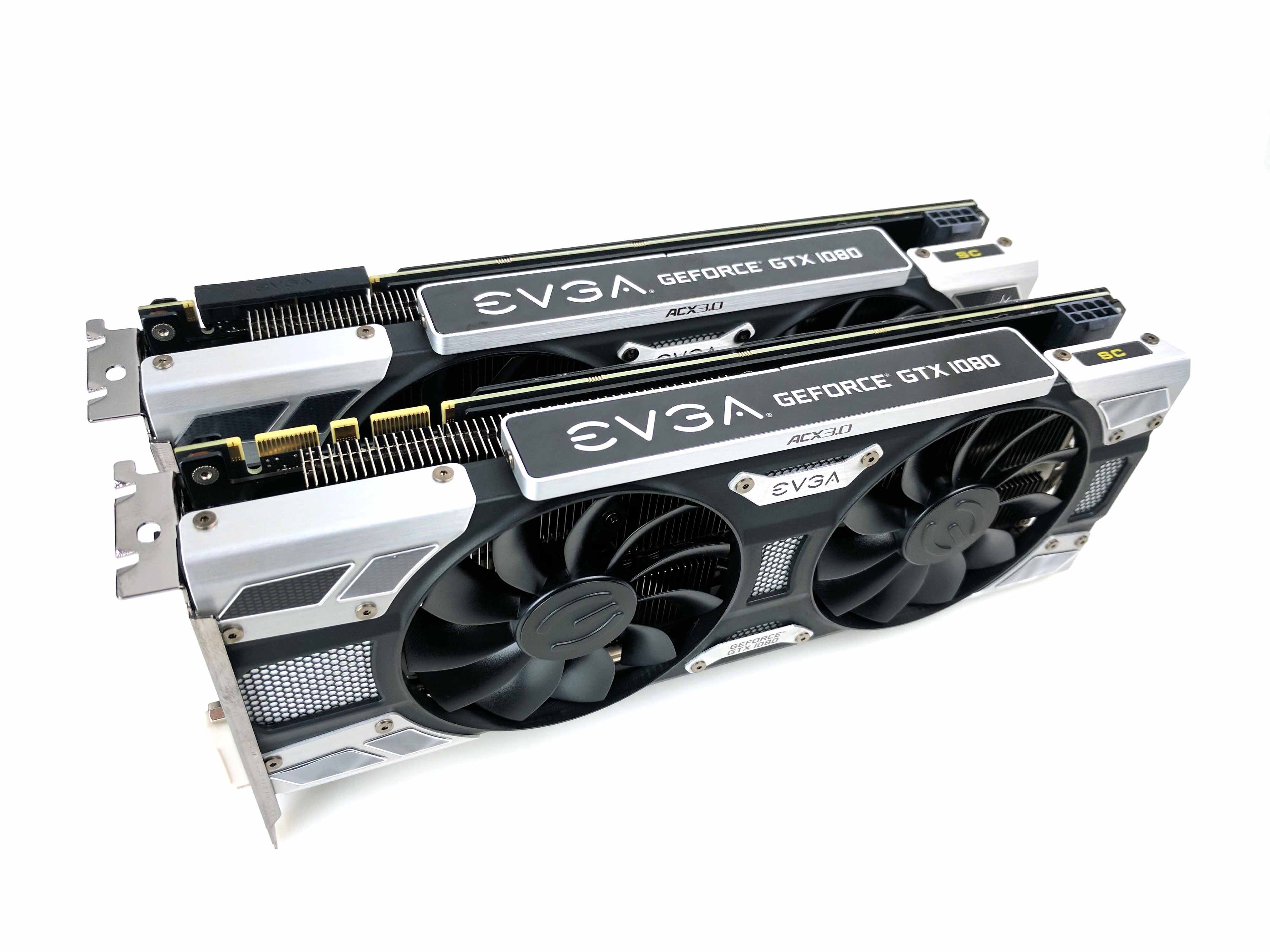
Grab the two EVGA GeForce GTX 1080 8GB ACX 3.0 graphics cards and remove both from their box. Remove all of the protective plastic (EVGA tends to go a bit overboard with this) from the GPU shrouds, fans, and backplate.
Lower the first GPU in the the main chamber of the case, towards the PCIe x16 slot closest to the CPU. Line up the rear I/O plate of the GPU to the appropriate two slots in the case (the second and third), make sure the PCIe connector is lined up with the slot, and push down until the GPU clicks into place. Install the second GPU in the same manner, in the next available PCIe x16 slot on the board. Replace the thumbscrews on the individual PCIe connections to the backplate to secure the GPUs to the chassis.
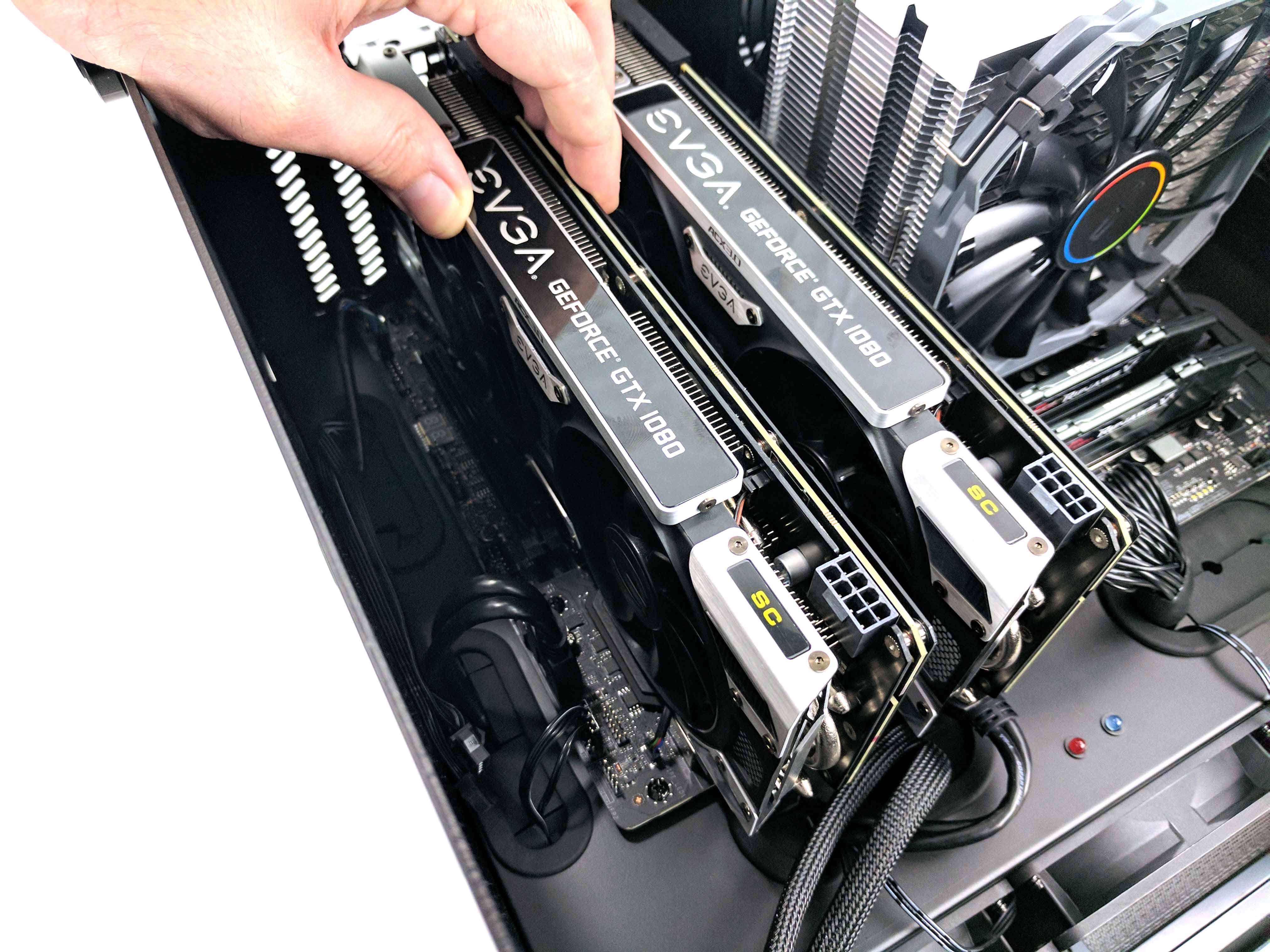
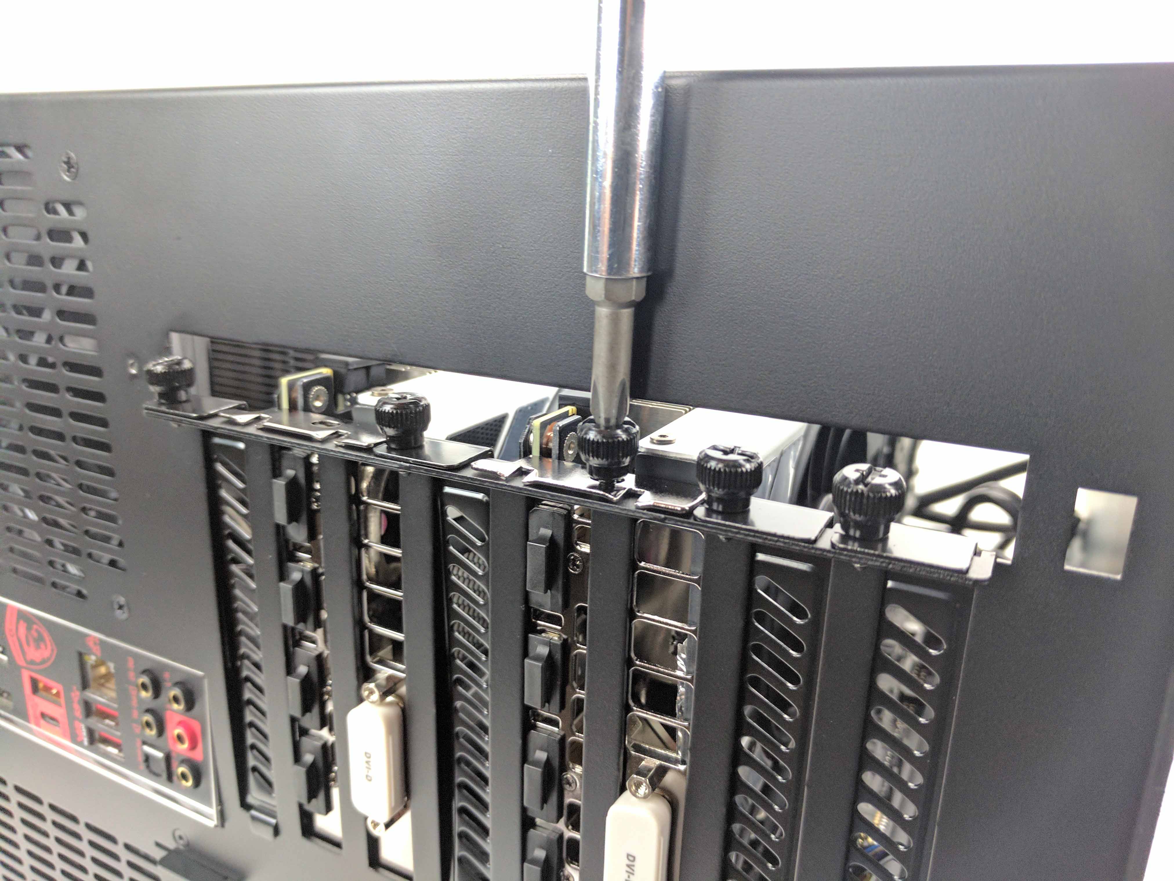
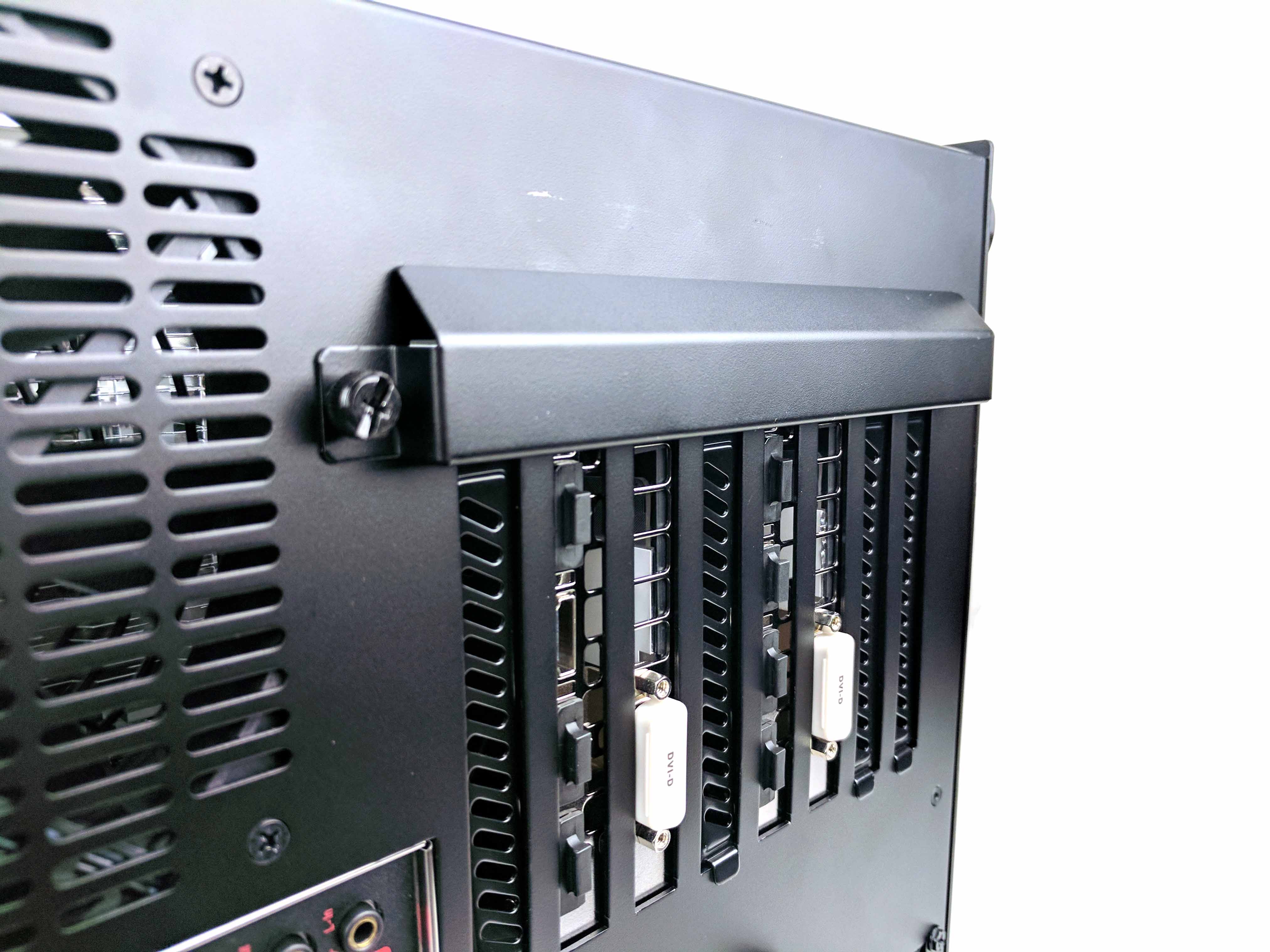
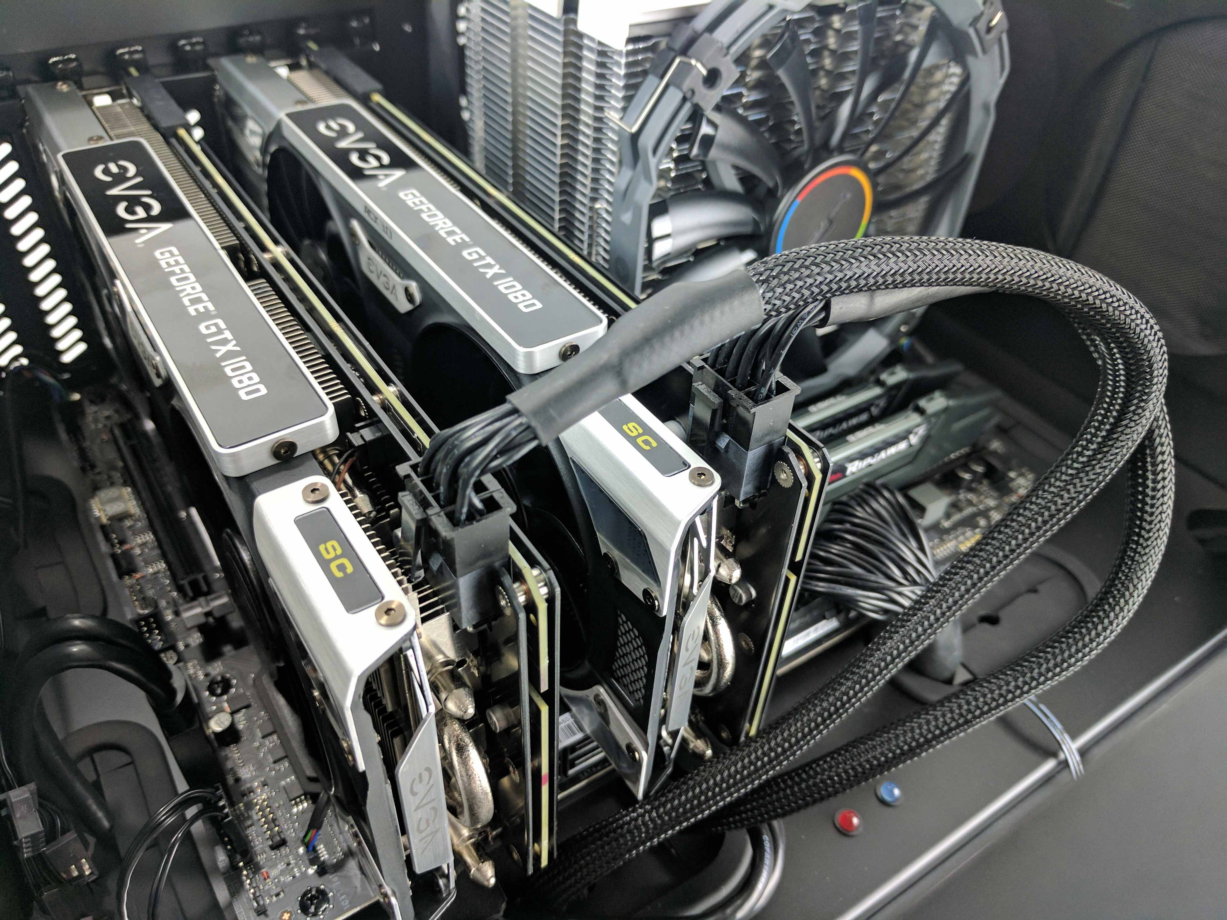
Reattach the rear panel’s PCIe slot cover (hook it into the case then swing it back into place and screw it back into the chassis with the thumbscrew. Go back to the main chamber and connect the PCIe power cables (which are resting at the bottom of the case) to the graphics cards (one at a time, starting with the GPU closest to the CPU). You can adjust the amount of slack exposed in the main chamber by feeding it into the drive chamber.
SLI Bridge
Similar to our Best $2,000 PC Build, the Glass House is an SLI-enabled platform, which requires a high-bandwidth SLI bridge. It’s not uncommon for these to be included with certain high-end motherboards, which is why we were shocked to find that the MSI Z270 Gaming M5 didn’t include any such bridge. You have to purchase one separately, and it was not considered in the budget when g-unit1111 originally designed the Glass House. However, with the recent price drop of the GTX 1080, you won’t have any issue coming in under $2,500, even with the added expense of a high-bandwidth SLI bridge.
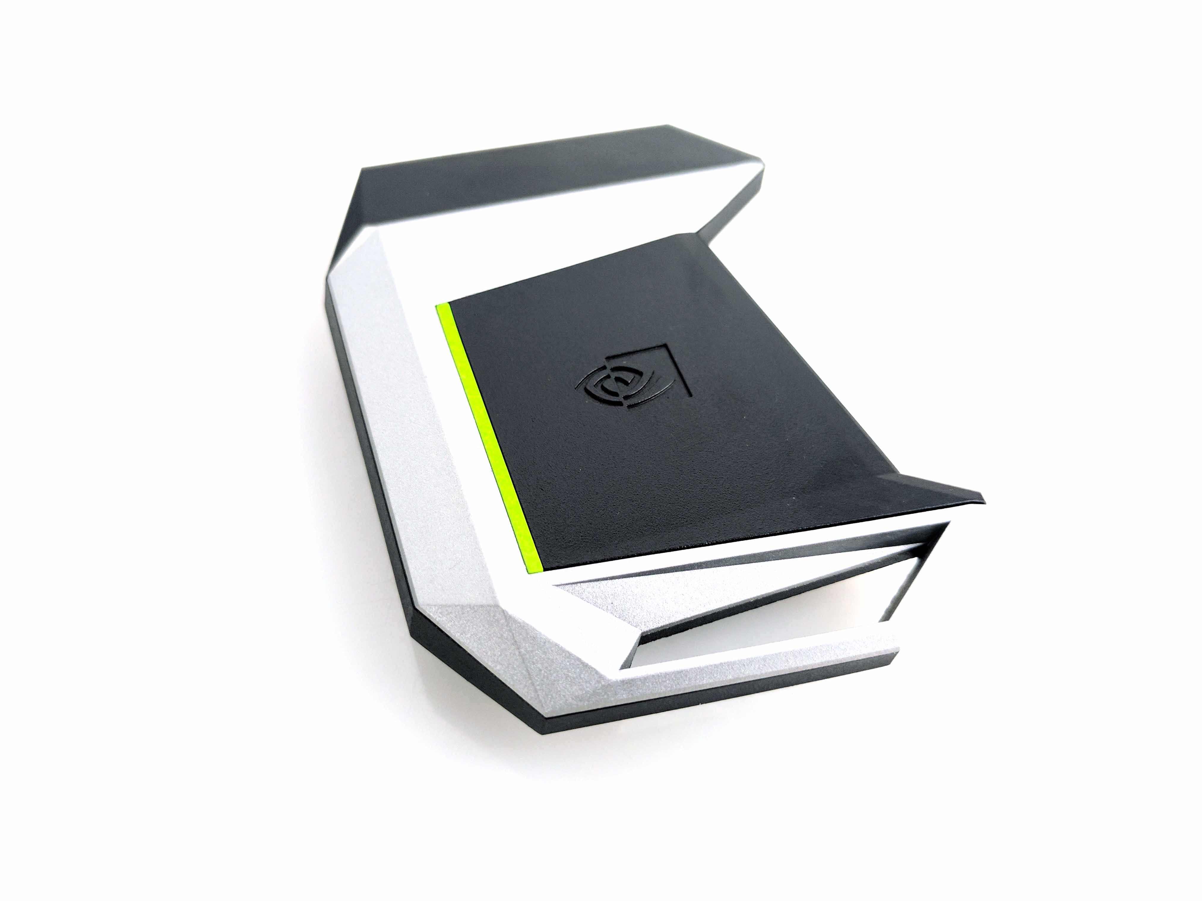
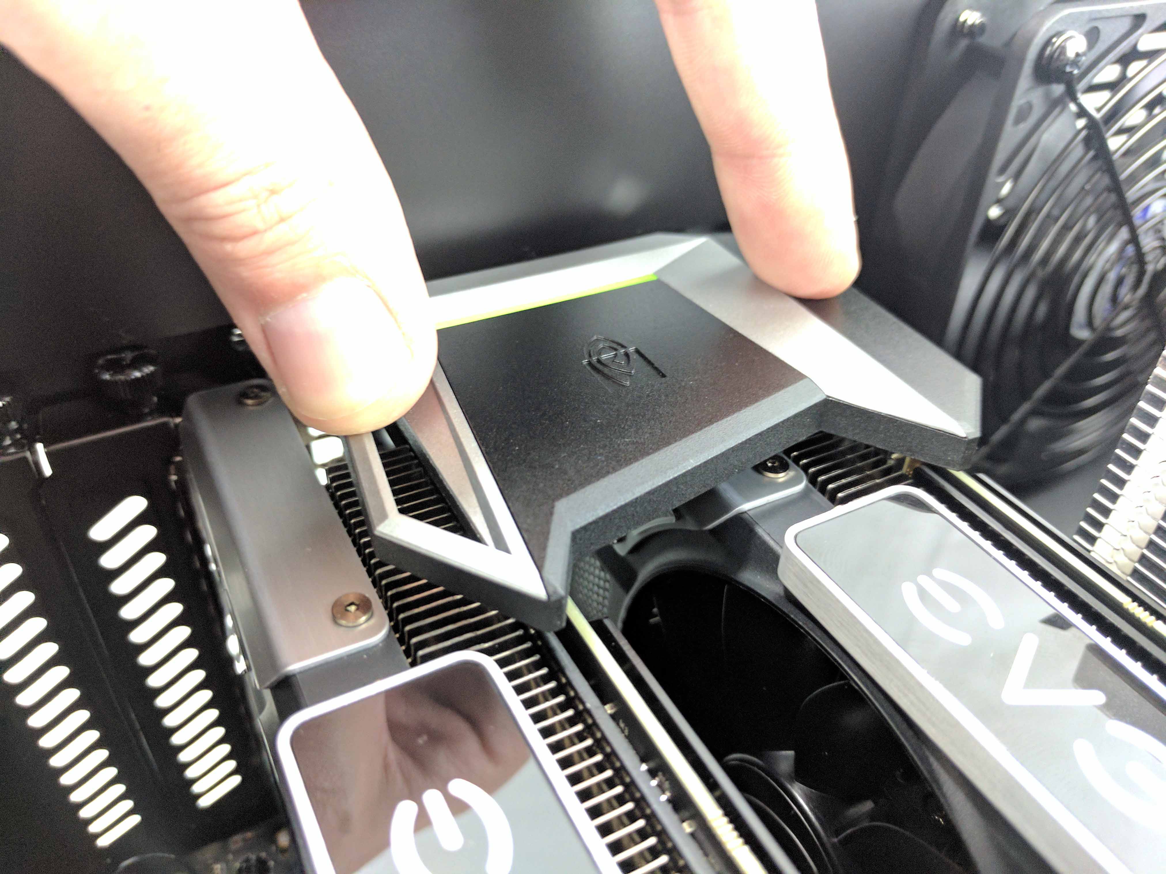
Remove both of the rubber dust covers on the SLI bridge connections of the graphics cards. Take the high-bandwidth SLI bridge out of its package (we opted for an Nvidia-branded bridge) and line it up with the graphics cards. Push down evenly to connect the two graphics cards together.
MORE: Best Deals
MORE: How To Build A PC
MORE: All PC Builds Content
Derek Forrest was a contributing freelance writer for Tom's Hardware. He covered hardware news and reviews, focusing on gaming desktops and laptops.
