High-End P67 Express: Five $200-250 Motherboards
With mainstream boards based on Intel's P67 Express chipset now priced well beyond $150, we reached into the $200-250 range to see what kinds of enhancements high-end buyers could expect just ahead of the anticipated Z68 Express launch.
Overclocking Results
Taking our UEFI screen shots at the top CPU overclock setting meant saving them for last. That’s also when we read the settings for the chart below. By now you’ve probably noticed that MSI’s P67A-GD80 has no UEFI screen shots. Likewise, it didn’t survive to the point where we would have transcribed its adjustment ranges.
| BIOS Frequency and Voltage settings (for overclocking) | |||||
|---|---|---|---|---|---|
| Row 0 - Cell 0 | ASRock Fatal1ty P67 Professional | ASRock P67 Extreme6 | Asus P8P67 Deluxe | Asus P8P67 EVO | MSI P67A-GD80 |
| CPU Base Clock | 95-110 MHz (0.1 MHz) | 95-110 MHz (0.1 MHz) | 80-300 MHz (0.1MHz) | 80-300 MHz (0.1MHz) | Row 1 - Cell 5 |
| CPU Multiplier | Up to 60x | Up to 60x | Up to 59x | Up to 59x | Row 2 - Cell 5 |
| DRAM Data Rates | 1066-2133 (266.6 MHz) | 1066-2133 (266.6 MHz) | 800-2400 (266.6 MHz) | 800-2400 (266.6 MHz) | Row 3 - Cell 5 |
| CPU Vcore | 0.60-1.52V (5mV) | 0.60-1.70V (5mV) | 0.80-1.99V (5mV) | 0.80-1.99V (5mV) | Row 4 - Cell 5 |
| VTT Voltage | 0.66-1.87 (13mV) | 0.66-1.87 (13mV) | 0.80-1.70V (6.25mV) | 0.80-1.70V (6.25mV) | Row 5 - Cell 5 |
| PCH Voltage | 0.78-1.65V (9mV) | 0.78-1.65V (9mV) | 0.80-1.70V (10mV) | 0.80-1.70V (10mV) | Row 6 - Cell 5 |
| DRAM Voltage | 1.20-1.80V (15mV) | 1.20-1.80V (15mV) | 1.20-2.20V (6.25mV) | 1.20-2.20V (6.25mV) | Row 7 - Cell 5 |
| CAS Latency | 5-15 Cycles | 5-15 Cycles | 3-15 Cycles | 3-15 Cycles | Row 8 - Cell 5 |
| tRCD | 4-15 Cycles | 4-15 Cycles | 4-15 Cycles | 4-15 Cycles | Row 9 - Cell 5 |
| tRP | 4-15 Cycles | 4-15 Cycles | 4-15 Cycles | 4-15 Cycles | Row 10 - Cell 5 |
| tRAS | 10-40 Cycles | 10-40 Cycles | 4-40 Cycles | 4-40 Cycles | Row 11 - Cell 5 |
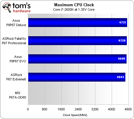
The P8P67 Deluxe leads in CPU overclocking, though the Fatal1ty P67 Professional is not far behind. MSI wasn't able to participate in this test, unfortunately, as its board met an early demise.
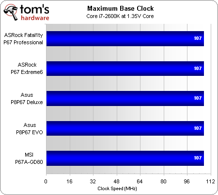
MSI did participate in the base clock test, where all motherboards successfully pushed their P67 platform controller hubs to 107 MHz. So, where did the MSI motherboard fail?
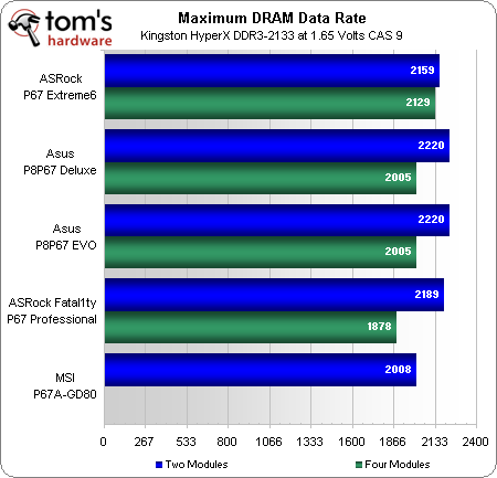
The P67A-GD80 refused to cold boot following its memory stability test at DDR3-2008, instead power cycling in one to two-second intervals. Further analysis indicated that this was due to a bad UEFI setting that stuck. Neither the button on the I/O panel nor the jumper on the motherboard’s surface cleared the problem, even after battery removal.
Another method to get BIOS to revert to safe settings is to force a hardware configuration error, yet swapping out components did not work either. When stuck, the P67A-GD80 wouldn't even register a memory or graphics error with those parts removed. Hopes that MSI’s backup ROM on this Dual BIOS-equipped motherboard might have initialized itself turned to hopelessness. One of our engineering friends said that the reboot was occurring before system logic could register the error, because the error was occurring at the wrong part of the initialization process. In all likelihood, this really was an old-fashioned "stuck BIOS” issue.
MSI’s P67A-GD80 has two ROM ICs, but no selector switch to force a boot from the second ROM. It also lacks a removable ROM socket, so hot-flashing it by using another motherboard was not an option. This might just be one configuration where a removable single BIOS ROM would have been more valuable than two soldered-on BIOS ICs.
Get Tom's Hardware's best news and in-depth reviews, straight to your inbox.
Current page: Overclocking Results
Prev Page Benchmark Results: Productivity Next Page Power And Efficiency-
joytech22 So glad I grabbed my P8P67 Deluxe!Reply
It had all the features I was looking for at a low enough price to make it very appealing. -
Crashman rolli59Nice article would have been nice to have a Gigabyte board in there as well.Please tell Gigabyte to produce something for this market!Reply
Tom's Hardware included the UD4 in its $150-200 motherboard roundup, and the UD5 costs more than $250. -
Manos How te hell is it possible that a website like this keeps ignoring my question as in WHY its been for so many months if not year or whatever, that they dont fix this *** and I cant click to submit my comment from IE? How can THIS be the only website with issues with IE? I find it rather sad. Its why i quit commenting instead of being forced to open a different browser for this site which I used to love and respect. Till they started ignoring this issue Ive been pointing out ( and not just me ).Reply
Thank you for the charts tho id love to see one with Maximus IV included x.x ( I edited cause I asked something stupid as in why I dont see it in the chart. Sorry.. Been working all night and no time to read the article. Bits only.And no I obviously hadnt read the title x.x My bad. Happy Easter! -
jerreddredd It would have been nice to see if there is a performance gain in these "high end" boards over a value P67 board.Reply
For an even better article also throw in one of each value rated H67 and H61 boards. ($240 vs $130 vs $70 boards)
-
alidan jerreddreddIt would have been nice to see if there is a performance gain in these "high end" boards over a value P67 board. For an even better article also throw in one of each value rated H67 and H61 boards. ($240 vs $130 vs $70 boards)this, i would love to see how the high end stacks up with the low end. the low may not have as much as the high end, but performance is really all that matters considering we can just get expansion cards for things we dont have.Reply -
Hupiscratch Great article. Now it´s time for the high-end overclocking oriented boards, like the ASUS Maximus IV Extreme.Reply -
memadmax I'm gonna go all out on this chipset when it matures a bit. A cool 5 grand i'm thinking for my next gen build.Reply


