Corsair AX1600i PSU Review
Why you can trust Tom's Hardware
Teardown & Component Analysis
Before proceeding with this page we strongly encourage you to a look at our PSUs 101 article, which provides valuable information about PSUs and their operation, allowing you to better understand the components we're about to discuss. Our main tools for disassembling PSUs are a Thermaltronics soldering and rework station and a Hakko FR-300 desoldering gun. Finally, for the identification of tiny parts we use an Andonstar HDMI digital microscope.
| General Data | |
|---|---|
| Manufacturer (OEM) | Flextronics |
| Platform Model | Churchill (probably) |
| Primary Side | |
| Transient Filter | 6x Y caps, 2x X caps, 3x CM chokes, 1x DM choke, 1x MOV, 1x CAP200DG |
| Inrush Protection | 2x NTC Thermistor & 1x Relay |
| Rectifier Diodes (Standby Mode) | 4x S8KC (800V, 8A @ 75°C) |
| Totem-Pole PFC MODFETs (HEMTs) | 4x Transphorm TPH3205WSB (650V, 22A @ 100°C, 60mΩ) |
| Totem-Pole PFC Driver | 1x STMicroelectronics PM8834, 2x Silicon Labs Si8233AB |
| Totem-pole PFC MOSFETs | 2x Toshiba TK62J60W (600V, 61.8A @ 150°C, 33mΩ) |
| Totem-pole PFC MOSFET Driver | 1x Fairchild FAN73933 |
| Hold-up Cap(s) | 1x Rubycon (450V, 680uF, 3000h @ 105°C, MXK) 2x Nippon Chemi-Con (450V, 470uF, 2000h @ 105°C, KMW) |
| Main Switchers | 4x 60F2094 |
| Driver ICs | 2x Silicon Labs Si8233BD |
| Topology | Primary side: Totem-Pole Bridgeless PFC, Full-Bridge & LLC Resonant Controller Secondary side: Synchronous Rectification & DC-DC converters |
| Digital Control Board | |
| Primary DSC | Texas Instruments UCD3138064A |
| Secondary DSC | NXP Freescale MC56F8236 |
| MCU | Silicon Lab C8051F380 (USB 2.0 controller) |
| Quadruple Op. Amps | 5x Texas Instruments L2902KA |
| Quad Differential Comparator | 2x Texas Instruments LM239A |
| Secondary Side | |
| +12V FETs | 16x Infineon BSC028N06NS (60V, 83A @ 100°C, 2.8mΩ) FETs, 2x STMicroelectronics PM8834 drivers |
| +12V Driver ICs | 2x STMicroelectronics PM8834 drivers |
| 5V & 3.3V | DC-DC Converters: 8x ON Semiconductor NTMFS4C06N (30V, 14.9A @ 80°C, 6mΩ) PWM Controller: NCP1034DG |
| Filtering Capacitors | Electrolytics: United Chemi-Con (1-5000h @ 105°C, KZE), United Chemi-Con (4-10,000h @ 105°C, KY), United Chemi-Con (2-8000h @ 105°C, LXZ), United Chemi-Con (1-2000h @ 105°C, KMQ), United Chemi-Con (5-6000h @ 105°C, KZH) Polymers: United Chemi-Con, FPCAP |
| Fan Model | NR140P (140mm, 12V, 0.22A, Fluid Dynamic Bearing) |
| 5VSB Circuit | |
| Rectifier | 1x 9R1K2C (900V, 3.2A @ 100°C, 1.2Ω) |
| Standby PWM Controller | Infineon ICE3BS03LJG |
| Modular PCB | |
| Rectifiers | 1x SK34A SBR (40V, 3A), 2x NTMFS4C03N (30V, 136A @ 25°C, 2.8mΩ) |
| Filtering Capacitors | Electrolytics: 8x United Chemi-Con (6-10,000h @ 105°C, KZM), 2x United Chemi-Con (1-2000h @ 105°C, KMQ) Polymers: 13x United Chemi-Con |
We say that this platform is probably named "Churchill" because we found the famous surname written in several places on the main PCB and its daughterboards.
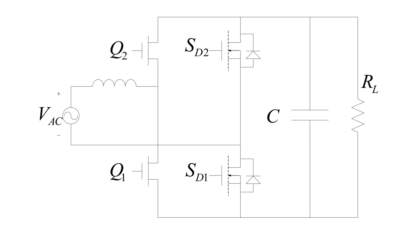
There are currently no commercial analog controllers available for a totem-pole PFC, so this design is only possible through a digital controller due to its flexible nature. In general, controlling a totem-pole PFC is much more difficult than a traditional APFC converter. The lack of bridge rectifiers, the bidirectional inductor current, and the function swap between main and sync switches are some of the challenges that engineers have to face.
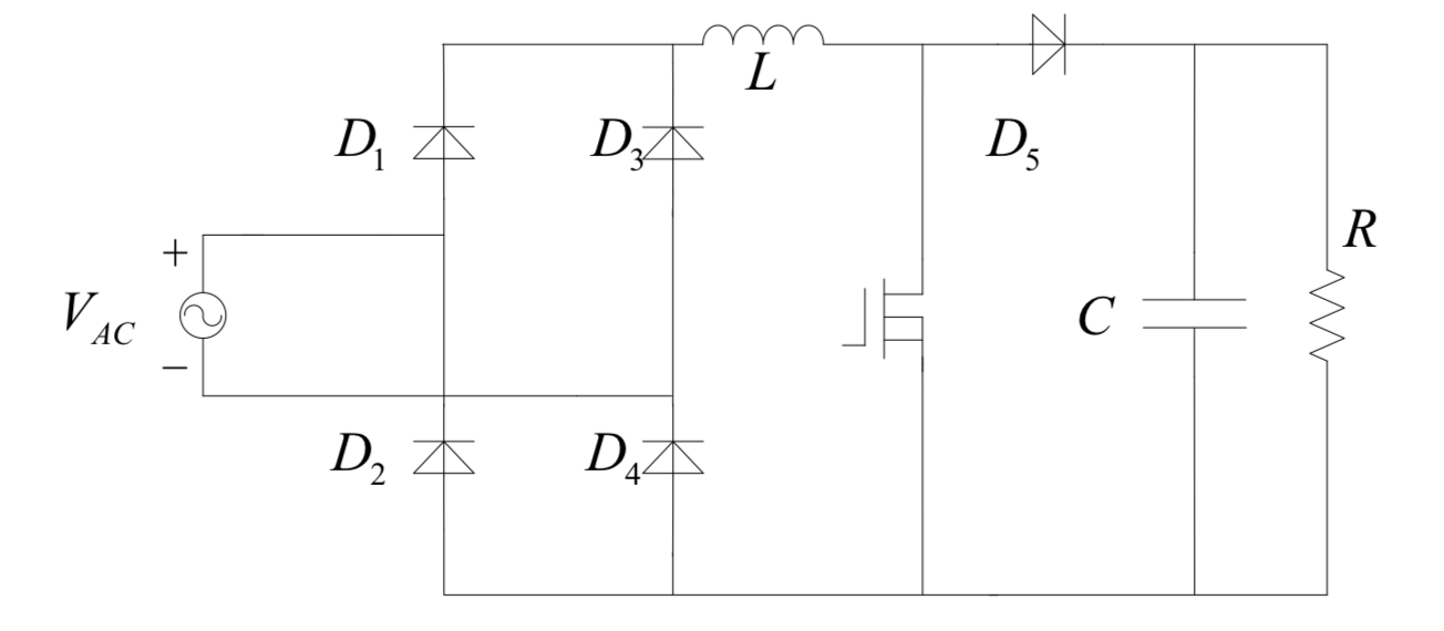
This is a typical APFC converter. The four diodes represent the bridge rectifier, which fully corrects the AC power stream after it passes the EMI/transient filter. During this process, AC is converted to higher-voltage DC (if we have 230V input, the bridge rectifier's DC output is √2x230=325.27VDC). Afterward, the DC signal is fed to the APFC stage's FETs.
The main disadvantages of this topology is its higher cost, since lots of components are needed and the control circuits are complex. Moreover, at the switching frequencies essential for high power output, the switching losses increase dramatically.
In a conventional APFC converter, voltage drops on two of the bridge diodes at a time, and droops at the boost stage. Obviously, those voltage drops limit the converter's efficiency, especially when the input voltage is low and the load is high. The only way to increase efficiency is to eliminate the bridge rectifier and use FETs instead of diodes, which don't have voltage drops.
A totem-pole bridgeless PFC converter looks to be the ideal solution, since two MOSFETs replace the bridge rectifier and two GaN MODFETs (HEMTs) are used as boost converters. The MODFETs' key feature is their much smaller reverse recovery charge (up to 20x), which minimizes energy losses.
Get Tom's Hardware's best news and in-depth reviews, straight to your inbox.
In a conventional APFC converter, when the conduction path is on, the signal has to pass through two low-speed diodes and one switch. When the conduction path is off, the signal passes from two low-speed diodes and a high-speed diode (SBR). In a totem-pole PFC, the signal passes through a MOSFET and a MODFET in both cases, so we theoretically have no voltage drops. This is why totem-pole PFCs achieve up to 99% efficiency, while the most efficient APFC circuits top out around 96%. If you want to read more about the totem-pole PFC converter, here are some interesting papers:
- Totem-Pole Bridgeless PFC Design Using MC56F82748
- Control challenges in a totem-pole PFC
- 99% Efficiency True-Bridgeless Totem-Pole PFC
The following video footage shows the Corsair AX1600i's internals.
MORE: Best Power Supplies
MORE: How We Test Power Supplies
MORE: All Power Supply Content
Current page: Teardown & Component Analysis
Prev Page Unboxing Video Next Page Load Regulation, Hold-Up Time & Inrush Current
Aris Mpitziopoulos is a contributing editor at Tom's Hardware, covering PSUs.
-
Quaddro all of we need is 500w class digital titanium++ psu with this advance technology..Reply
Well, pc is much more efficient right now..
I wonder how many people will use it anyway... -
Aris_Mp Videos working fine here.Reply
PCs are more efficient, however graphics cards once pushed are not and many users tend to overclock their GPUs. Moreover, those units are intended for multi-GPU systems. -
SoerenHedemand Do you do you fan and noise measurements with 110V or 220V? That should make a difference in this case at least.Reply -
Aris_Mp Reply20574970 said:Do you do you fan and noise measurements with 110V or 220V? That should make a difference in this case at least.
115V but I also take noise measurements with 230V because of Cybenetics.
115V: 23.25 dB(A)
230V: 23.29 dB(A)
-
SoerenHedemand Specifically at what point does it change from passive to active cooling using either 110V or 220V?Reply -
ptlin.ece90g Primary DSC should be NXP Freescale MC56F8236Reply
Secondary DSC is Texas Instruments UCD3138064A

