How To Build A $1,000 Gaming PC
The $1,000 Best PC Build is proof positive that you can outfit a platform with an Intel Core i5 processor, a GeForce GTX 1070 graphics card, 16GB of RAM, and a modular 80 PLUS Gold-certified PSU for a moderate price.
The locked CPU saves money on the build with its included heatsink, but the performance ceiling is noticeably lower than the potent and unlocked Core i5-7600K we’ve seen in other builds. The graphics card is definitely powerful for the total cost of the build (it’s almost 40% of the total budget), and that GPU is the cornerstone of this rig.
The ASRock B250M Pro 4 is a sturdy platform with which to build a non-overclocked gaming rig, with a feature set that allows for upgrades down the line (although some features, such as the two Ultra M.2 slots, go to waste with this particular build). The memory is a perfect fit, matching the CPU’s stock memory controller speed. 16GB is also more than adequate for any AAA game title currently available.
However, that’s not to say that Provost’s Pick doesn’t fall flat with a few of its components. The case is decidedly plain and uncooperative, with a flimsy feel and weight that doesn’t portend gaming greatness underneath the hood. At least it has USB 3.0 front ports. However, Damric was well aware of its shortcomings (it's better than a shoe box) when he selected it, but a few concessions had to be made in order to have enough budget for a GTX 1070.
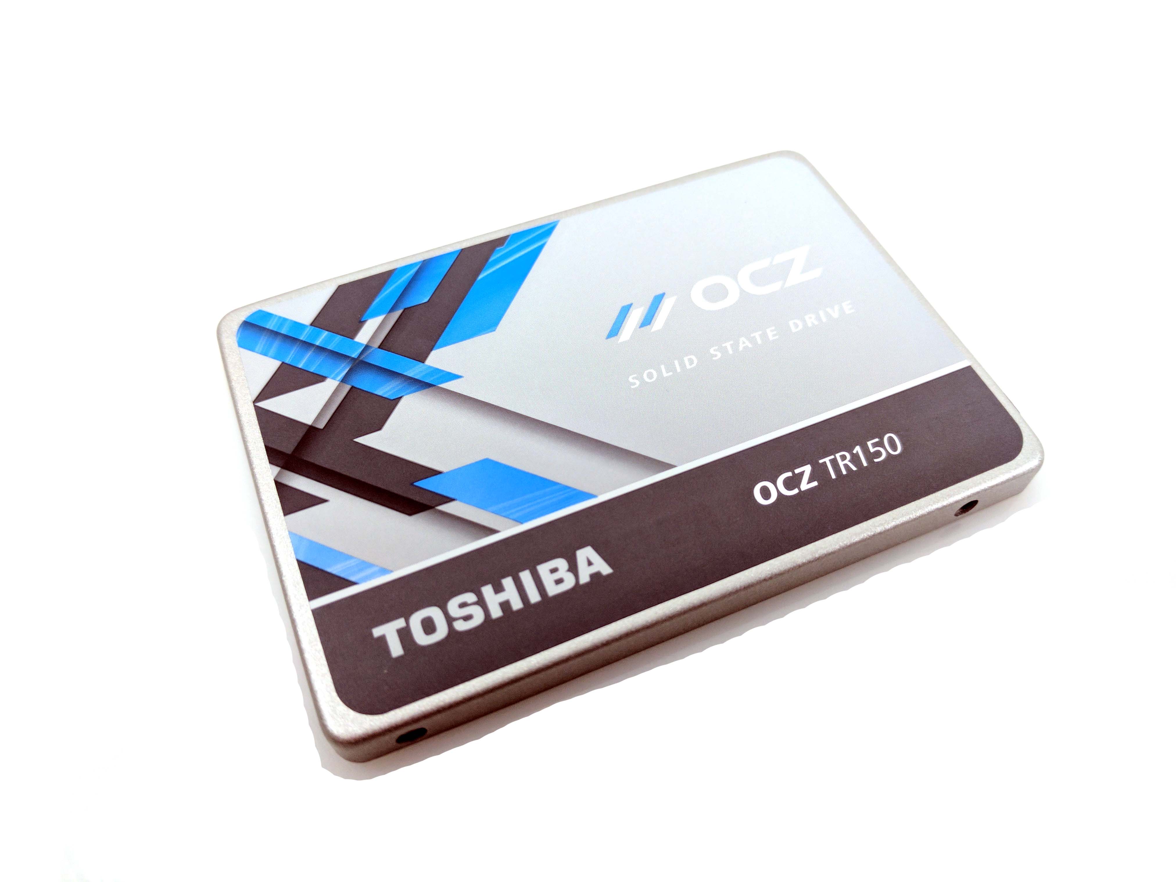
The 480GB SSD is definitely better than a traditional HDD, but the OCZ Trion 150 is sandbagged with TLC flash, which is generally less durable than slightly pricier MLC SSDs. However, the capacity and speed would be difficult to match at this price, and we’re thankful for the flash storage over a slower (sometimes painfully) HDD.
Despite those few shortcomings, you would be hard pressed to get a system with these specs for anything less than this price, and we applaud the sheer tenacity of going for big gaming performance without breaking the bank.
Specifications
| "Provost's Pick" by Damric | |
|---|---|
| Case | T2 Plus |
| CPU | Core i5-7500 |
| Graphics | Zotac GTX 1070 |
| Memory | Mushkin Enhanced Backline 16GB (2 x 8GB) DDR4 RAM |
| Motherboard | B250M Pro4 |
| Power Supply | CX550M |
| Storage | Toshiba OCZ Trion 150 480GB TRN150-25SAT3-480G |
Now let's assemble the Best $1000 PC Build.
Get Tom's Hardware's best news and in-depth reviews, straight to your inbox.
The Case
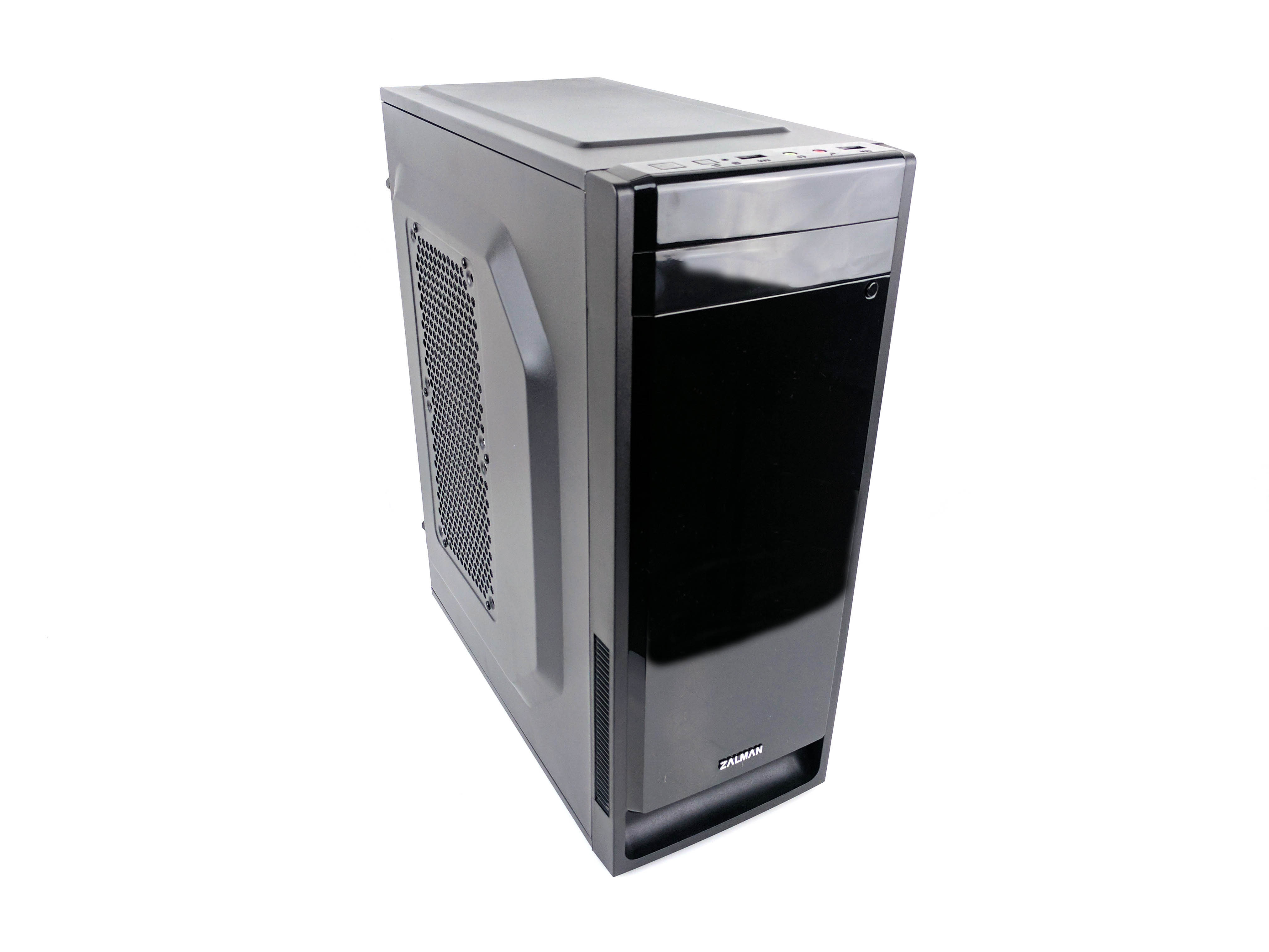
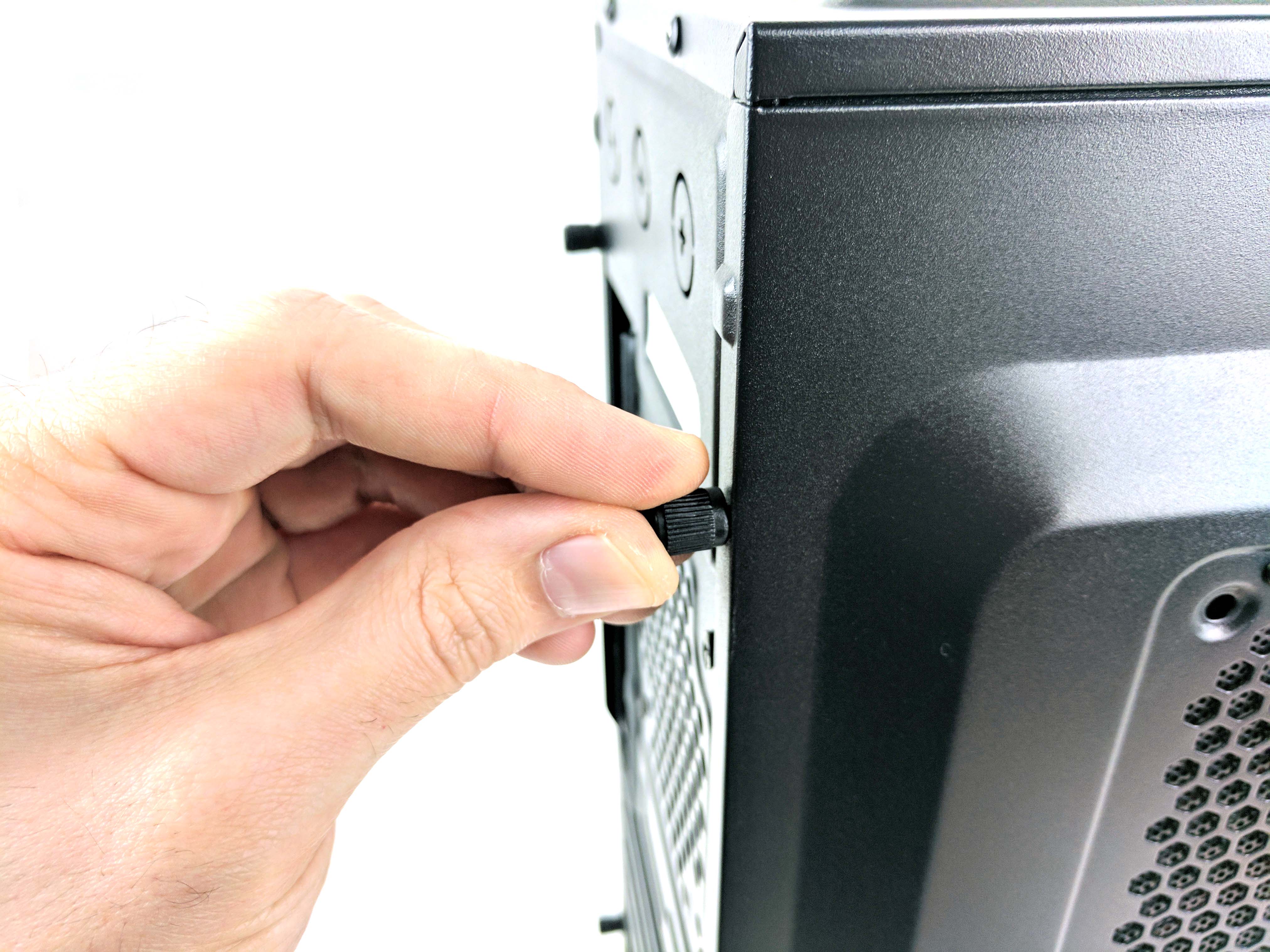
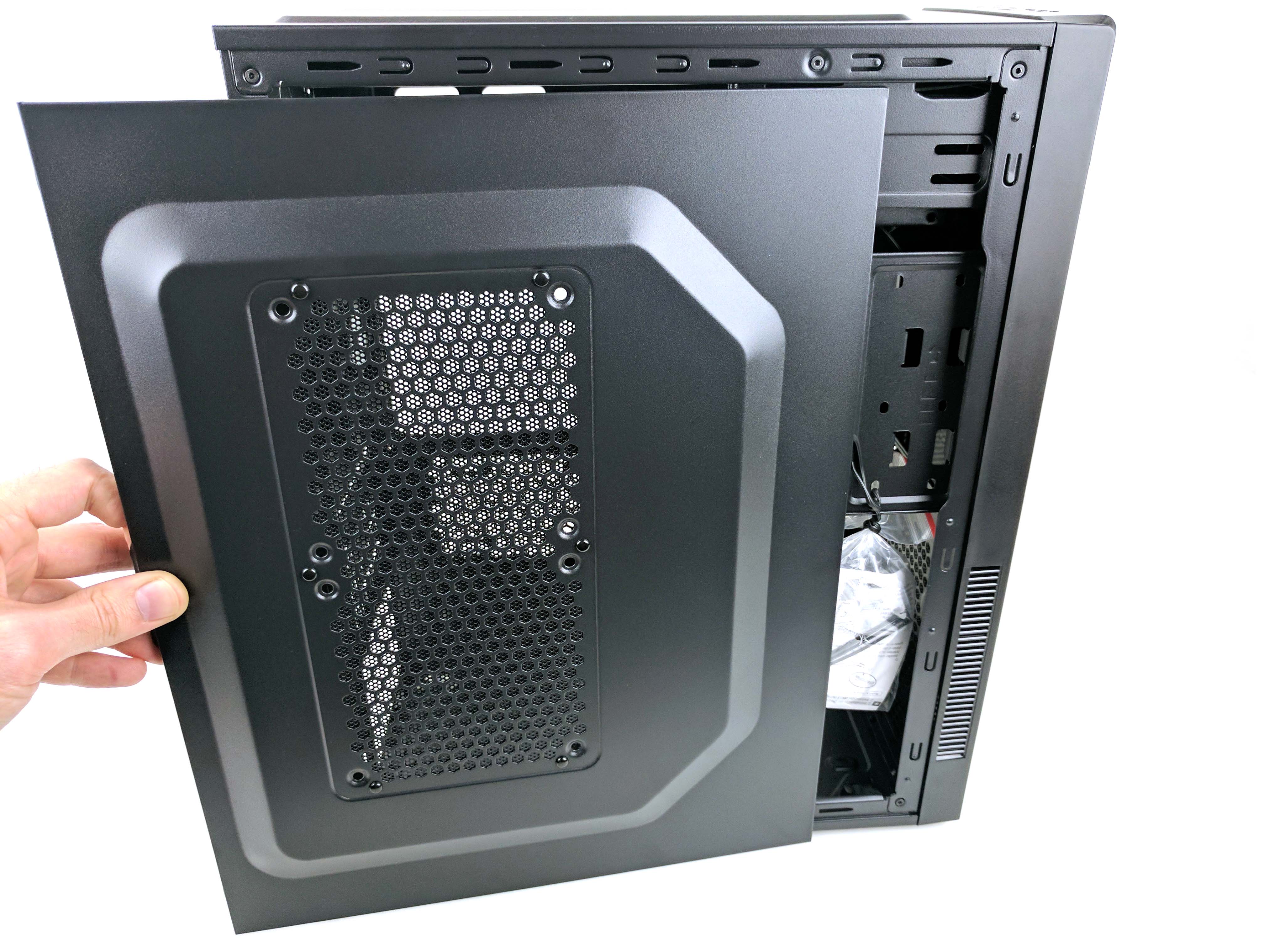
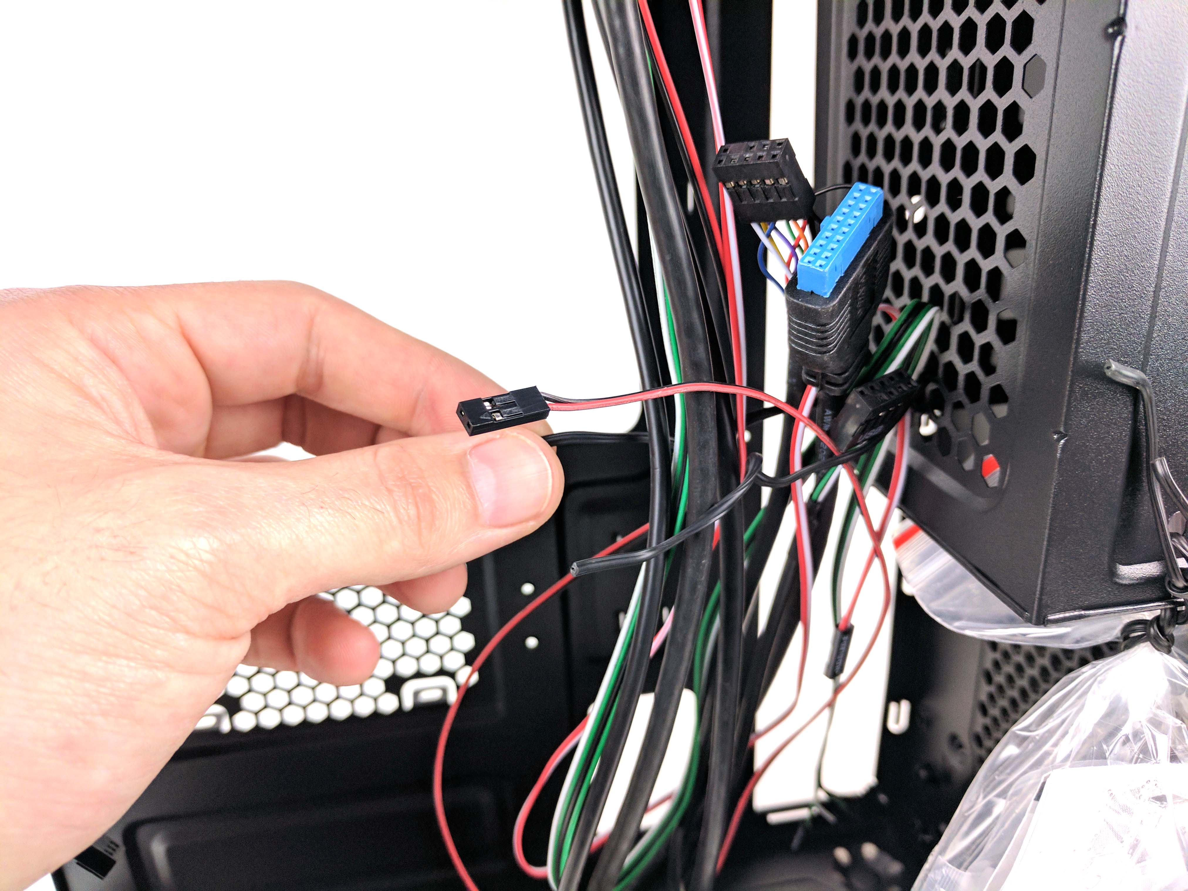
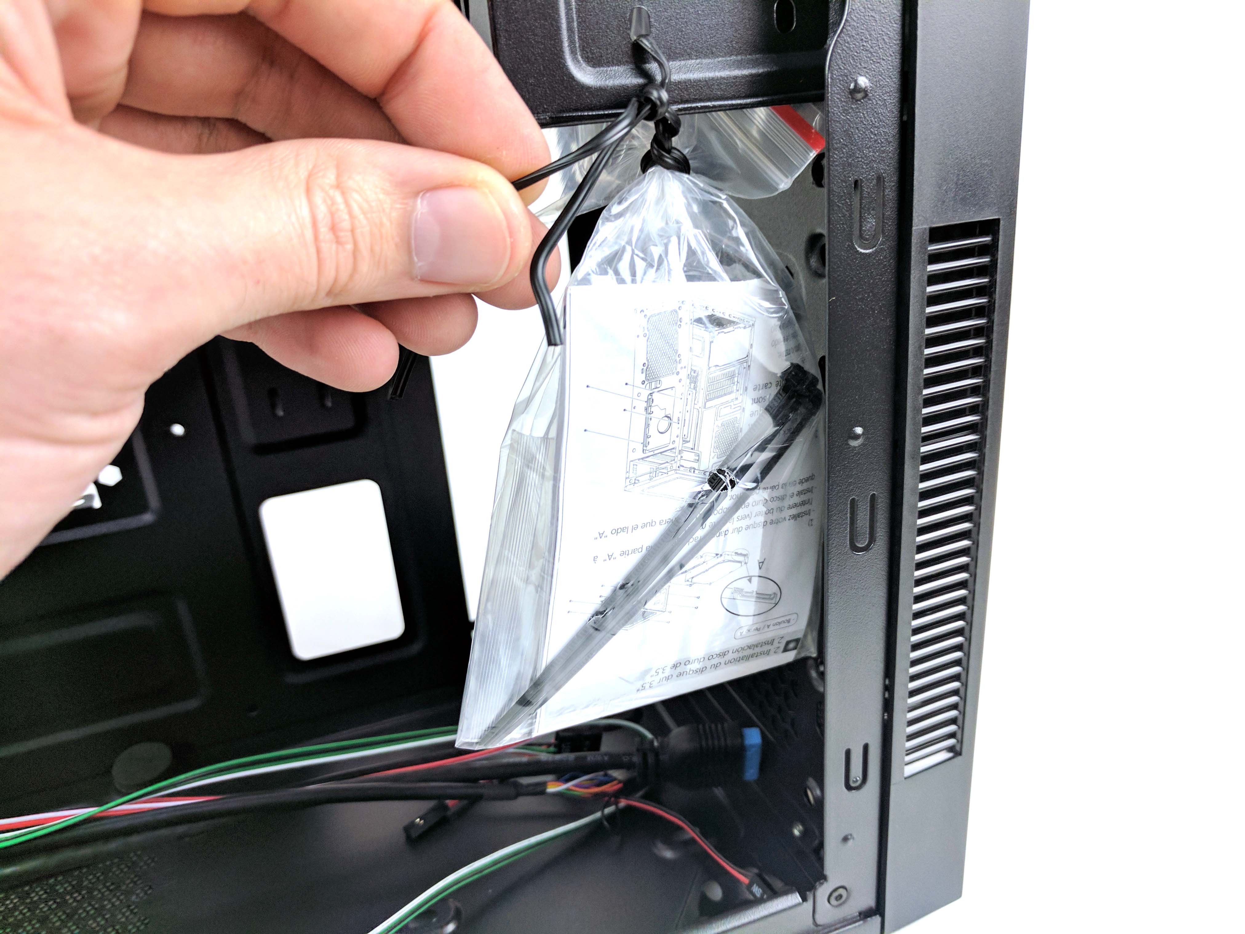
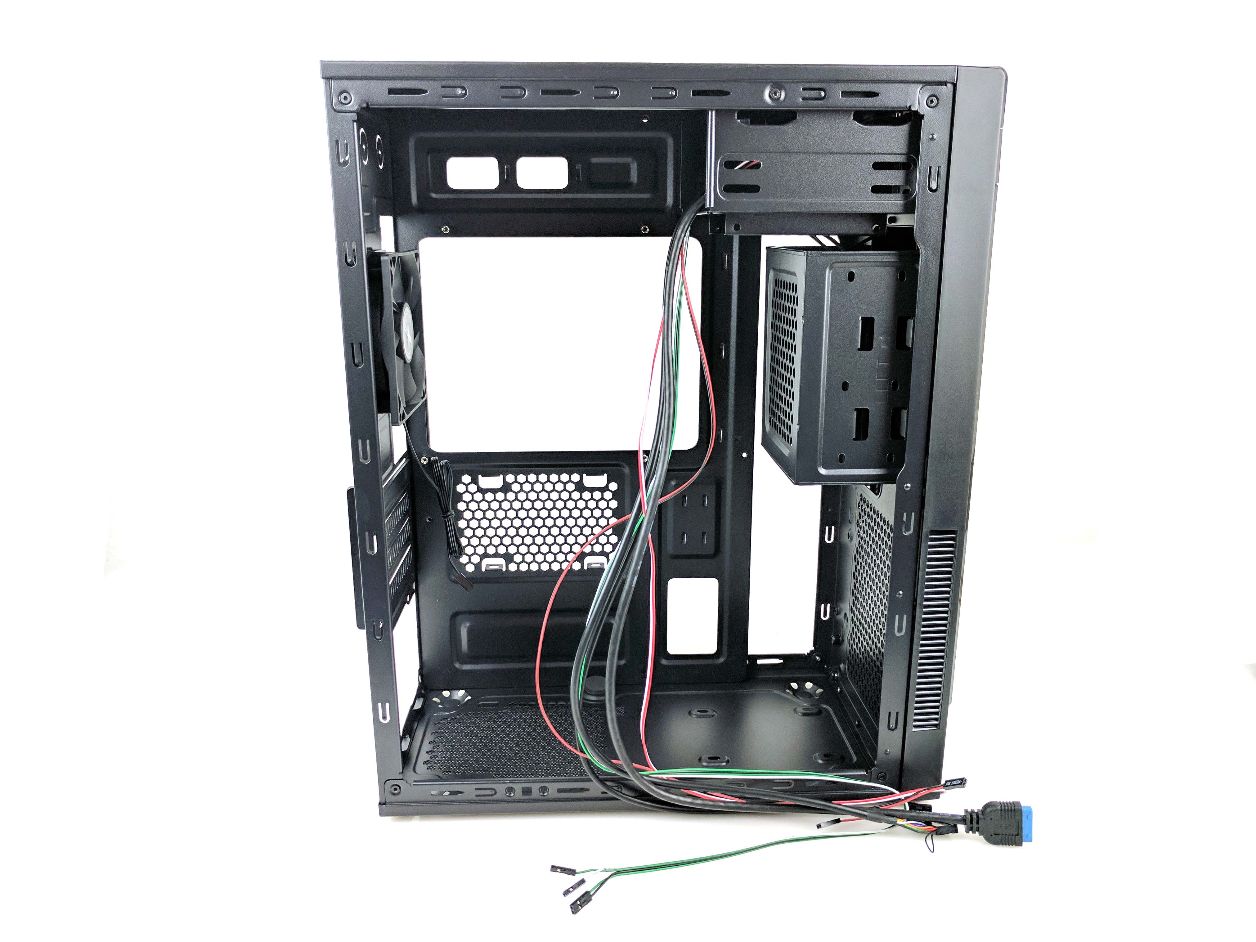
Remove the Zalman T2 Plus micro-ATX case from its box and unscrew the thumbscrews holding the panels in place (slide 2 in the album below). They aren’t particularly tight, so you should be able to use your hands. Detach the side panels and set them aside. Take out the hardware and silica bags by untwisting the tie wraps holding them to the case. Free the internal cables (front I/O, USB 2.0, USB 3.0, audio) in the same fashion (slides 5 - 7).
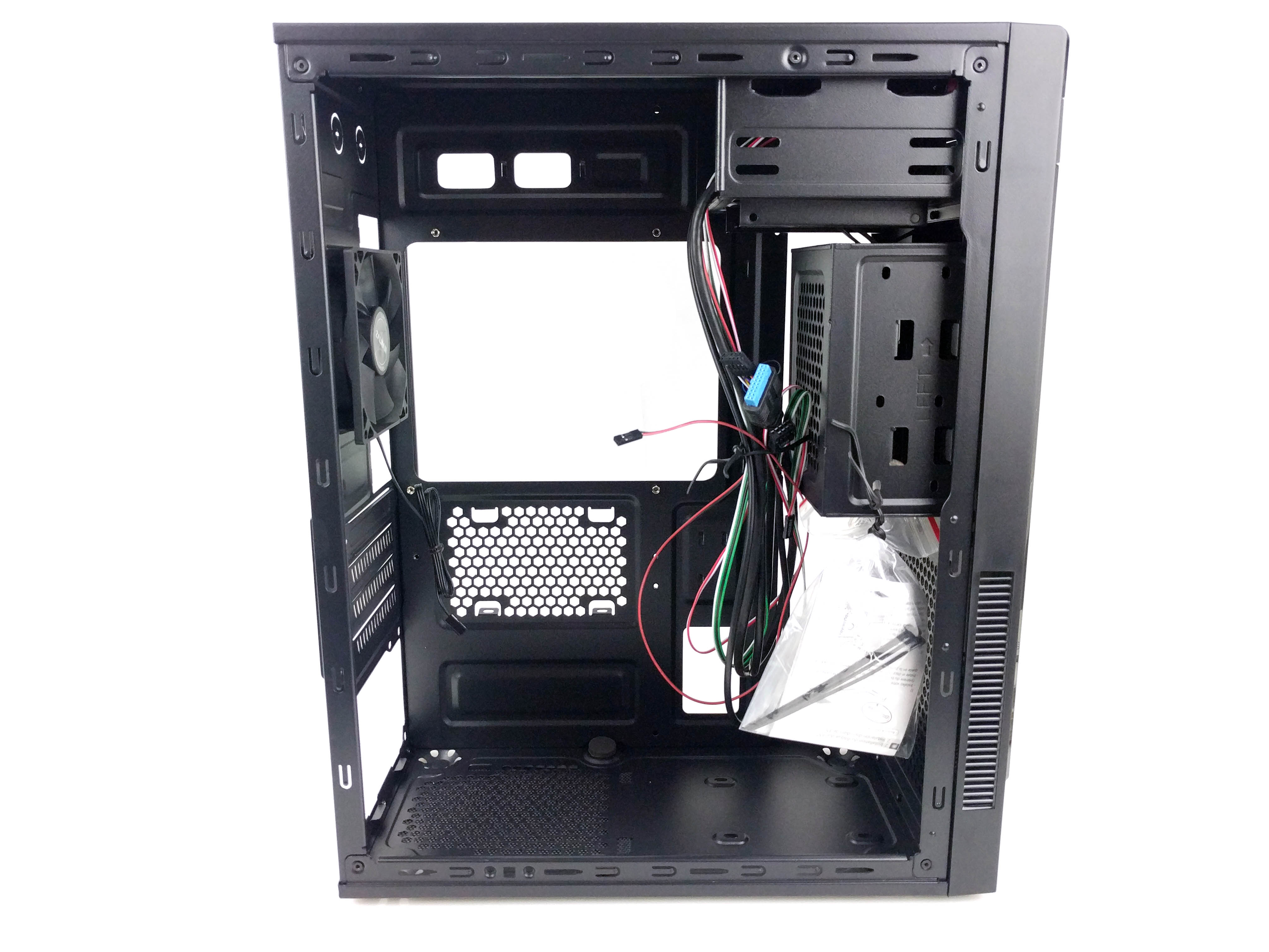
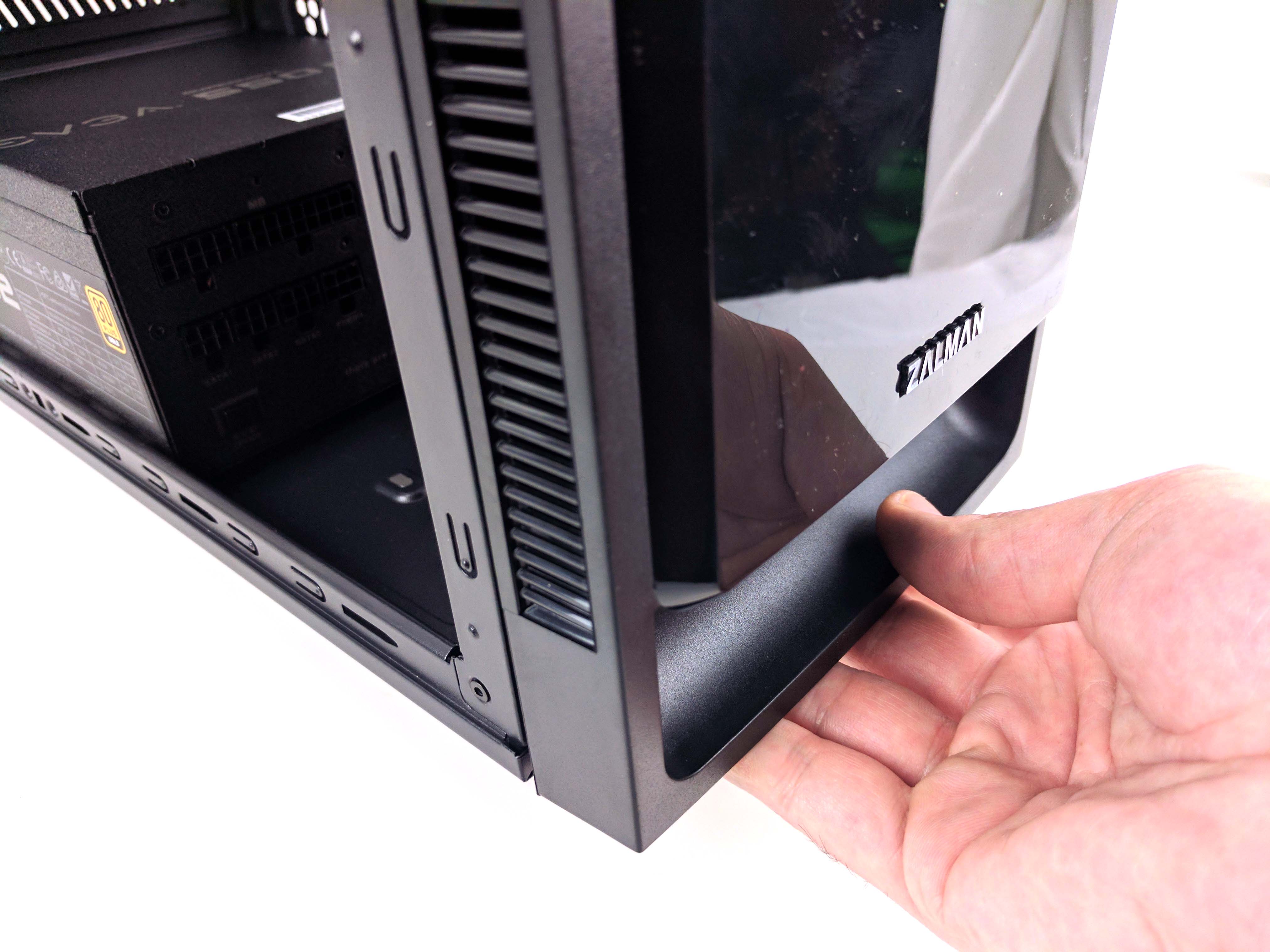
In order to properly attach all of the motherboard standoffs to the chassis, you’ll have to remove the 3.5” drive bay at the front of the case. Begin by tugging on the bottom lip of the case’s front panel until it comes free (see the first picture in the album below). A swift, quick motion works best. You can leave the panel somewhat ajar of the main chassis without fully removing it (and its front panel I/O wiring). You just need to get to the four screws holding the bay in place, which can be accomplished by pivoting the panel left and right (you can see this in pictures 2 and 3 below).
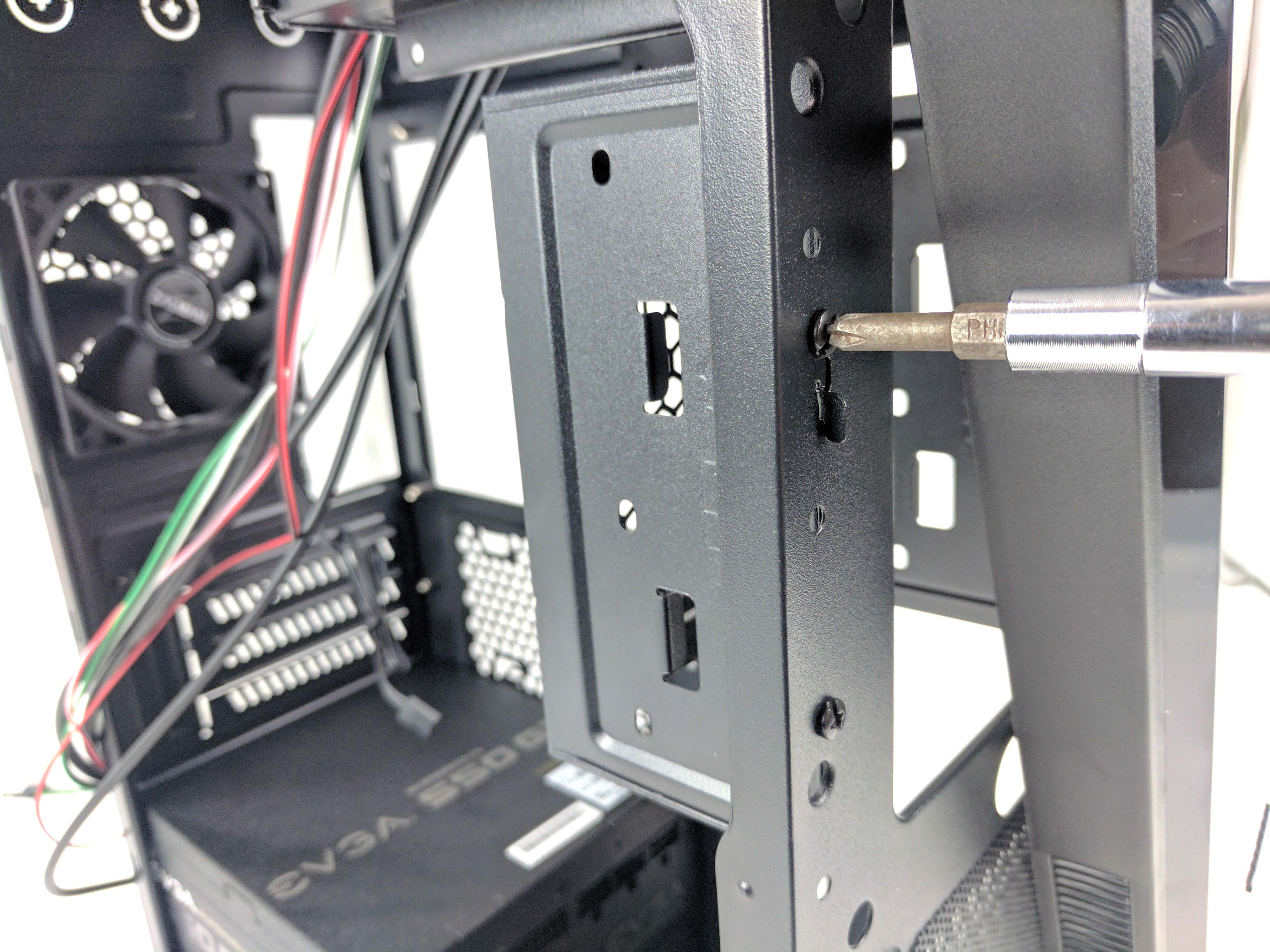
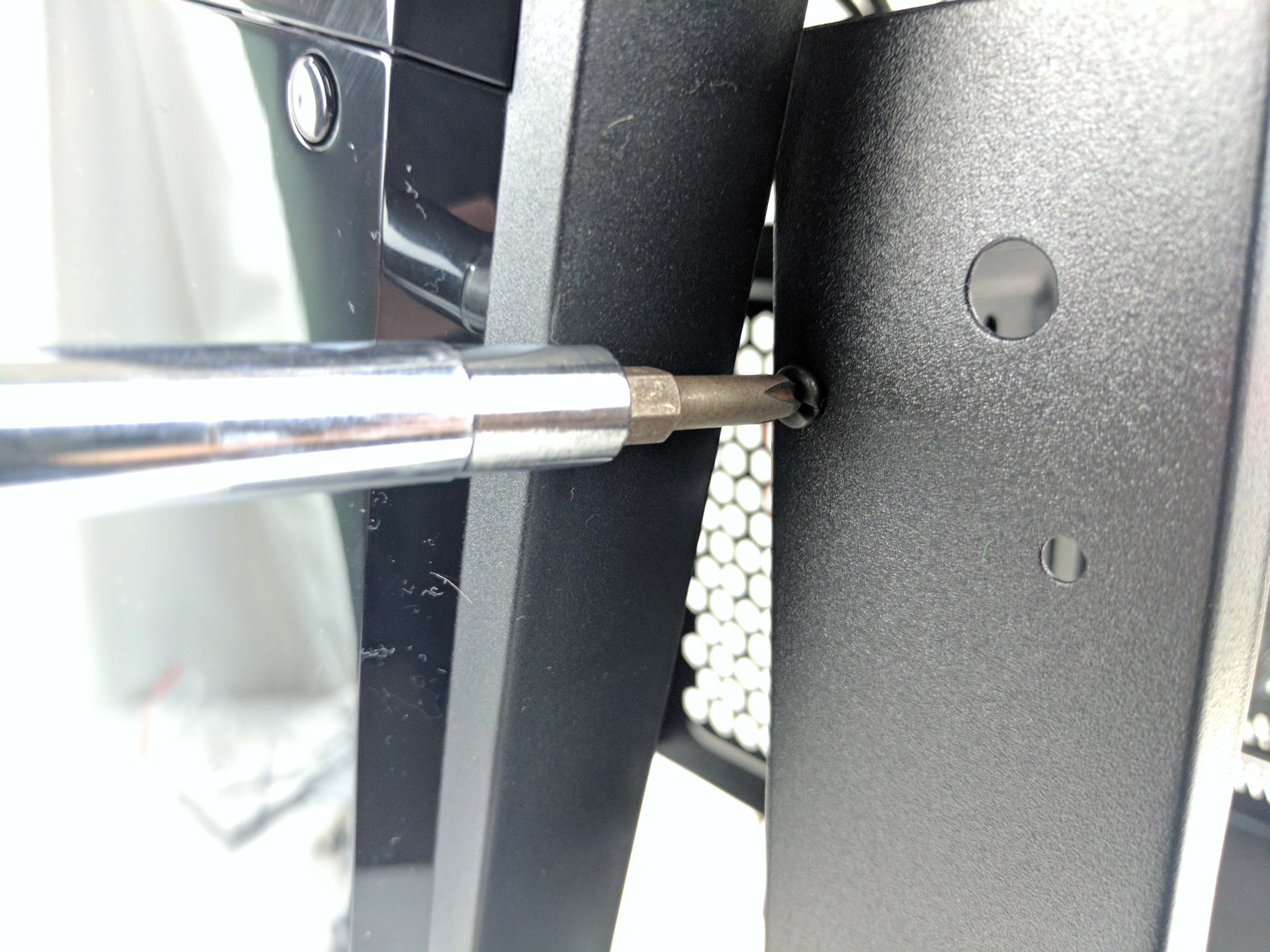
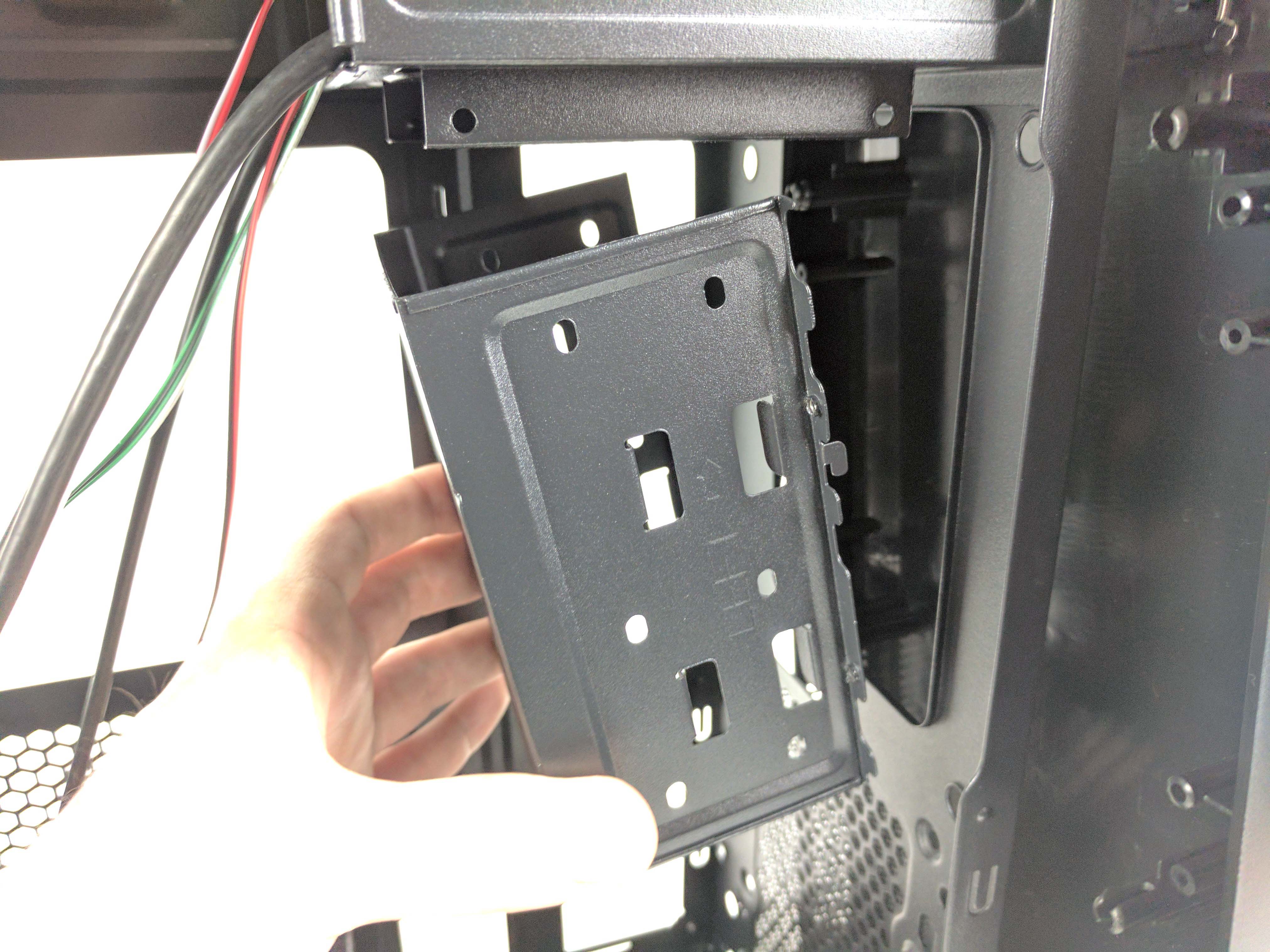
Remove the four screws beneath the 3.5” drive bay. Grab the bay from either side and slide it upwards to release it from the chassis (4th picture above). At this point, we’d recommend finding a permanent home for the bay and its screws in a closet somewhere; we won’t need it for this particular build. If you decide to add some hardware to the machine later on, it could come in handy, but even then you’d have to wait until after you install the motherboard to replace the cage. Refasten the front panel to the chassis and pull the case wiring away from the internal chassis.
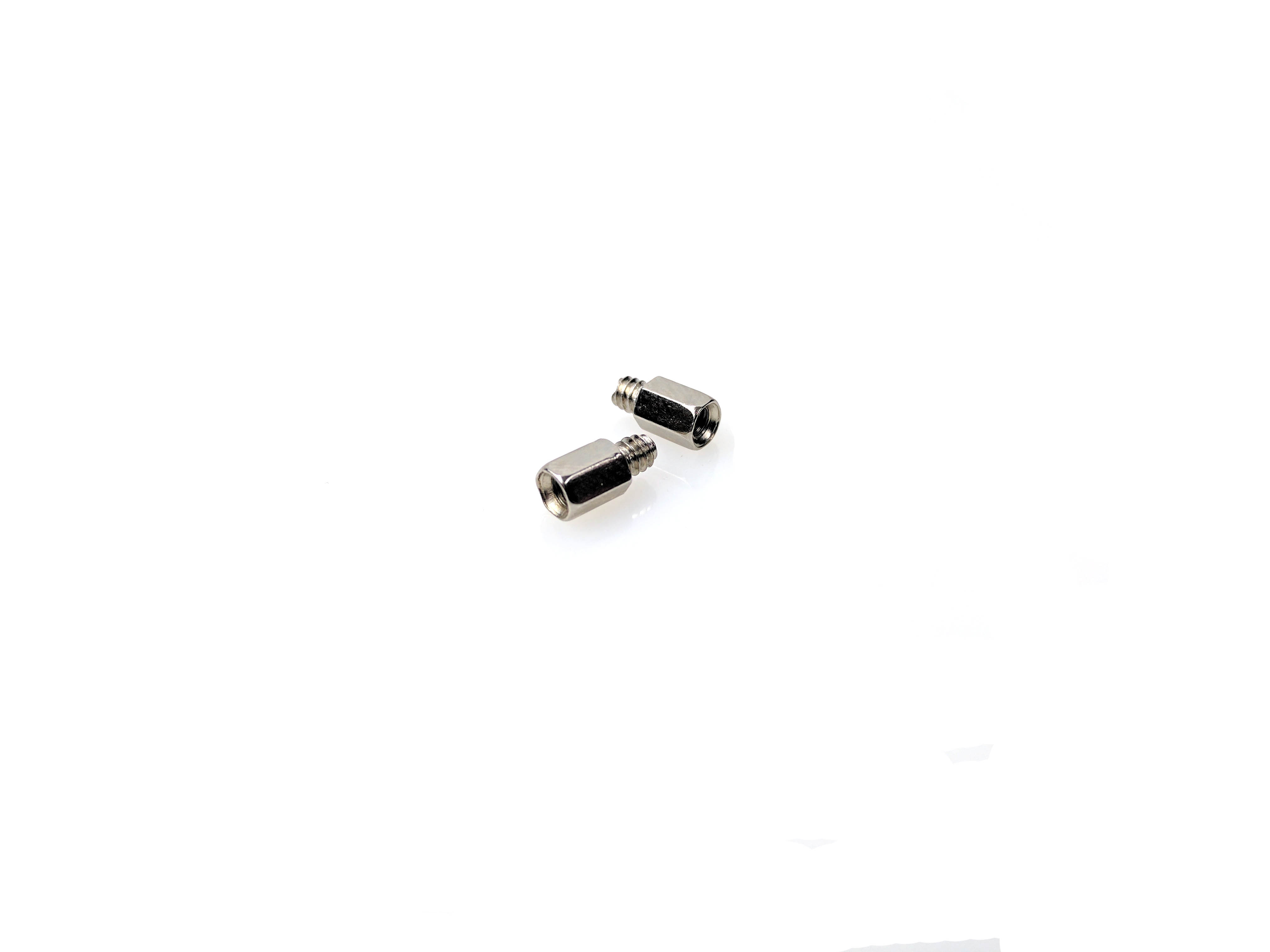
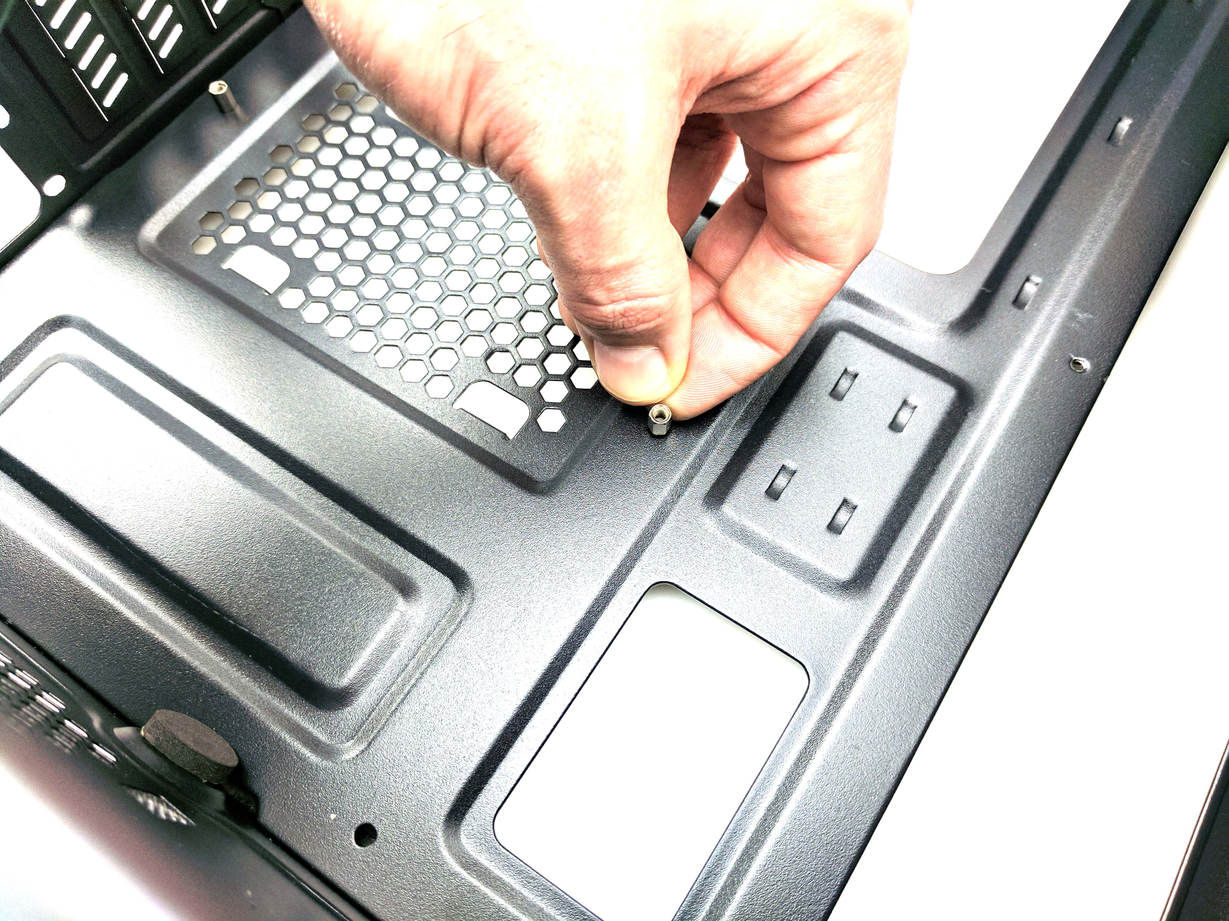
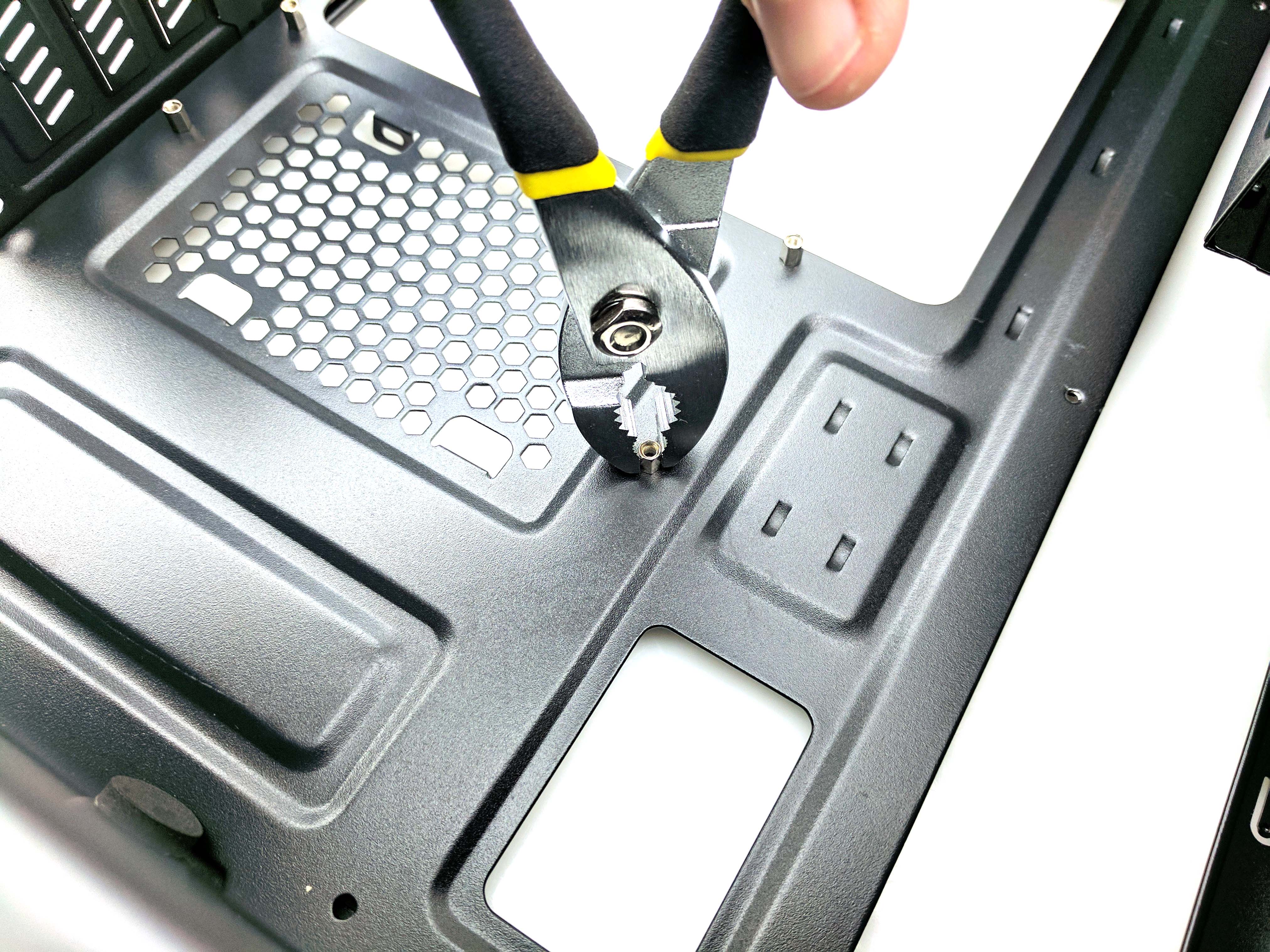
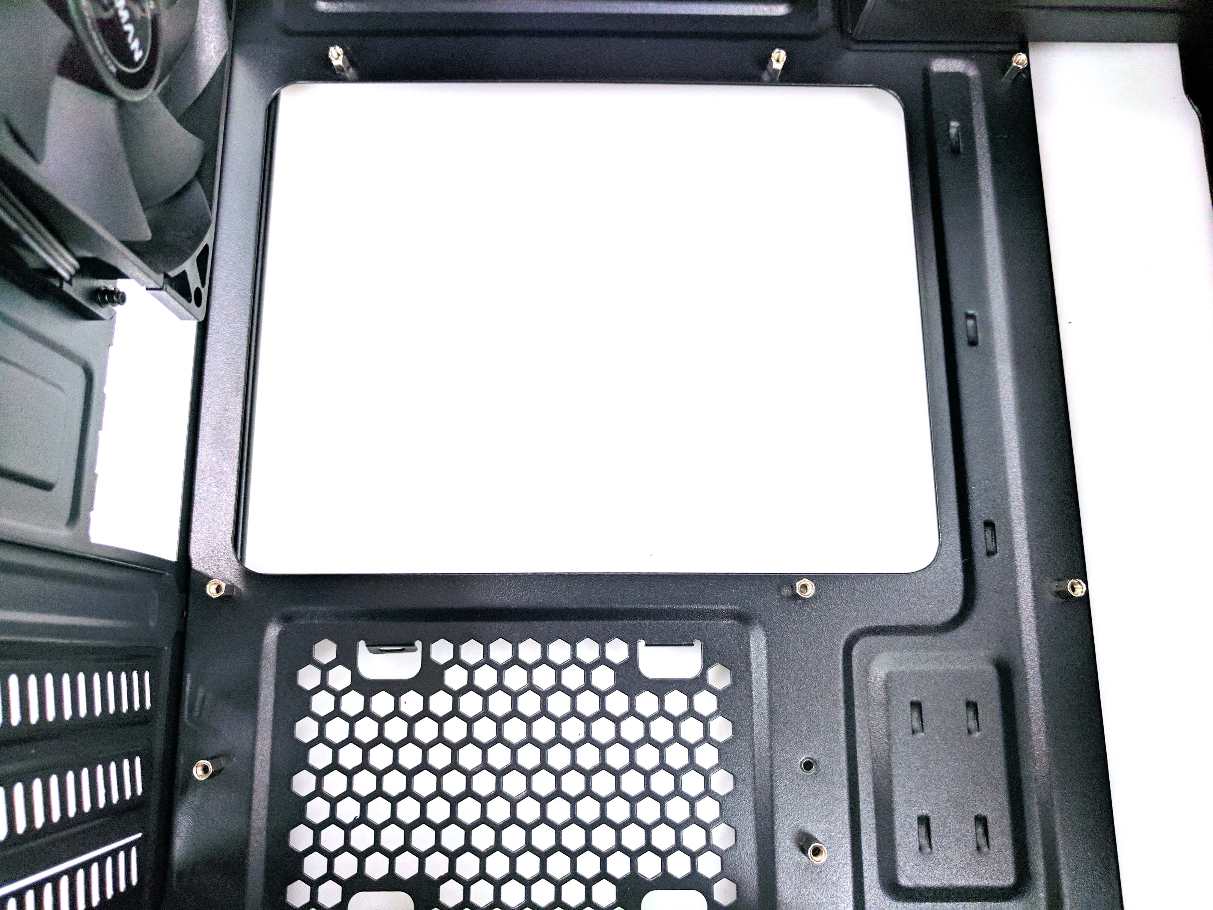
Now that you have a clear avenue in which to work, locate and attach the motherboard standoffs to the appropriate spots in the case (there are no labels, so check out the last photo in the album above, or eye it up with your motherboard). Tighten the posts with your fingers at first. Use a pair of pliers to make them snug after they are mostly tight (there isn’t an included tool, unfortunately).
The Power Supply
Remove the EVGA Supernova G2 550W power supply from its box. It’s fully modular, so you don’t have to worry about any of the cables yet. Line up the PSU and set it on the cushions and above the ledges near the back panel (see picture 2 in the album below).
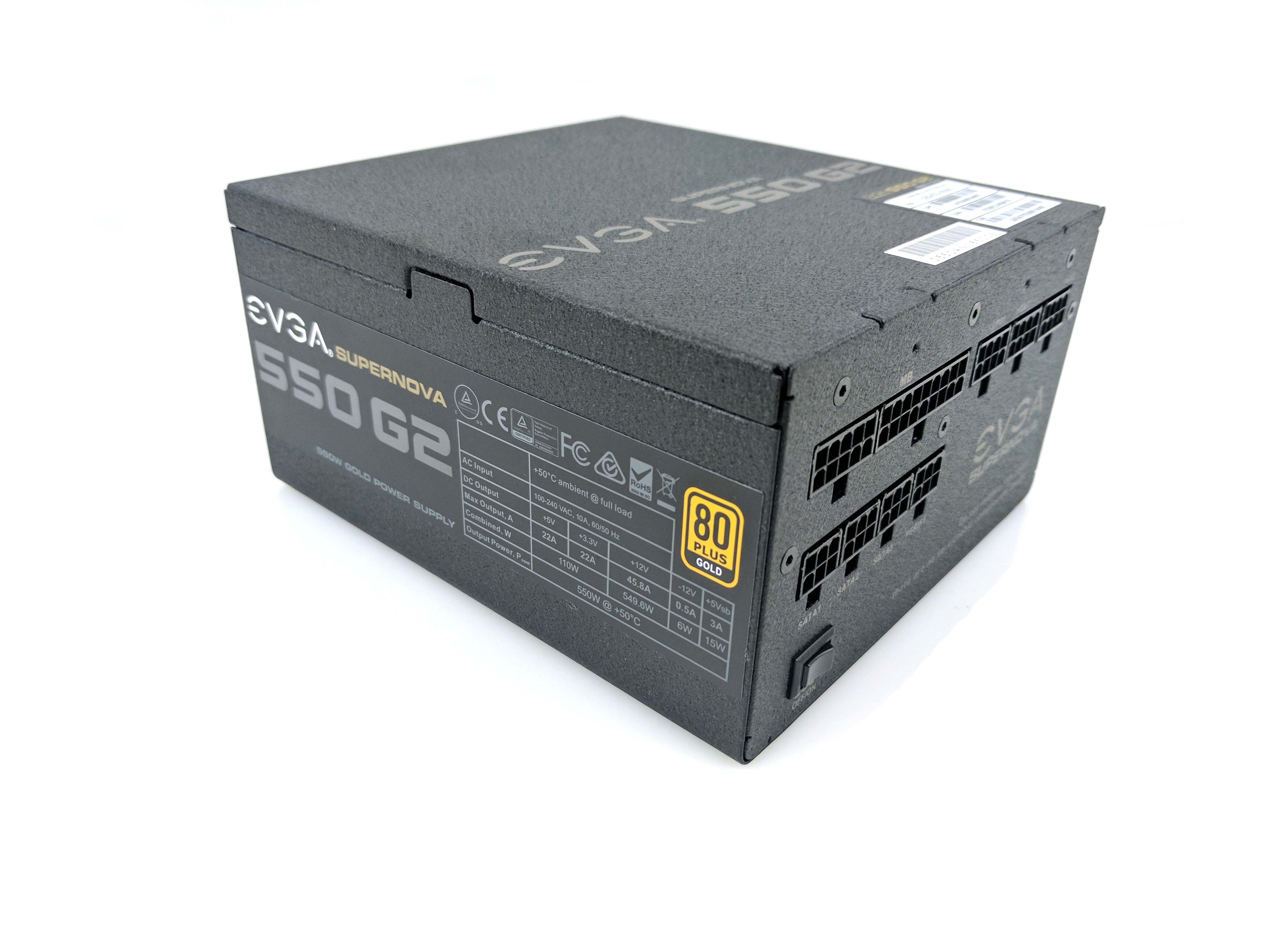
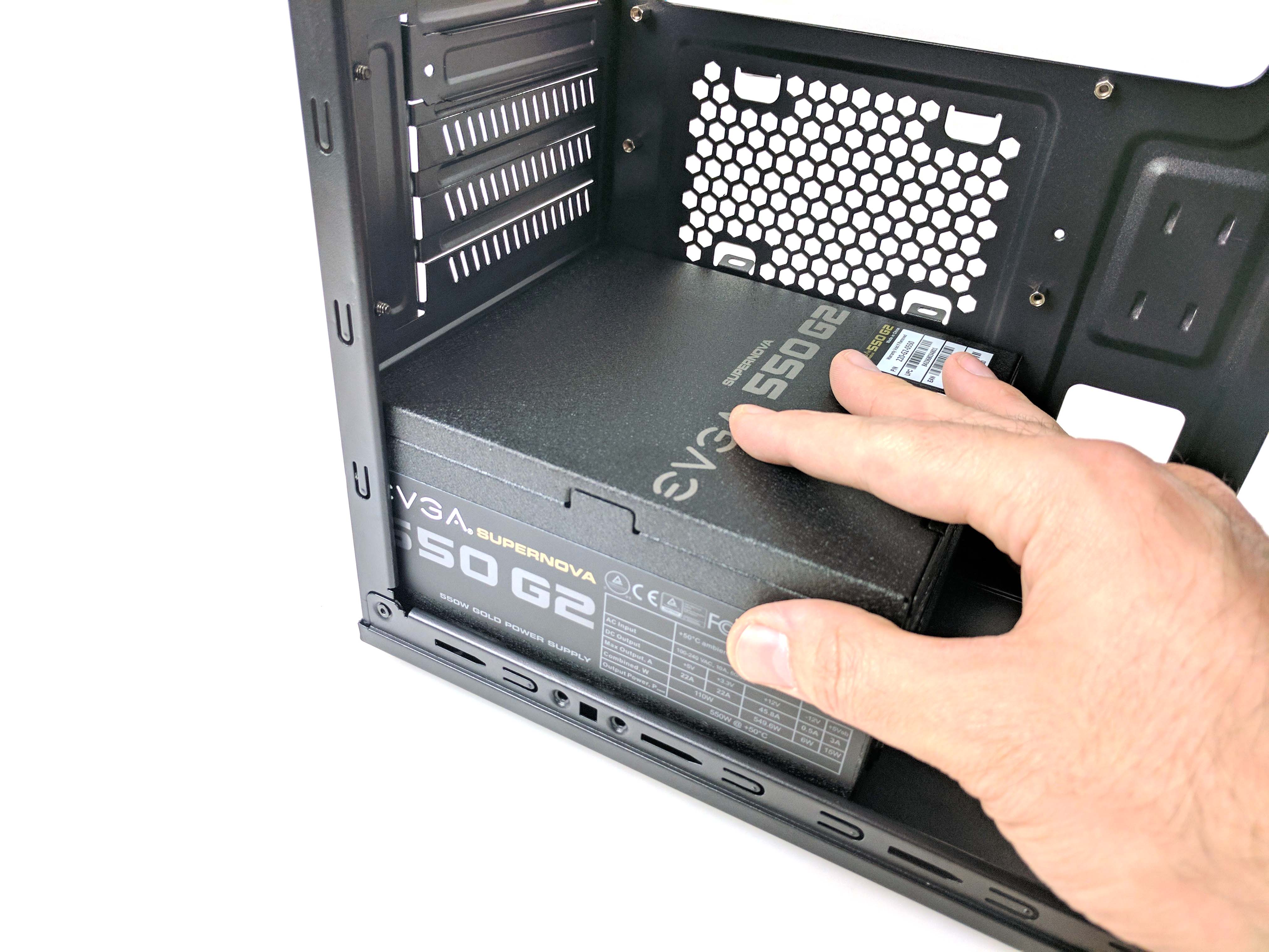
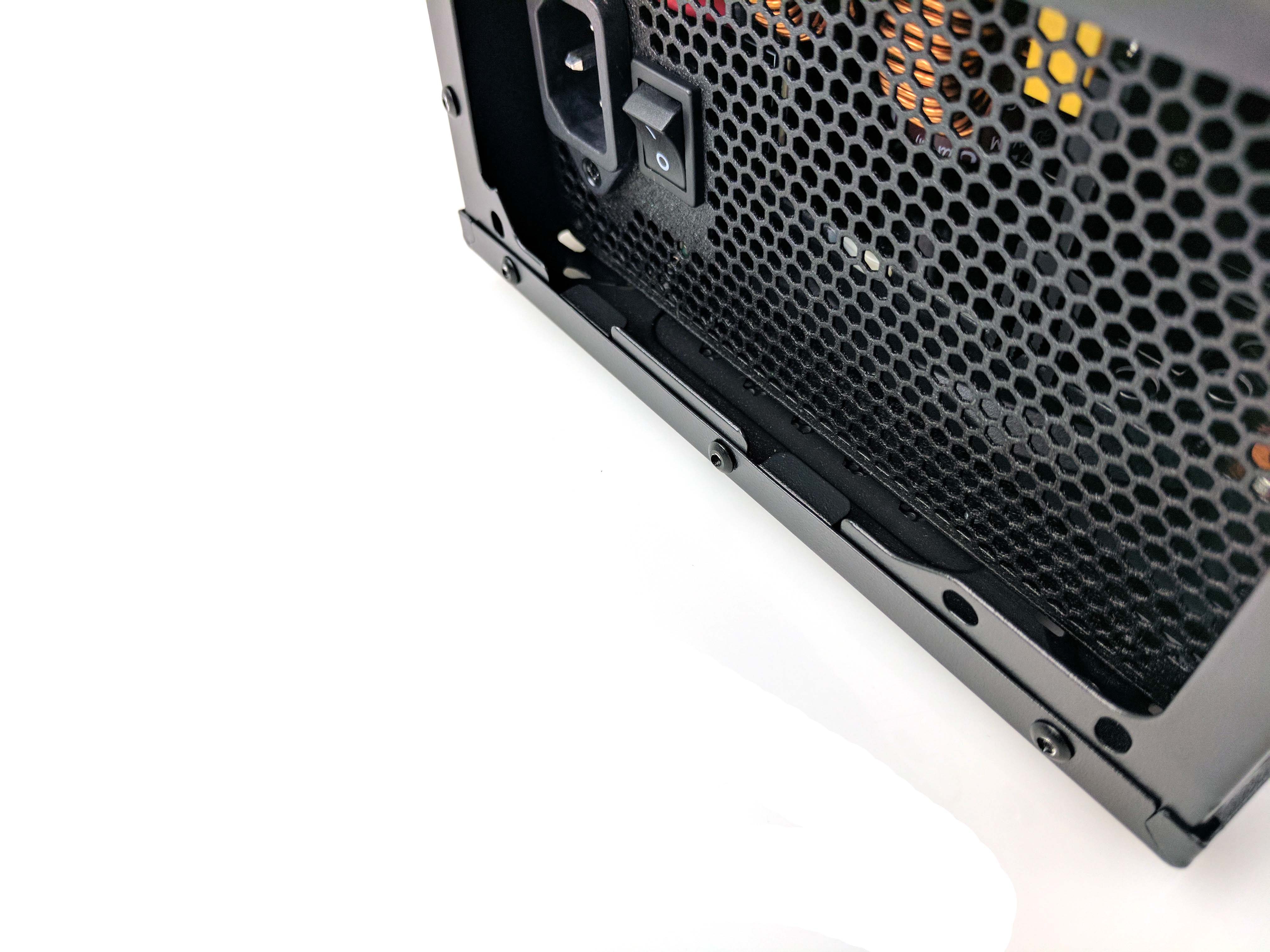
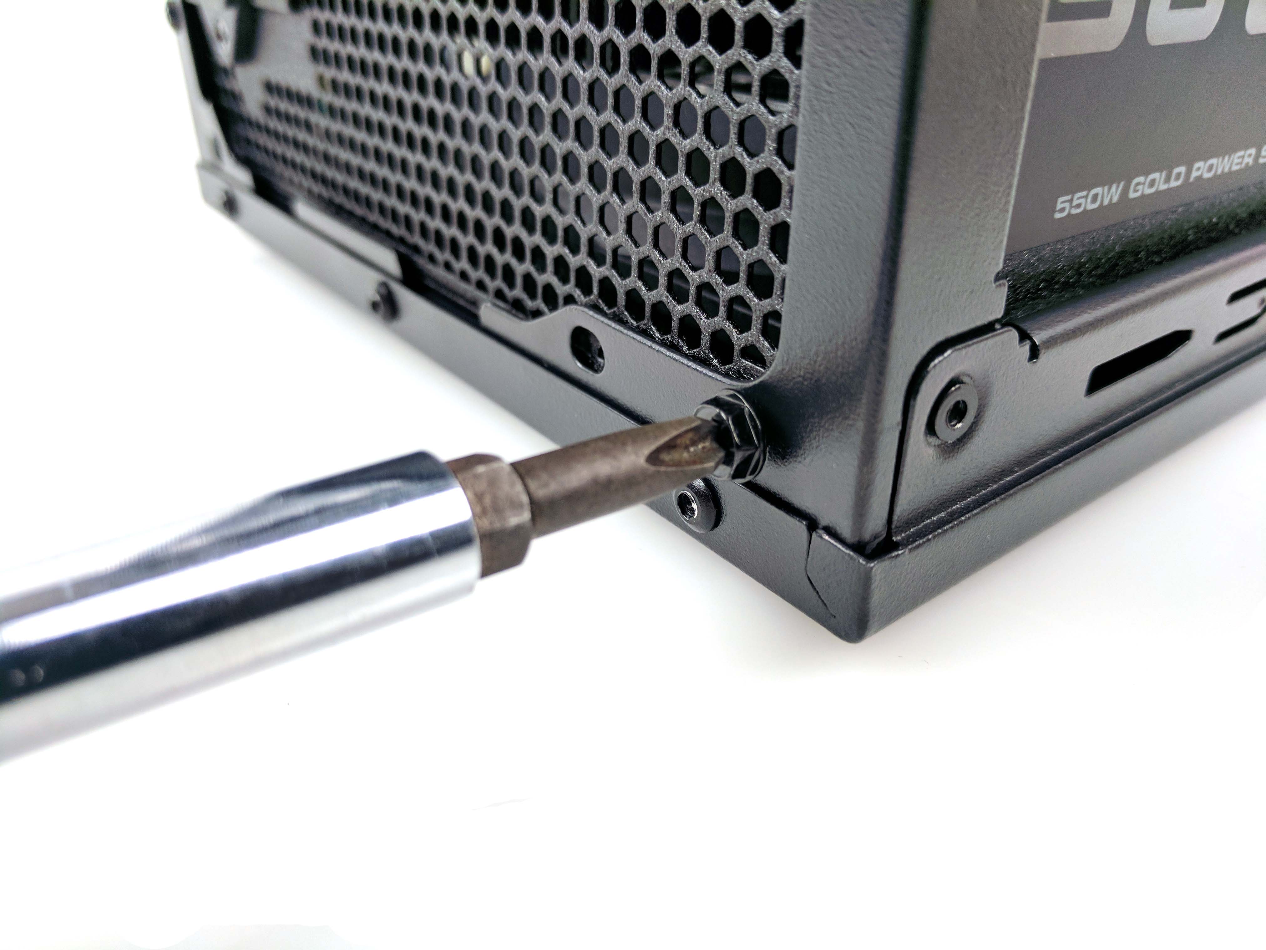
We found it quite difficult to get the PSU to fit properly in this particular case. The ledges were angled upward (lifting the power supply), so we had to apply some considerable pressure downward to bend the ledges enough to line up the screw holes. You may want to start with the bottom right screw when you attach the PSU to the case; we found that the easiest to get started, and the rest fell into place after tightening the first one. After you secure all four of the provided screws, set the case aside and get ready to prepare the motherboard.
The CPU & Motherboard
Remove the ASRock B250M Pro4 motherboard from its box, along with its rear I/O backplate and SATA data cables (set both aside for now). The board comes with a foam padding, which is a perfect place to rest it as you attach the next few components.
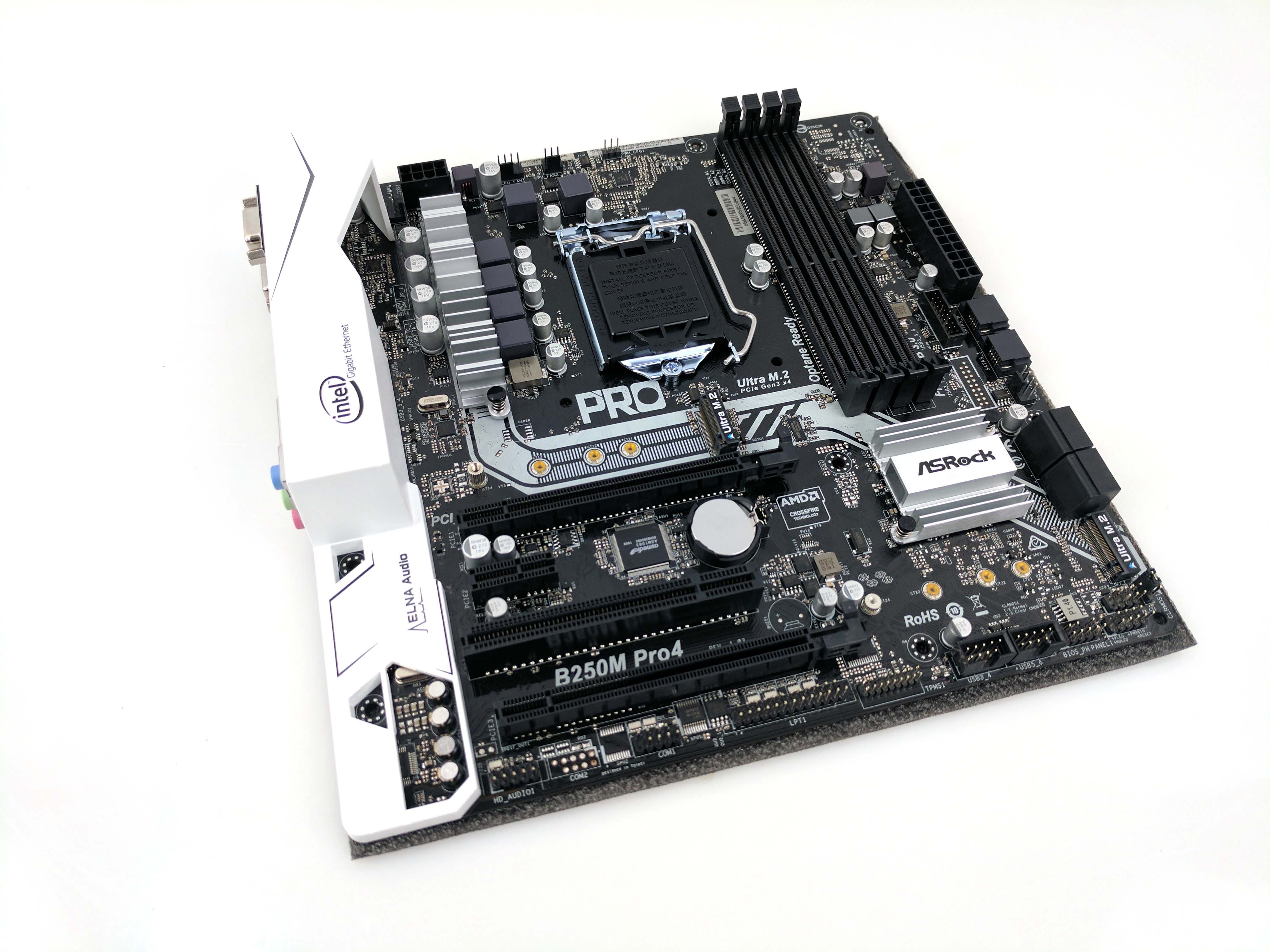
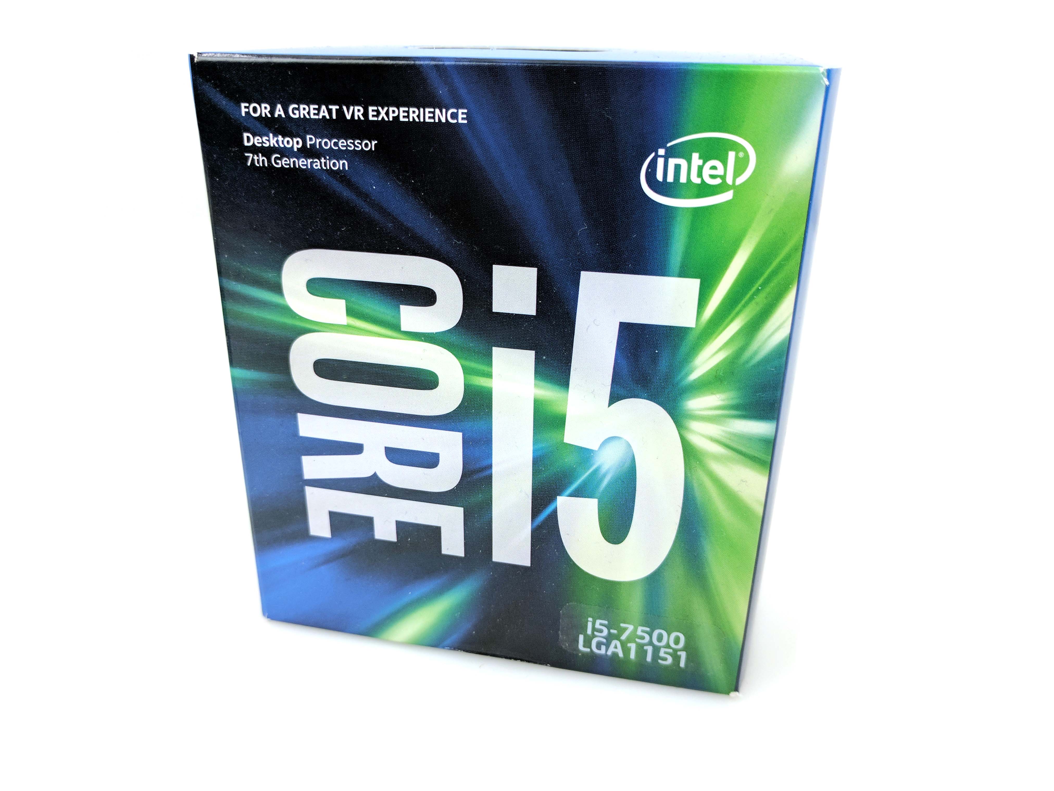
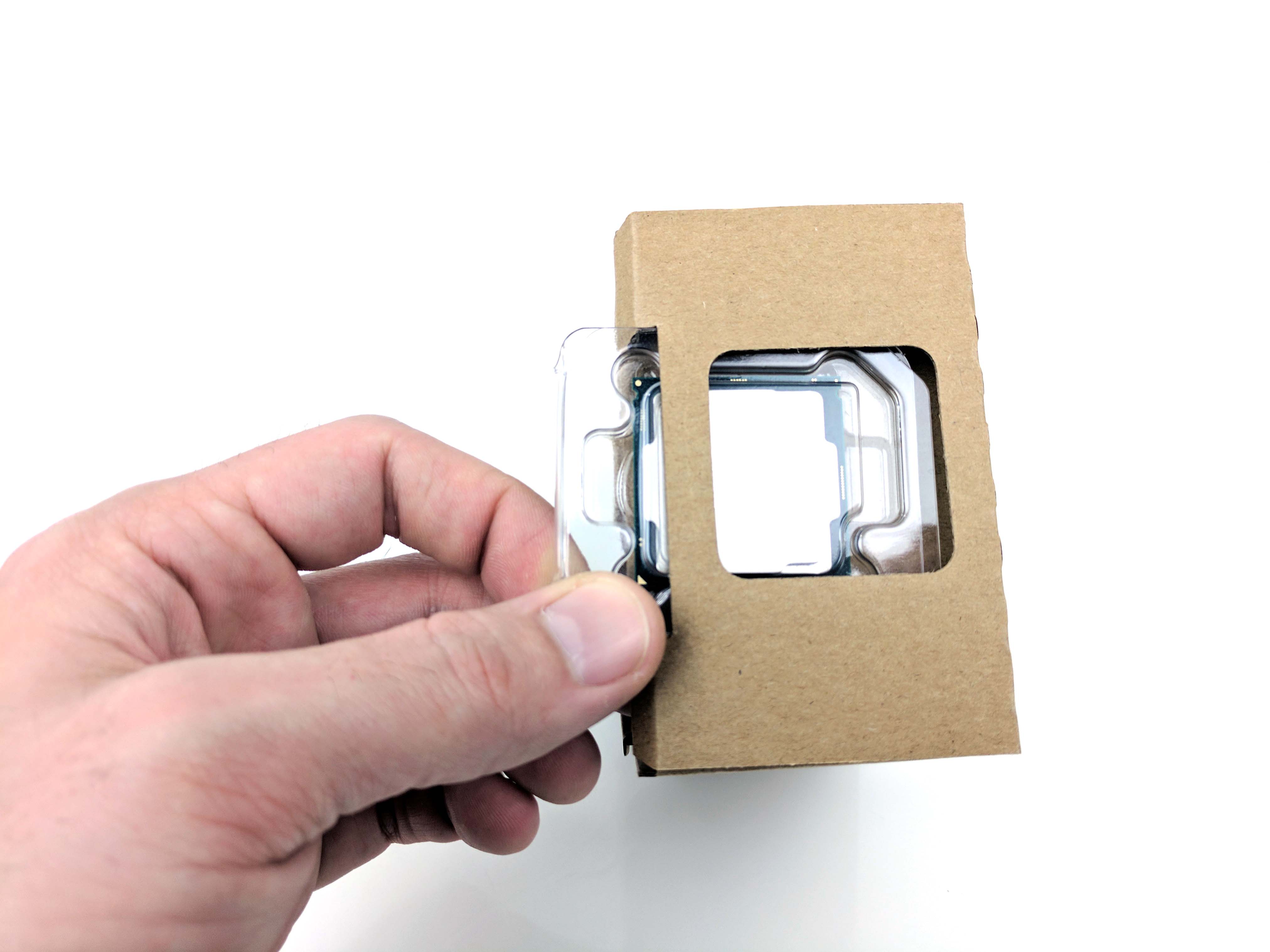
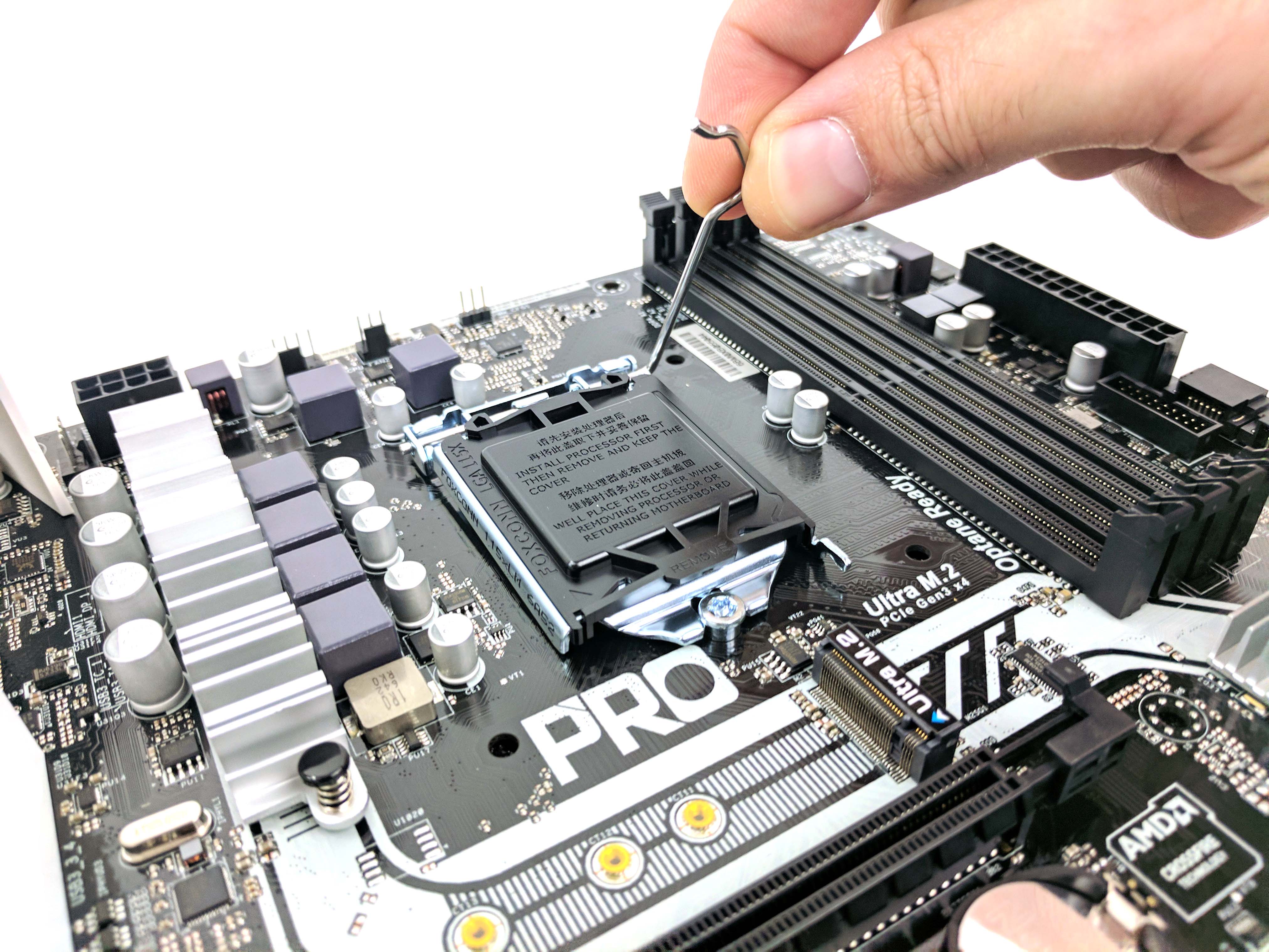
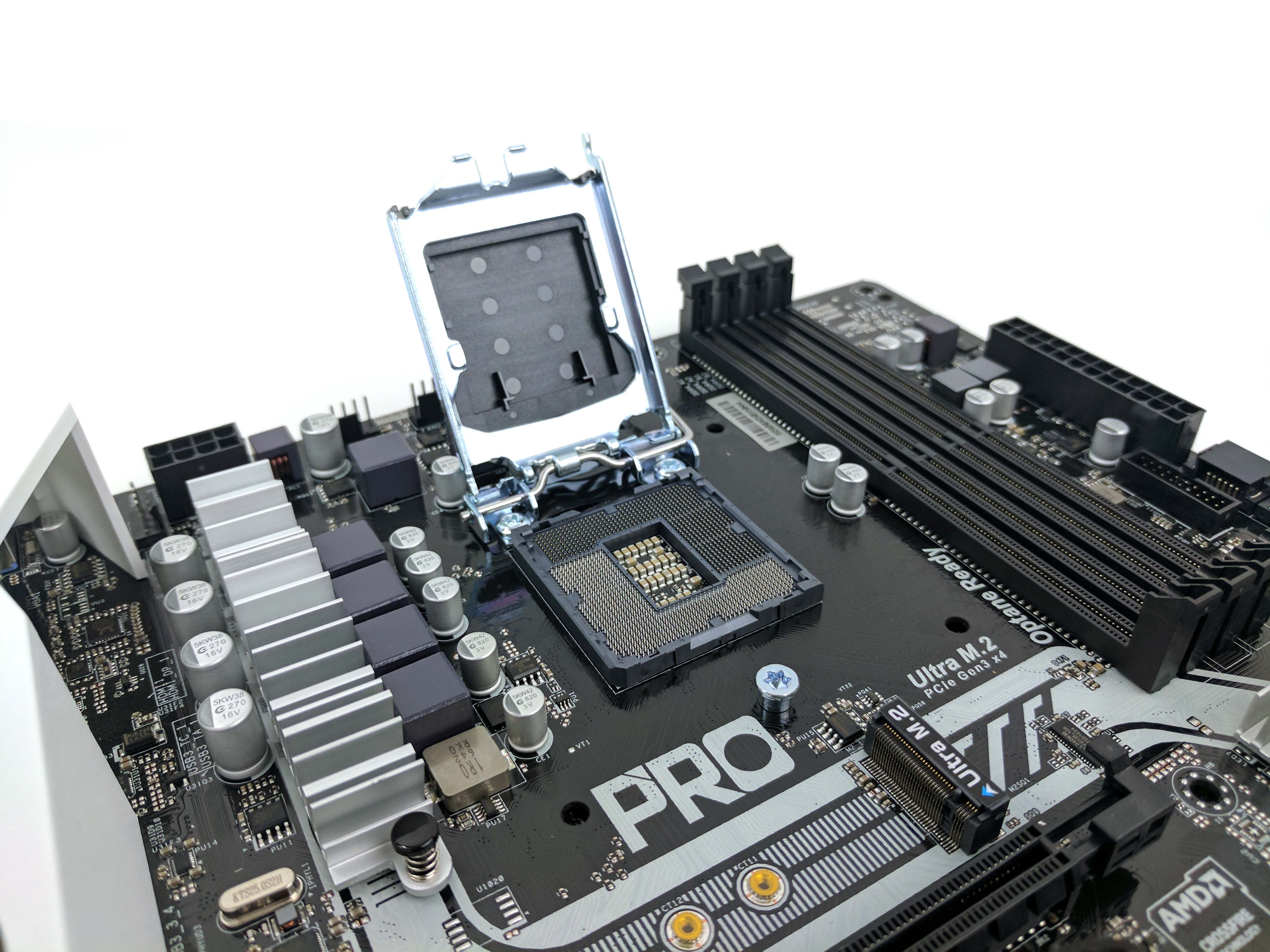
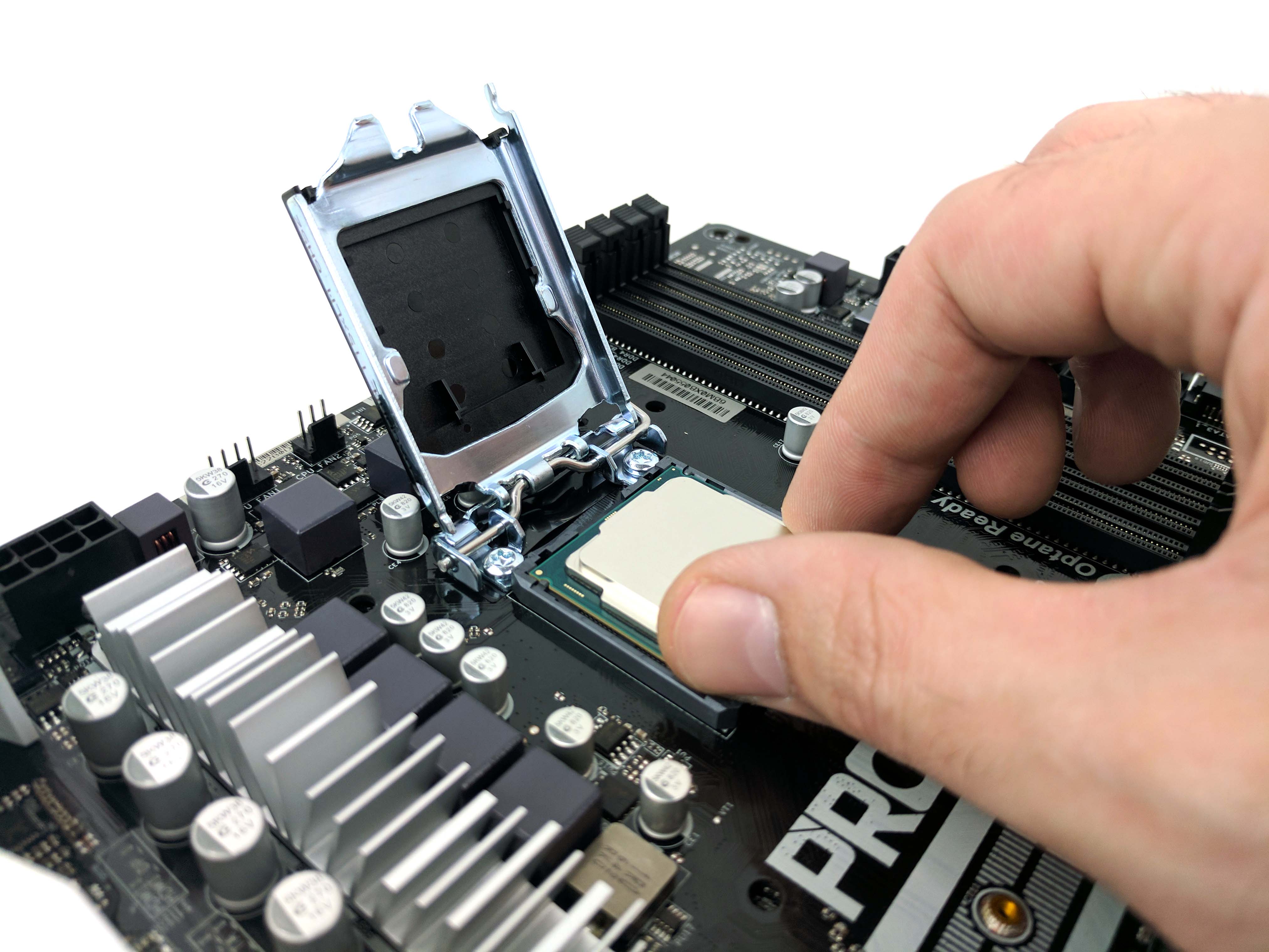
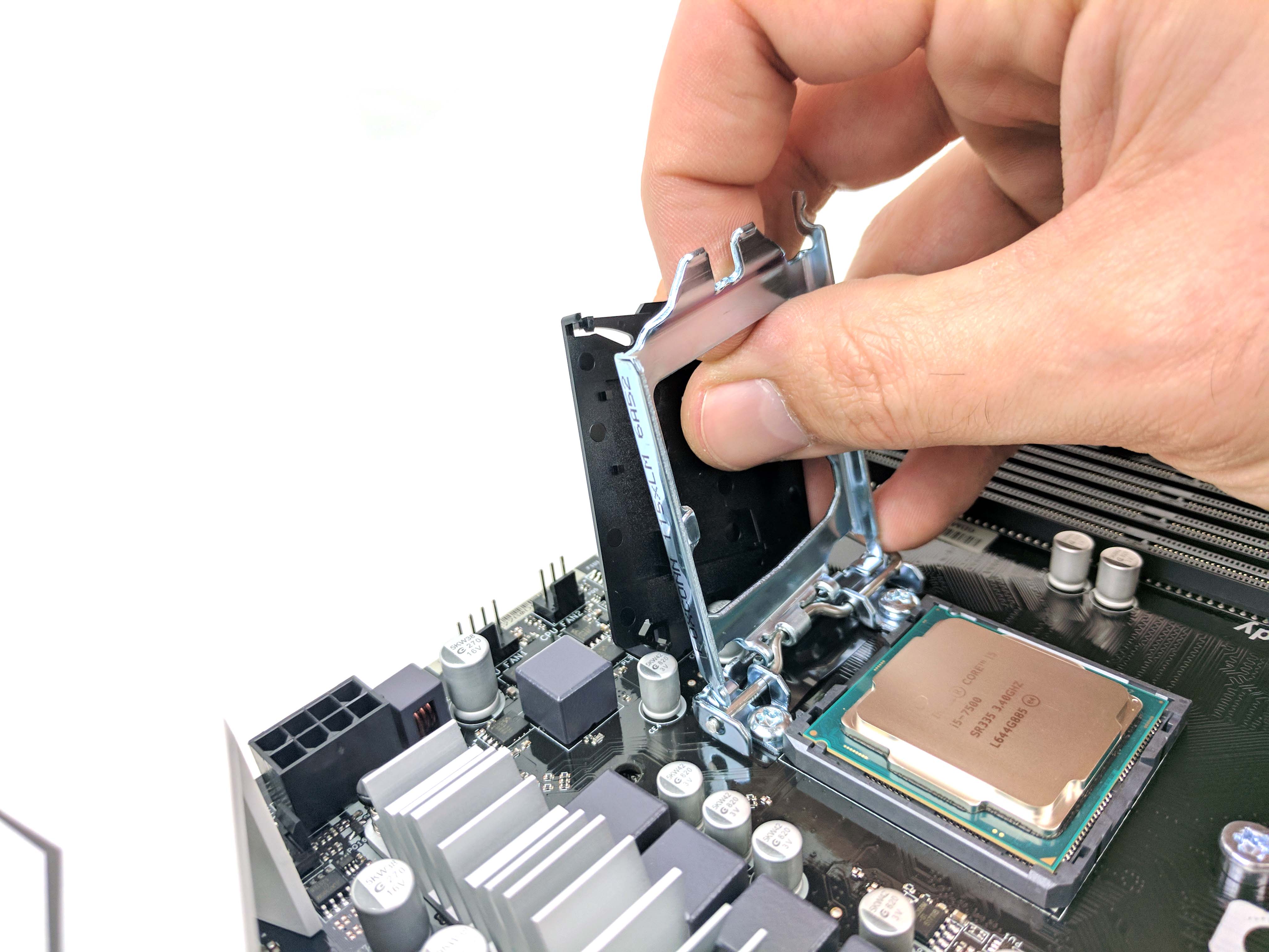
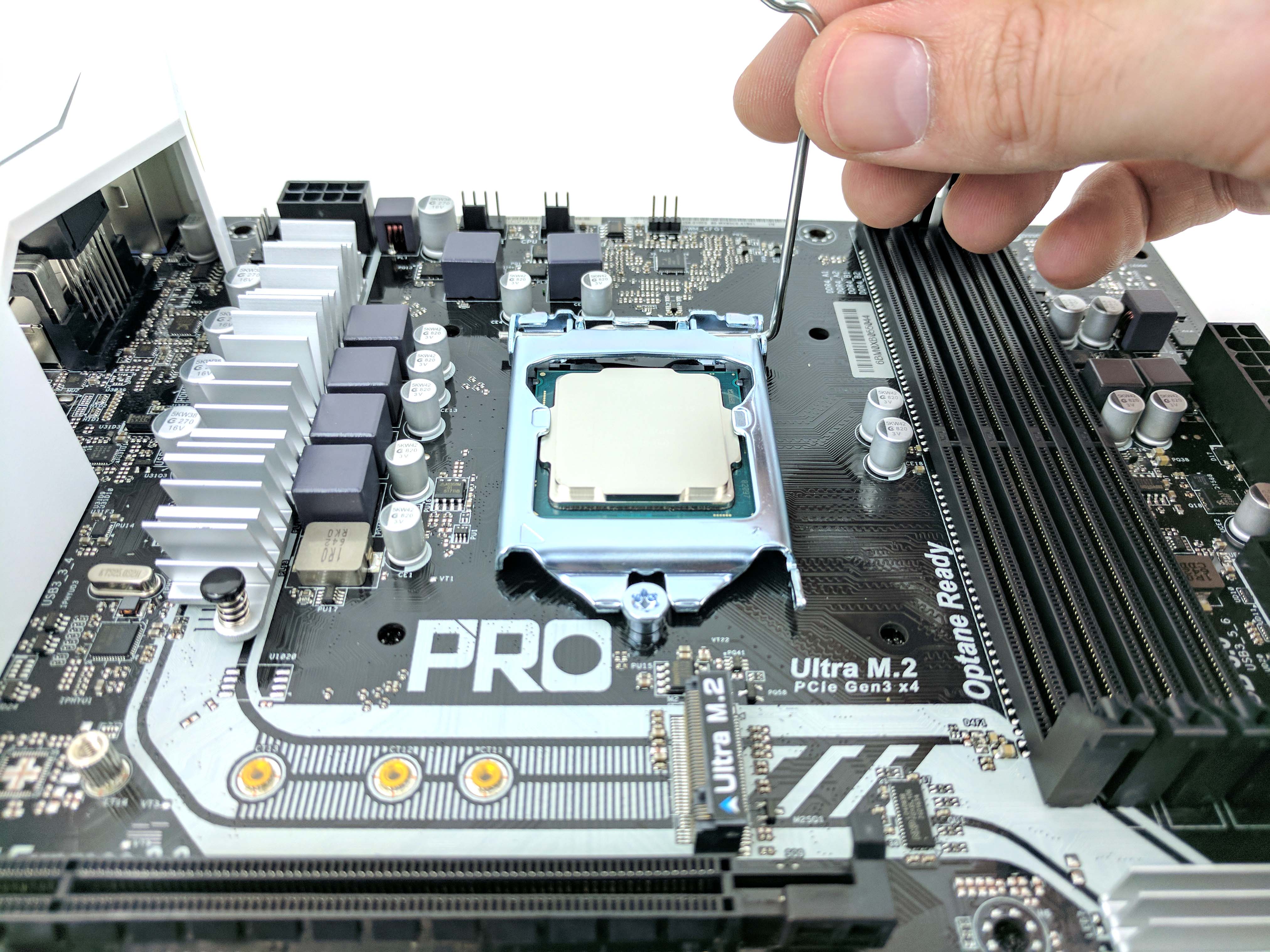
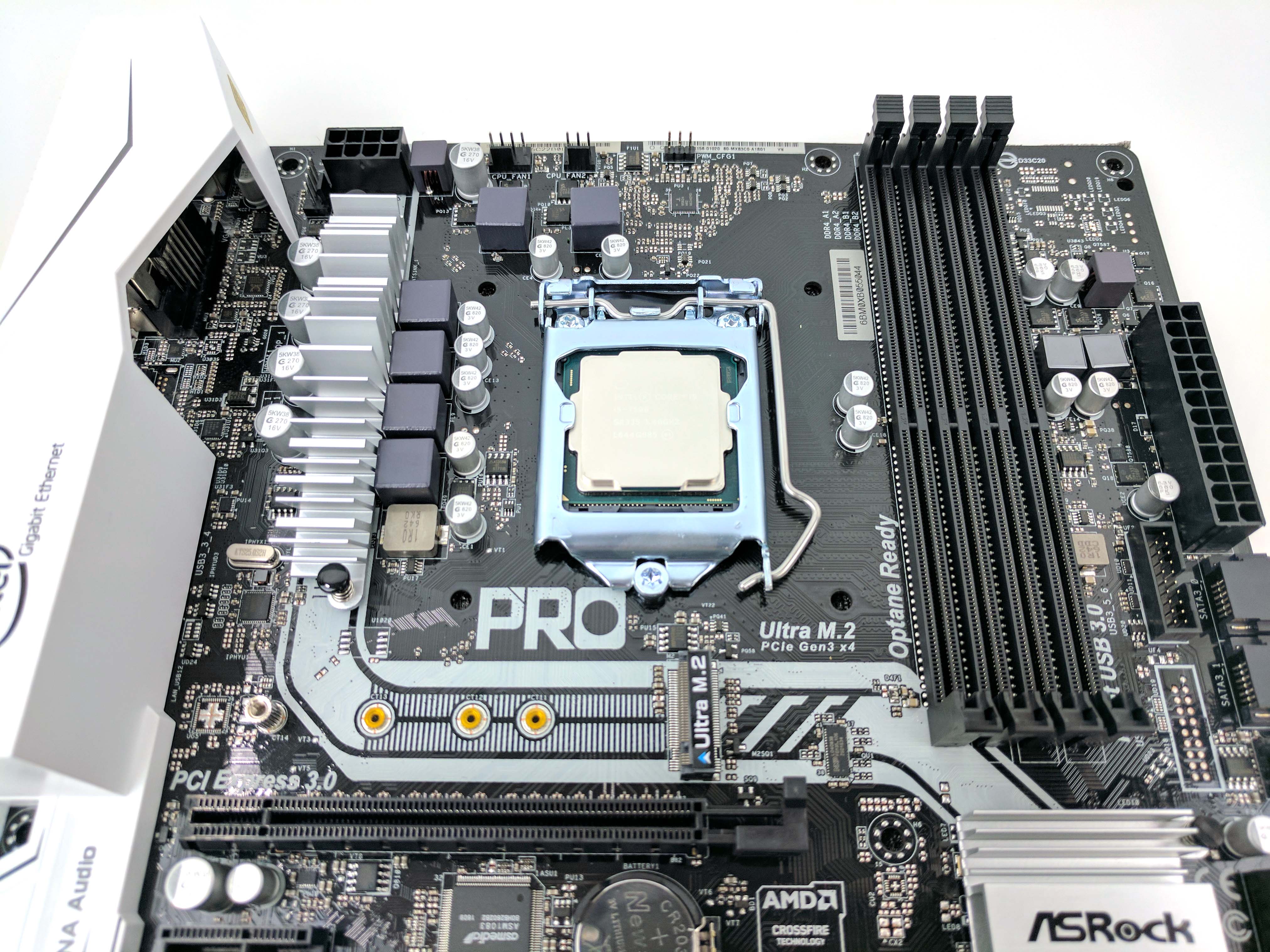
Take the Intel Core i5-7500 out of its box, but keep it in the plastic cover for now. Also remove the CPU cooler and set it aside. Raise the retention arm on the motherboard’s CPU socket to raise the clamp and expose the socket (see the 4th and 5th picture below). Carefully remove the processor from its plastic cover, line up the notches in the CPU and socket (6th picture below), and lower it into the motherboard. Remove the clamp’s plastic protective cover and position it over the CPU and under the retention bolt (see 7th picture). Lower the retention arm and attach it to the hook to keep it down.
The Cooler & Memory
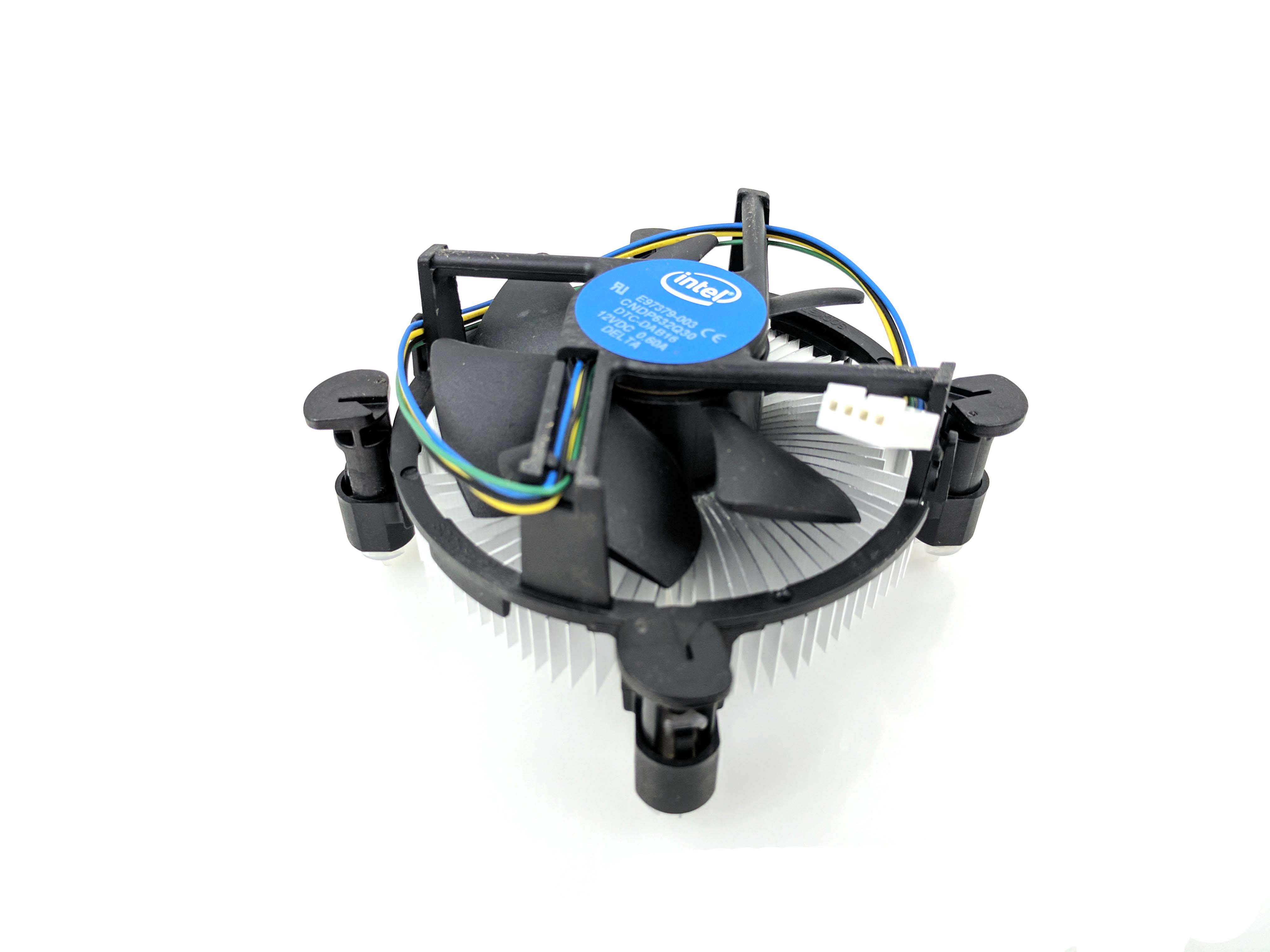
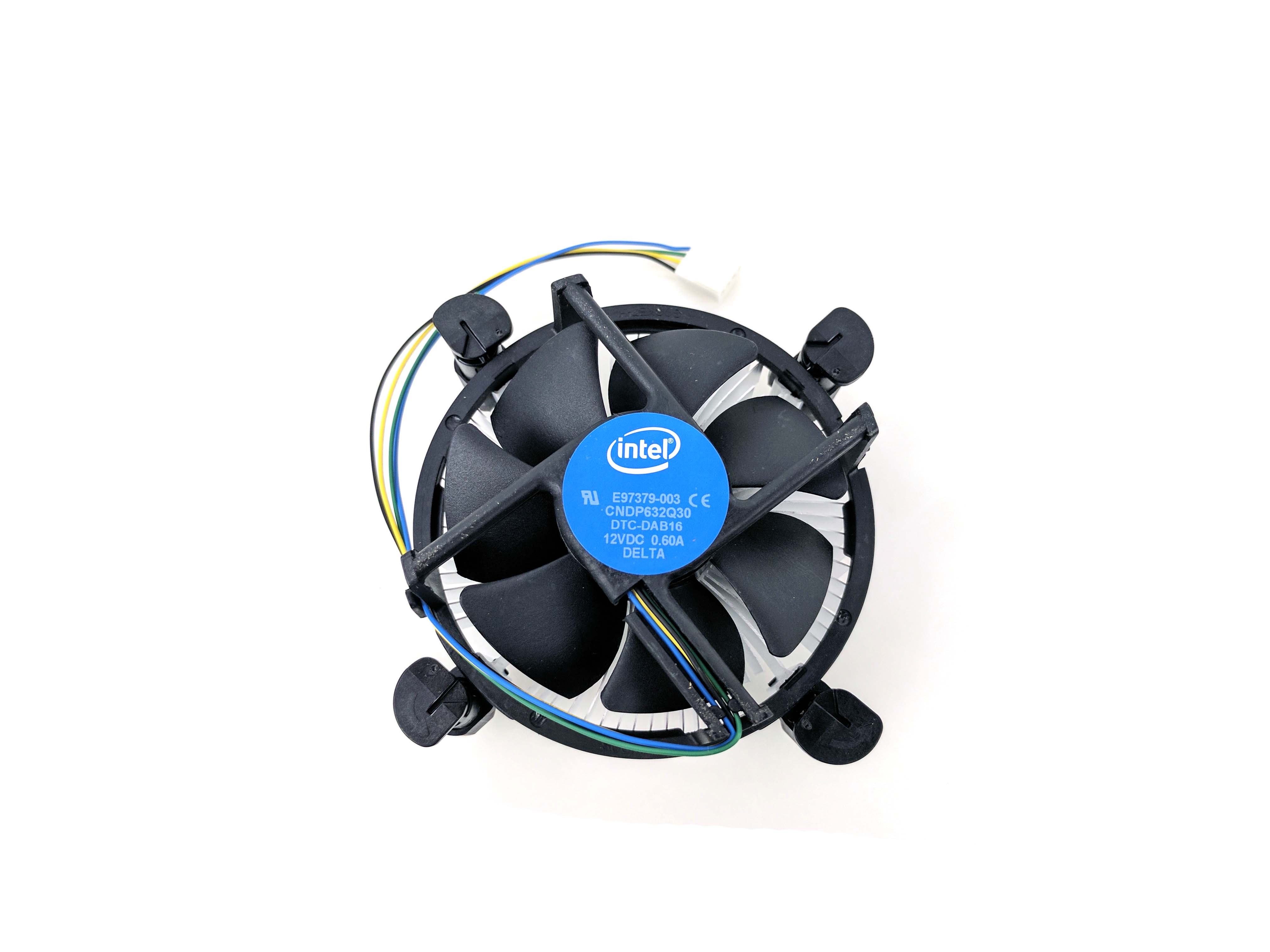
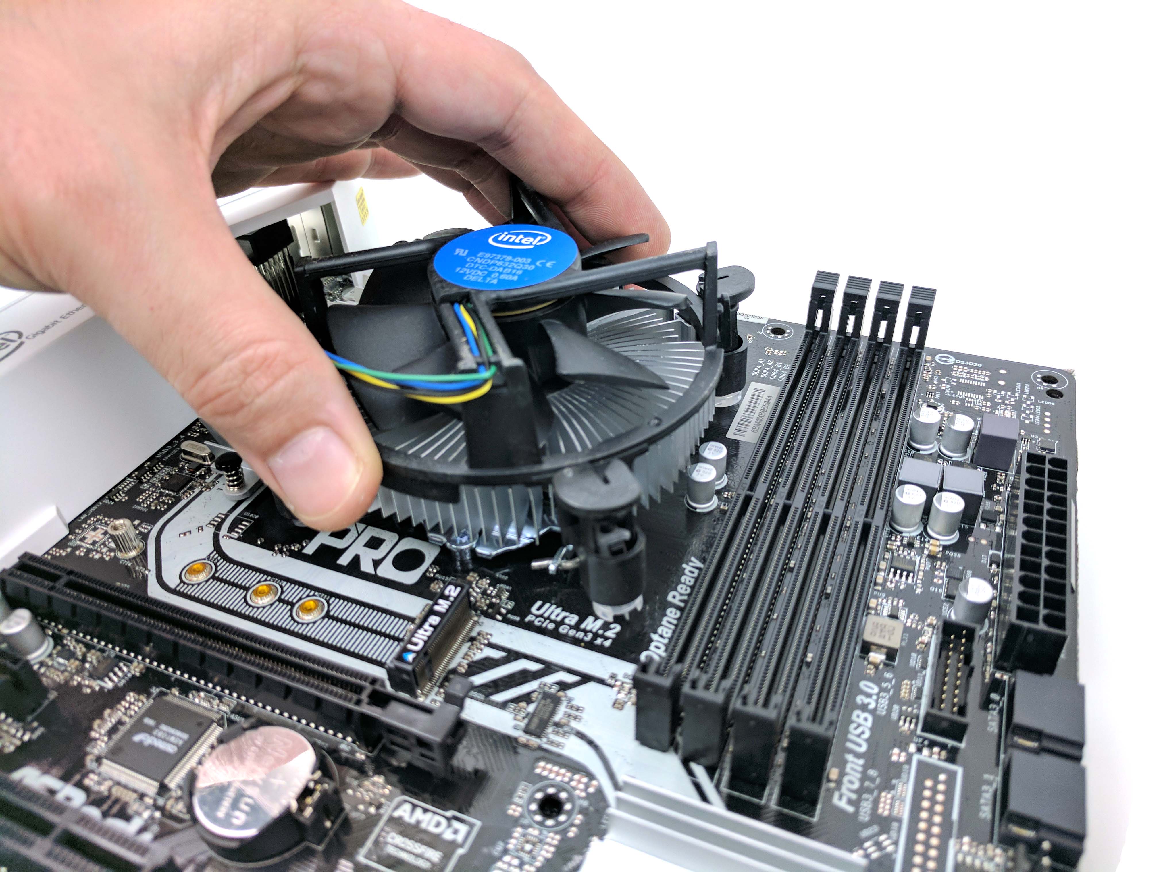
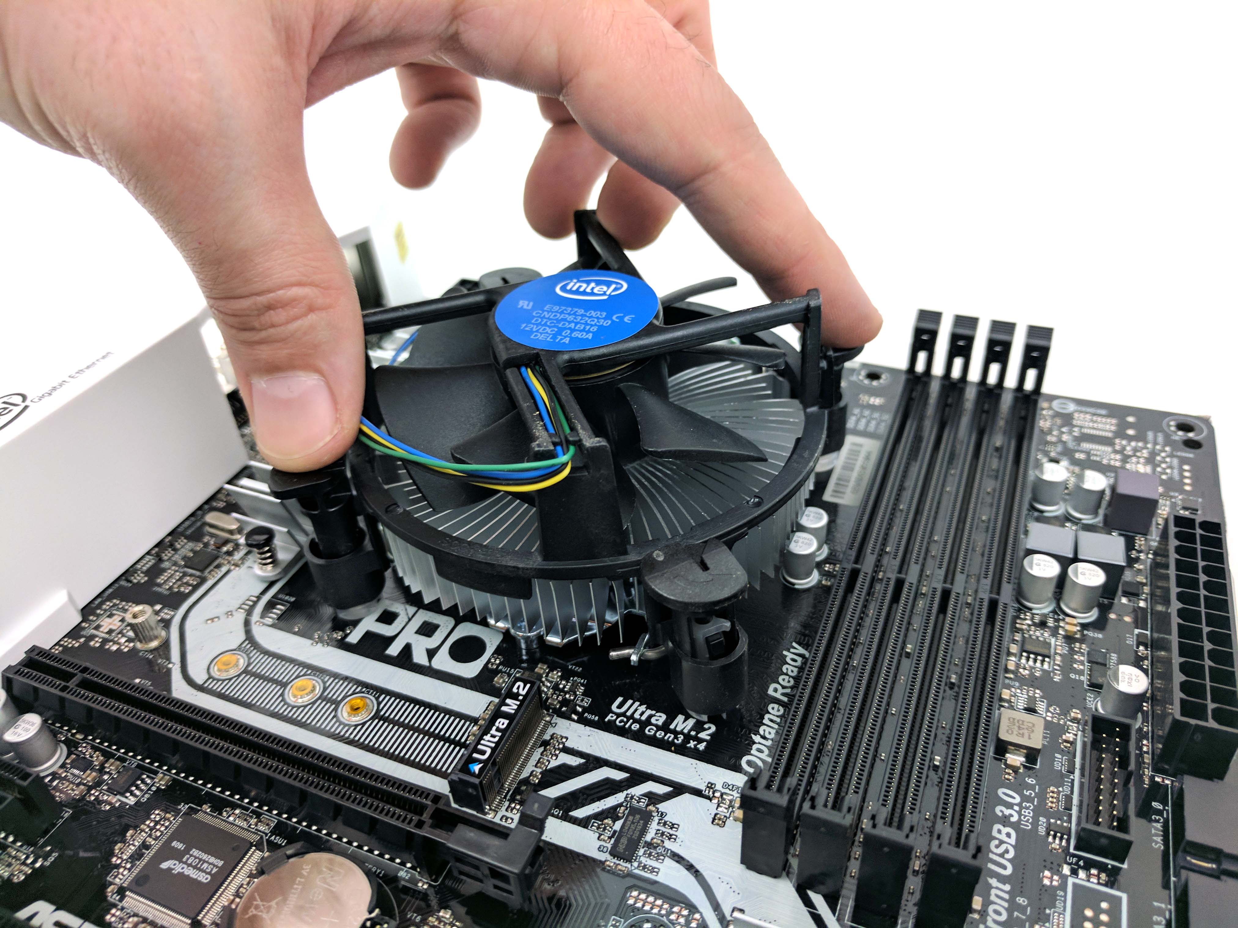
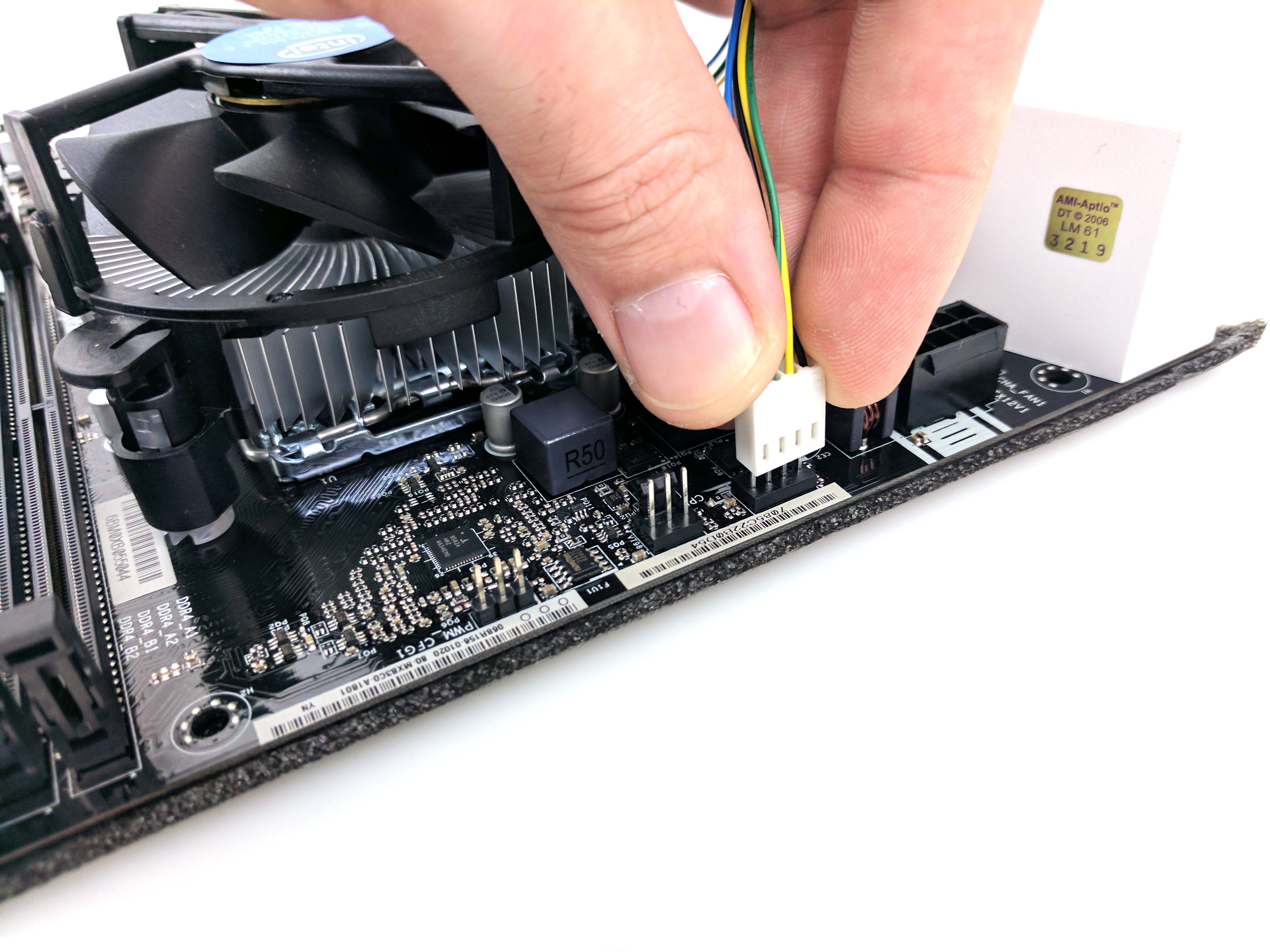
Guide the CPU cooler’s fan cable out of the fan blades and loosen it so that the fan spins freely. You can keep the wire hooked to the side of the cooler as is; it will easily reach the fan port without changing it. Line up the heatsink’s posts to the motherboard’s holes (so that the fan cable can reach its ports on the motherboard) and press down, two at a time (diagonally, illustrated in the 4th picture below), to secure the cooler to the processor. Plug in the CPU fan cable to the CPU FAN 1 leads (slide 5 below).
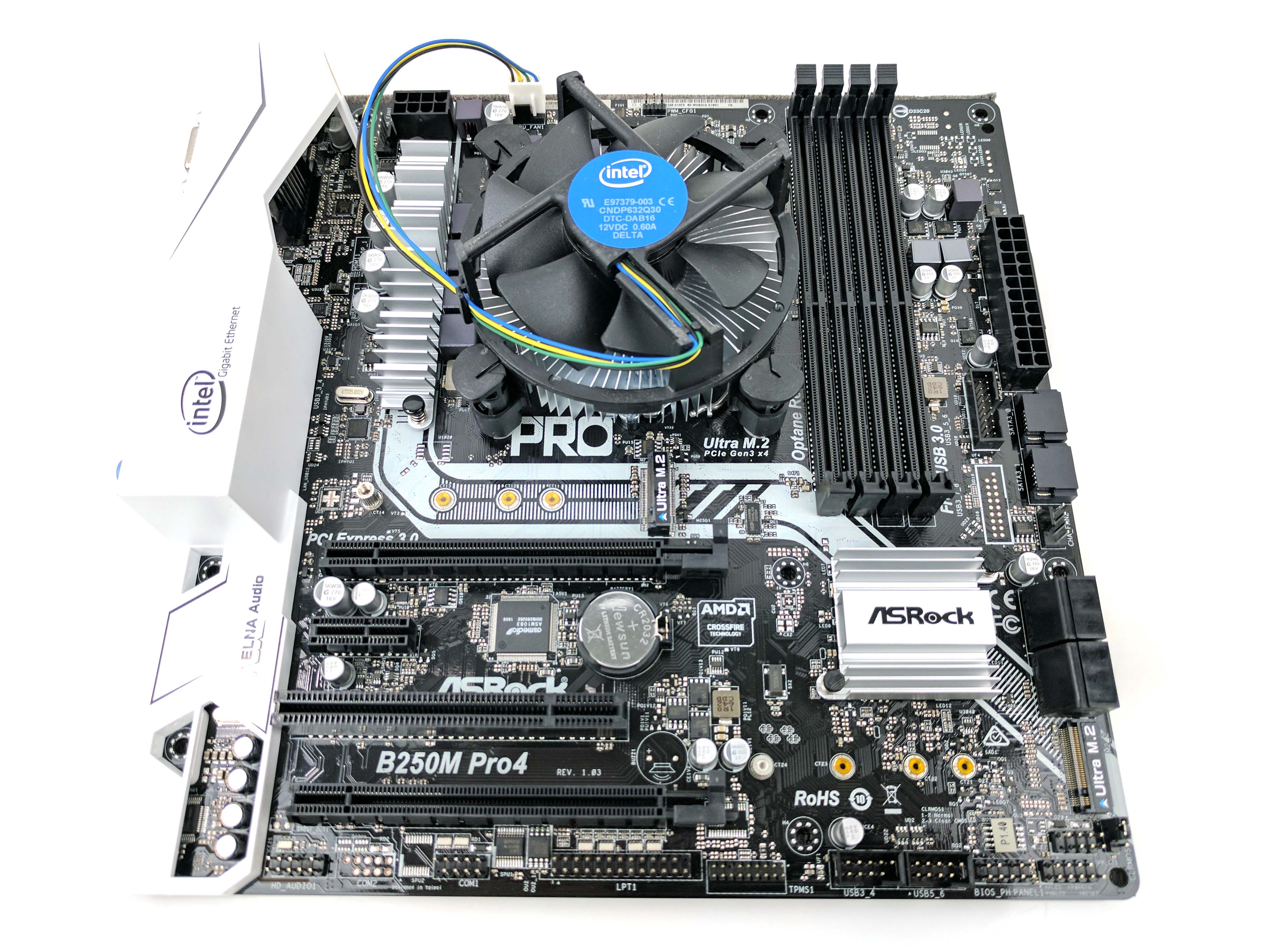
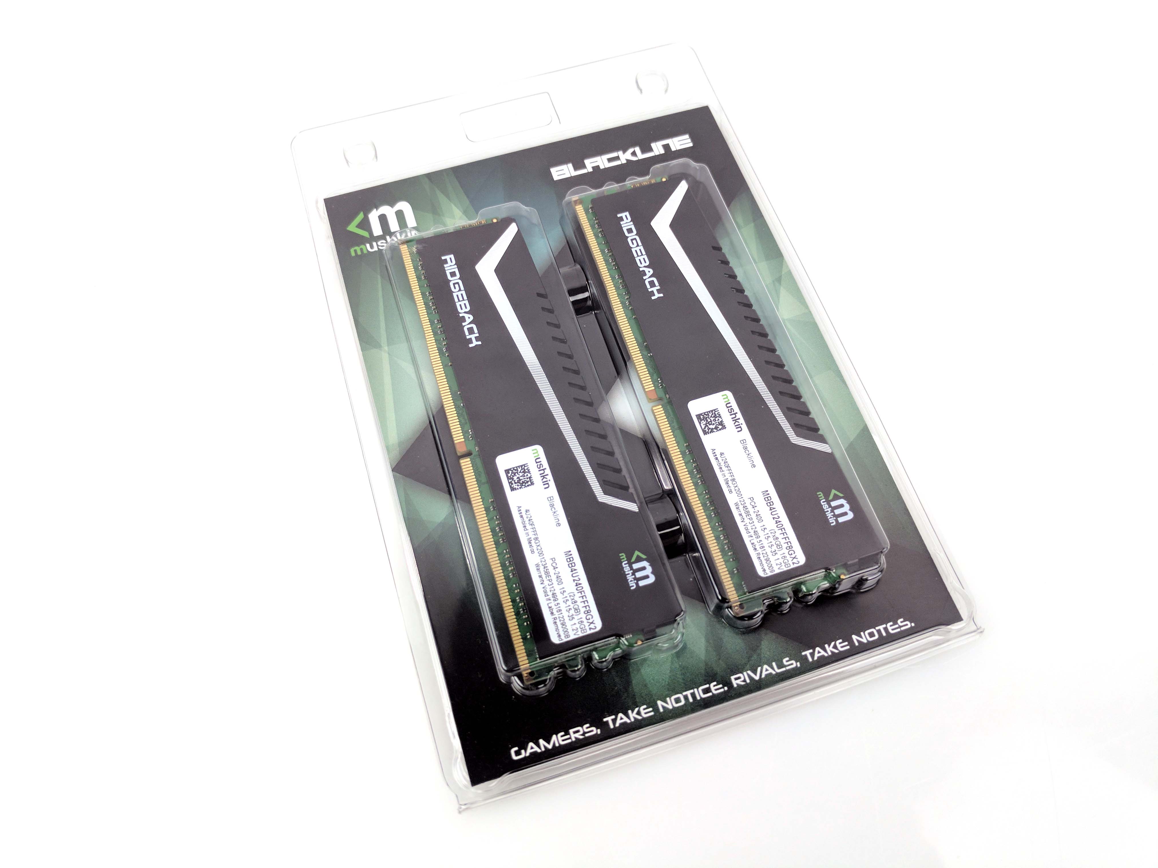
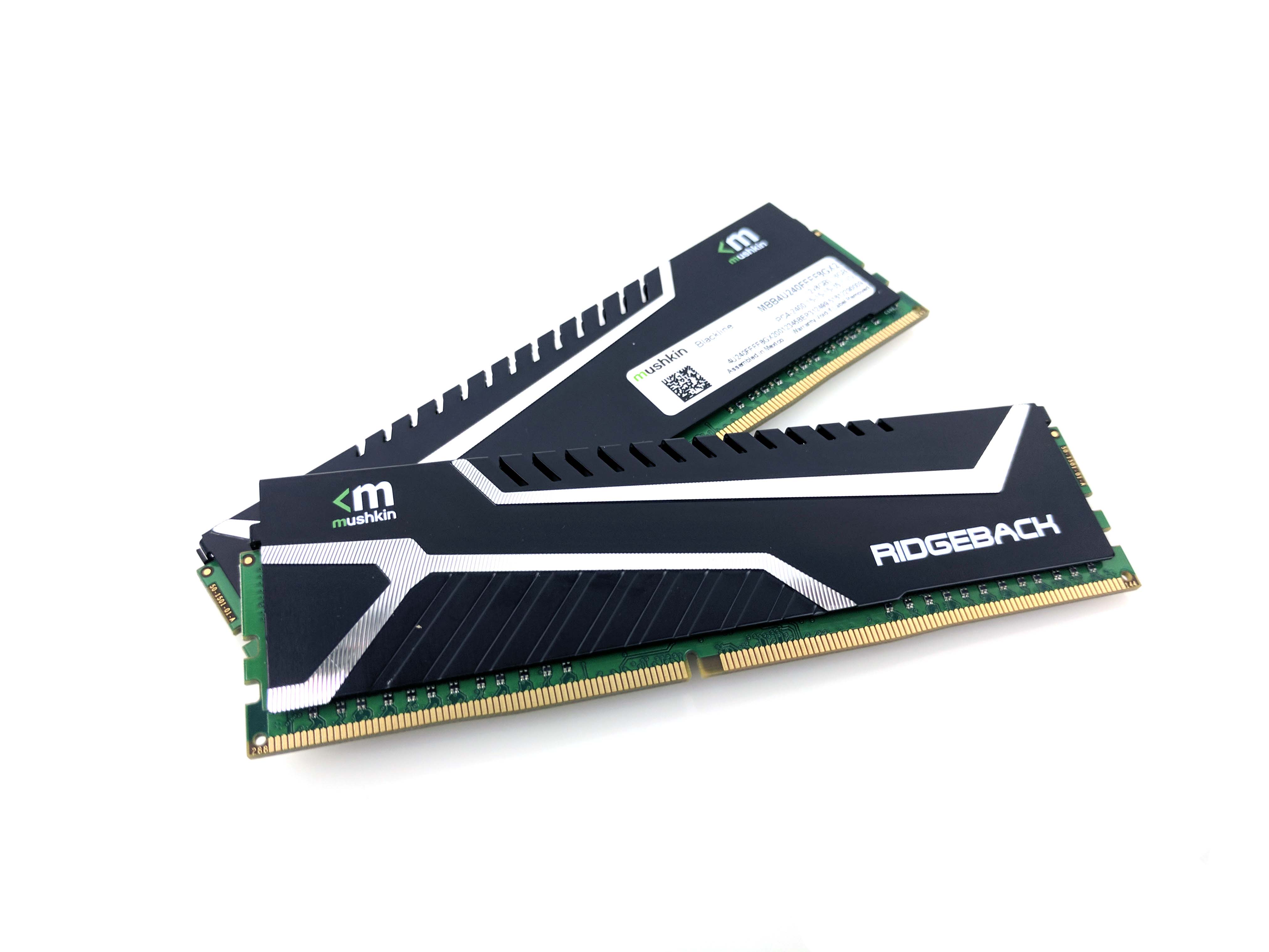
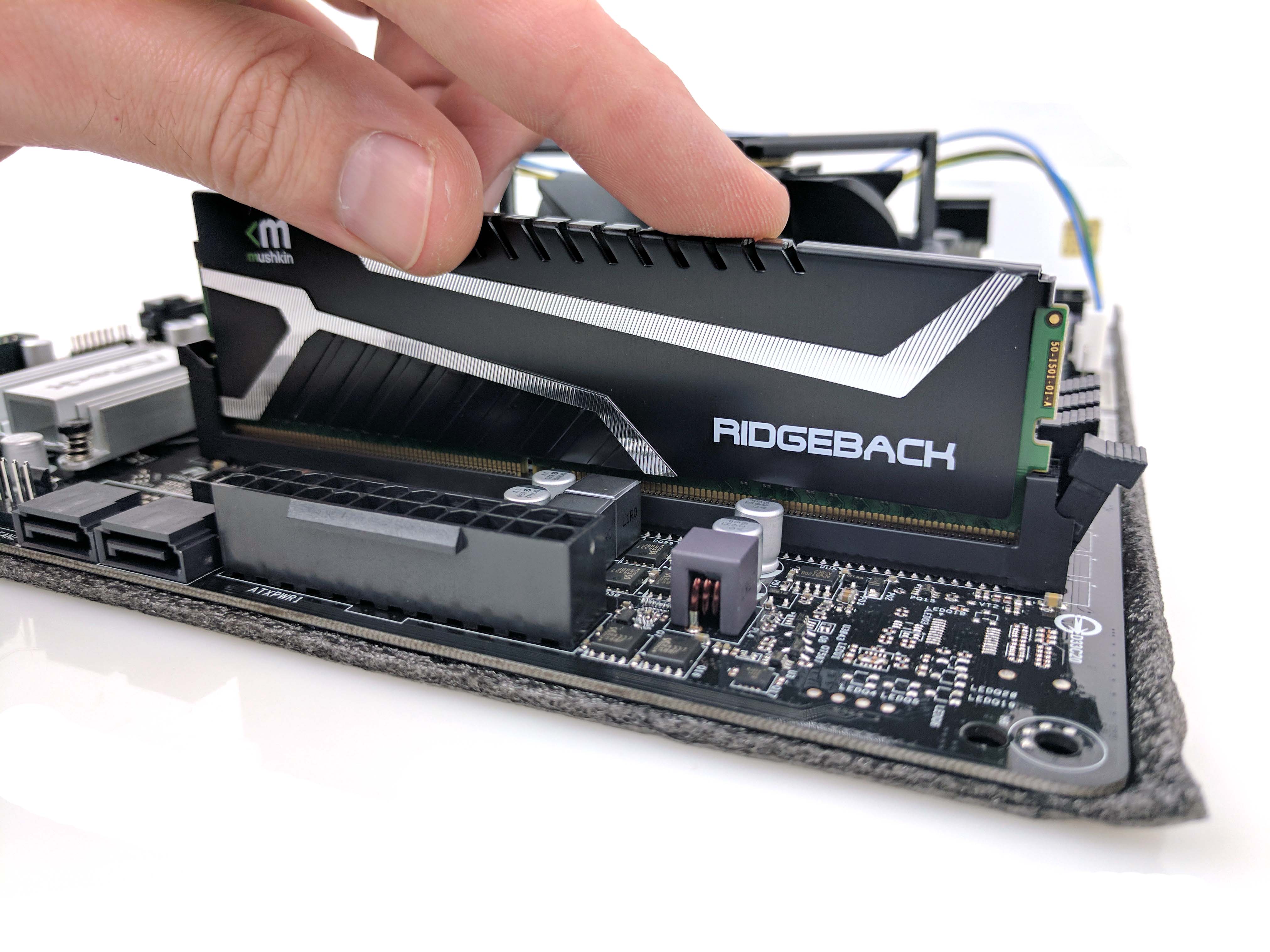
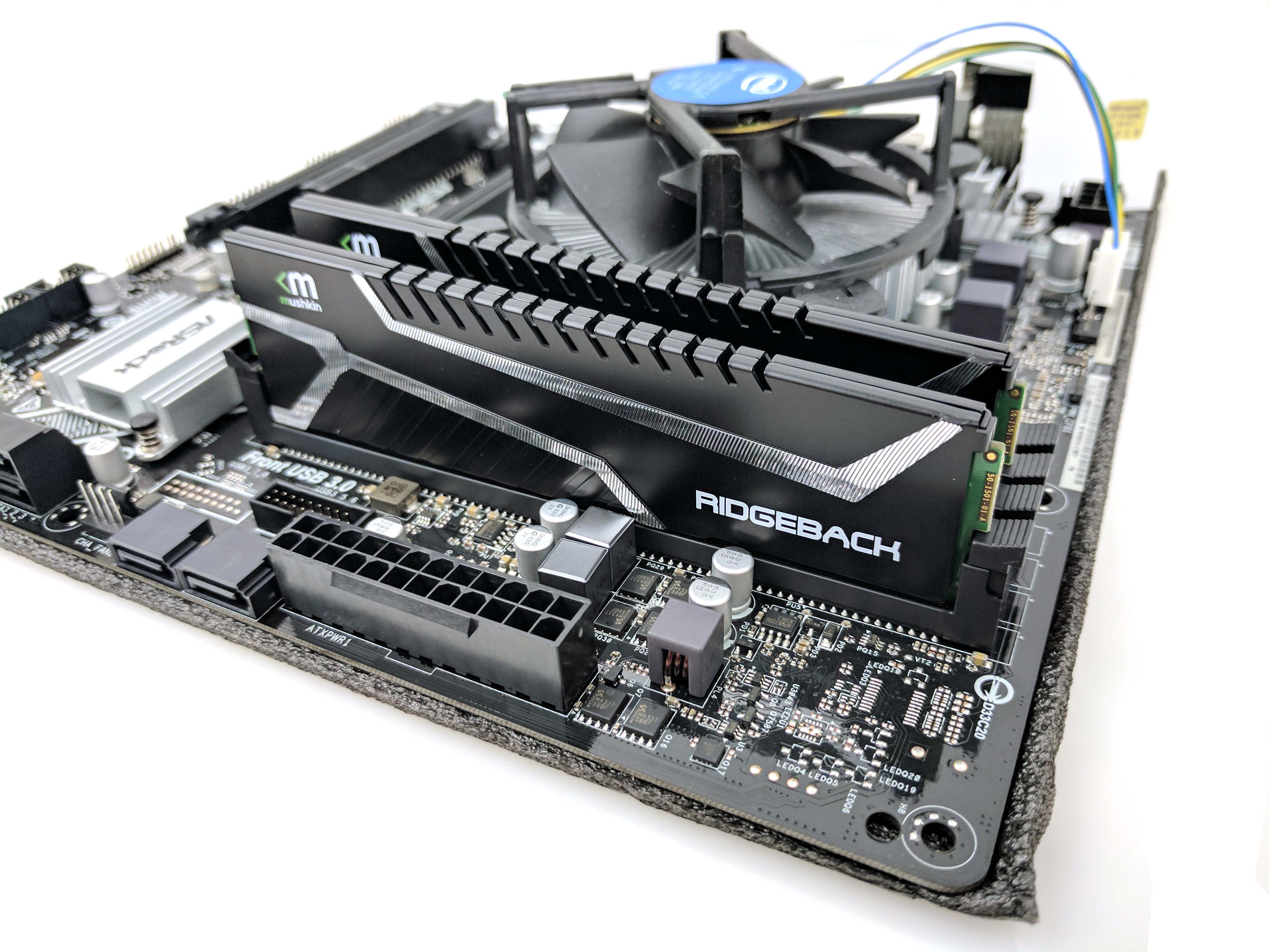
Remove the 16GB (2 x 8GB) kit of Mushkin Blackline DDR4-2400 RAM from its packaging. Unlock the clips at the top of the second and fourth DIMM slots from the left, line up the notches in the module with the memory slot, and press down to secure the RAM to the motherboard (see the 9th picture above). The clips should lock in place by themselves.
Component Installation
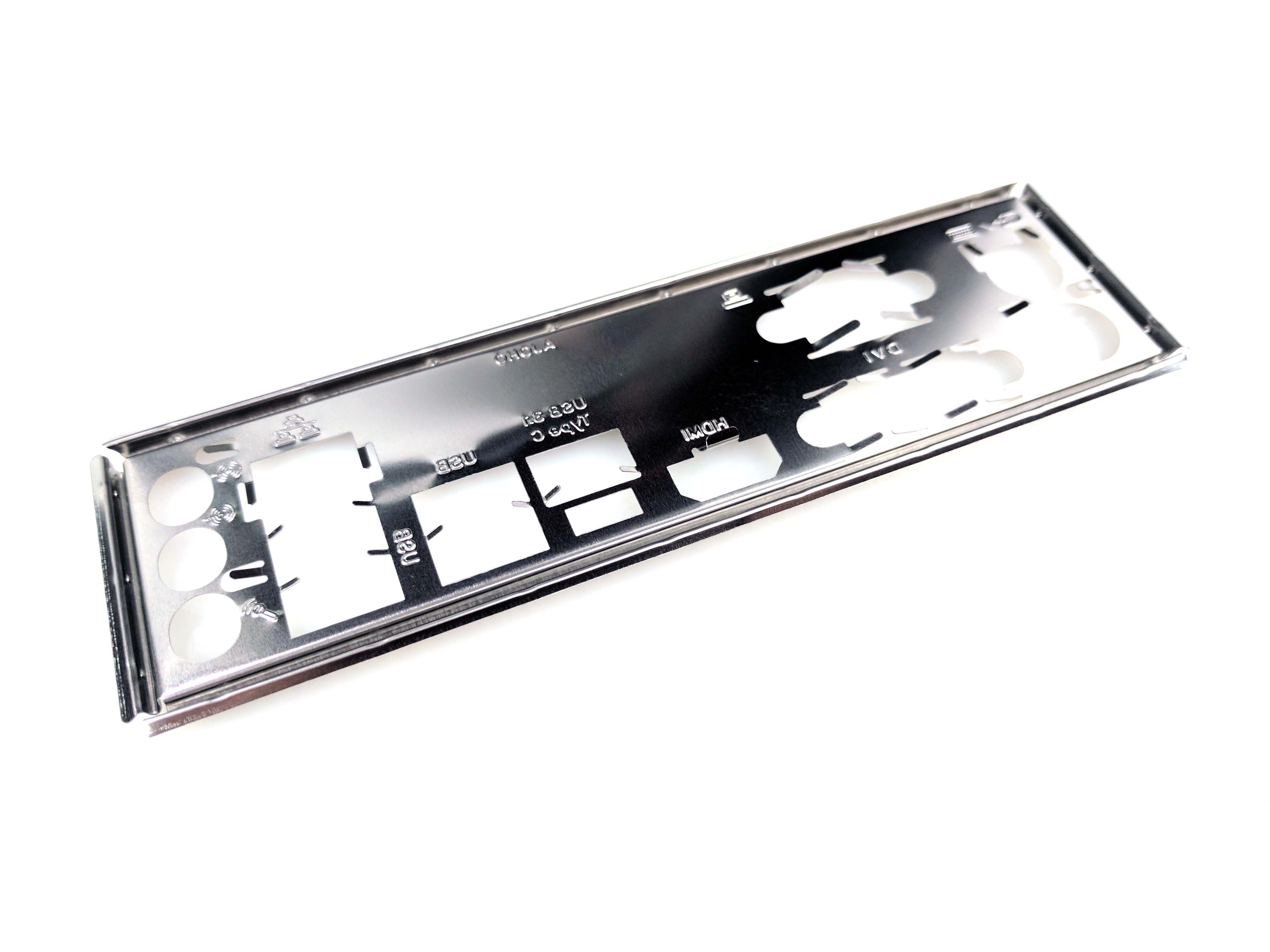
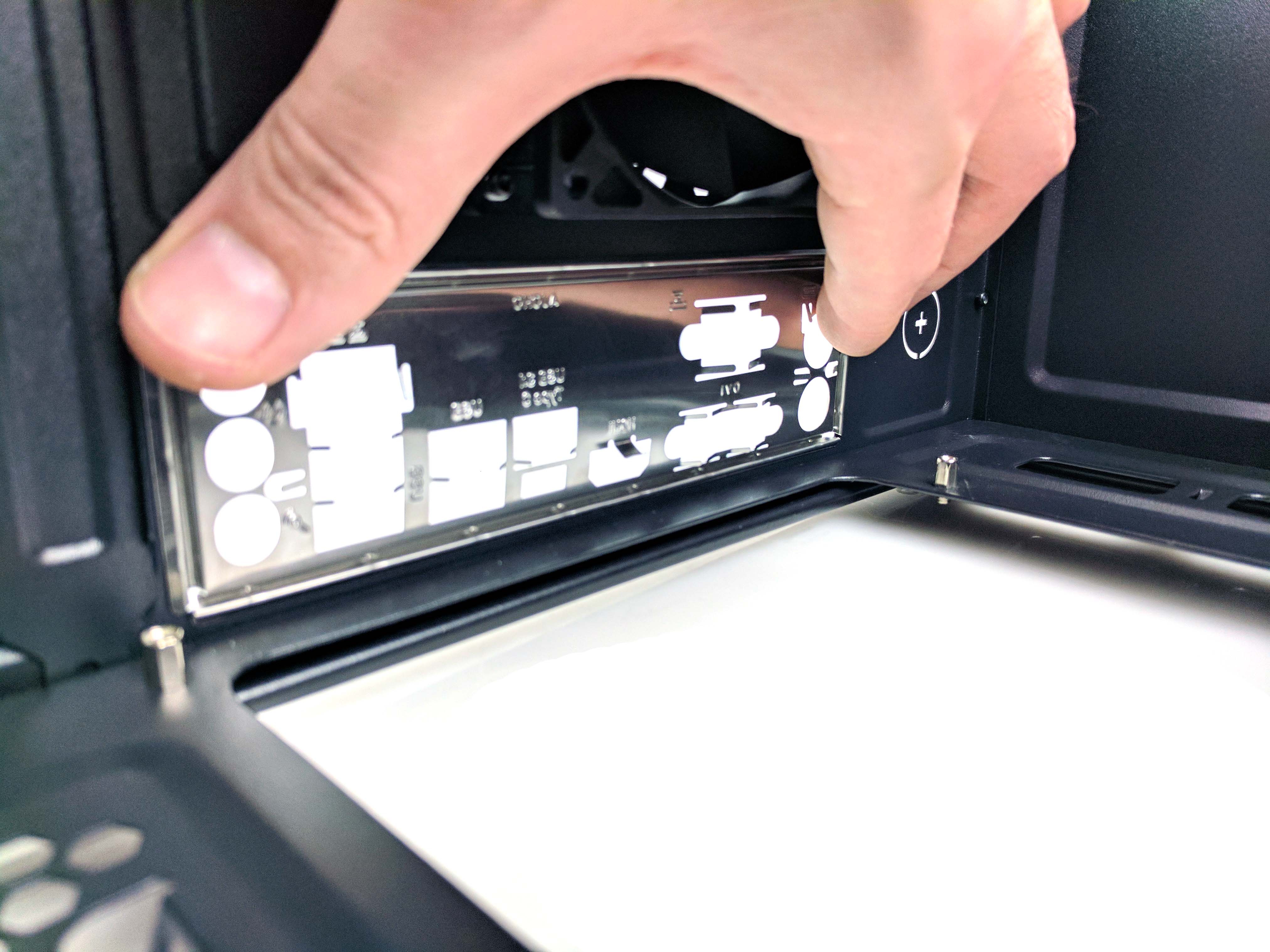
Next, we’ll install the motherboard and remaining components. Attach the motherboard’s rear I/O plate to the case (see slide 2 below). The sidewall of the chassis is somewhat flimsy, and it may be difficult at first, but we found that persistence is key with this particular case.
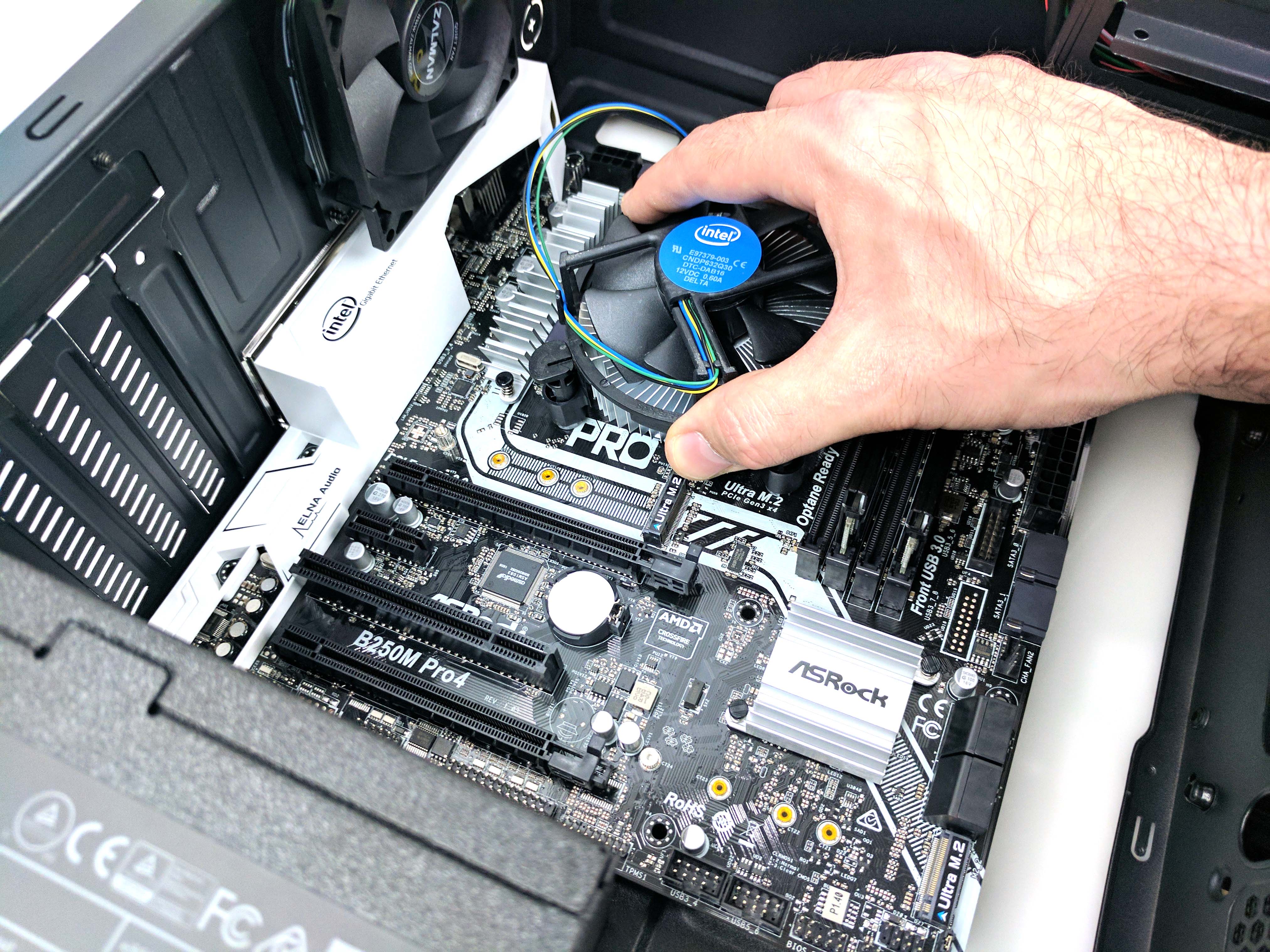
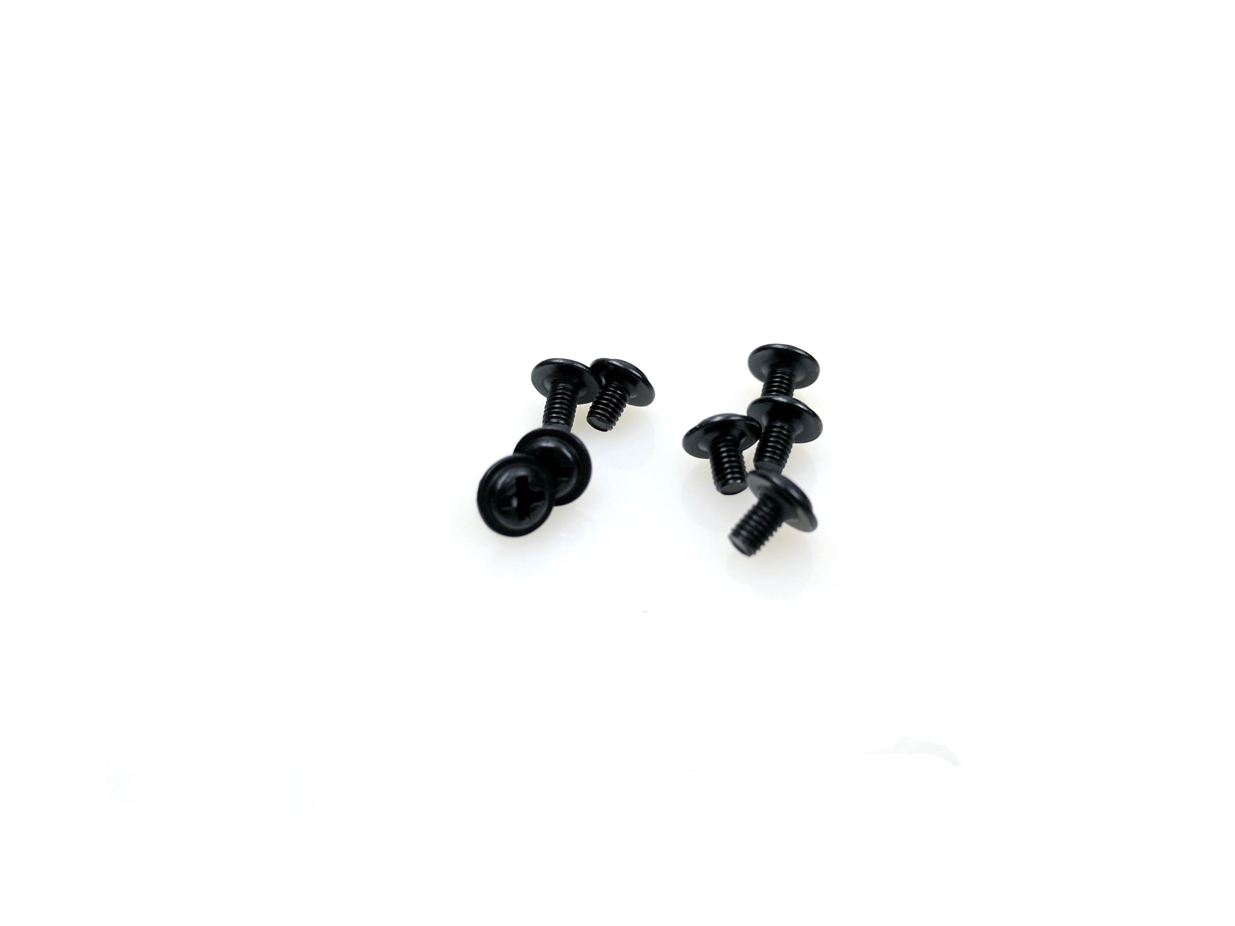
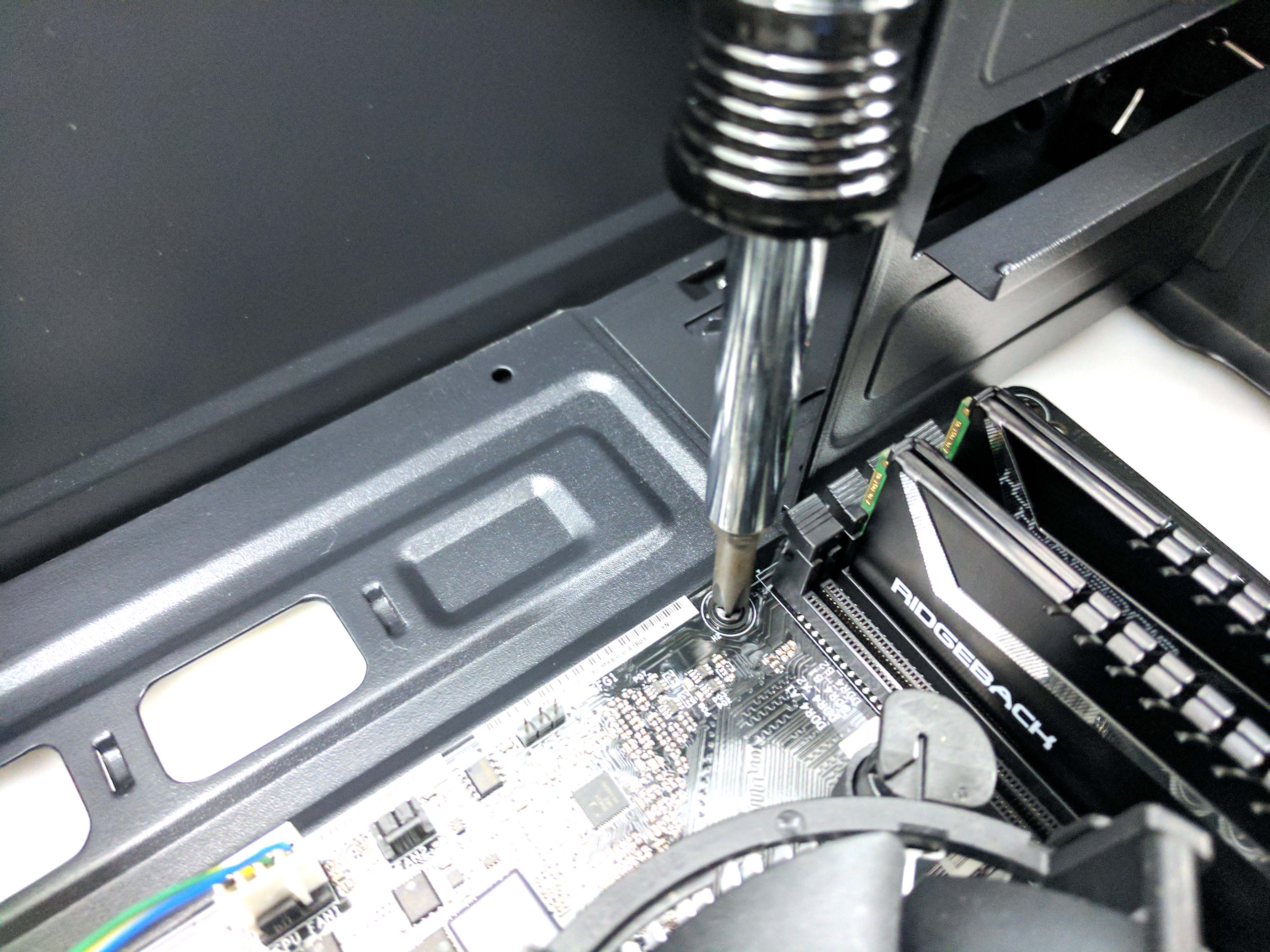
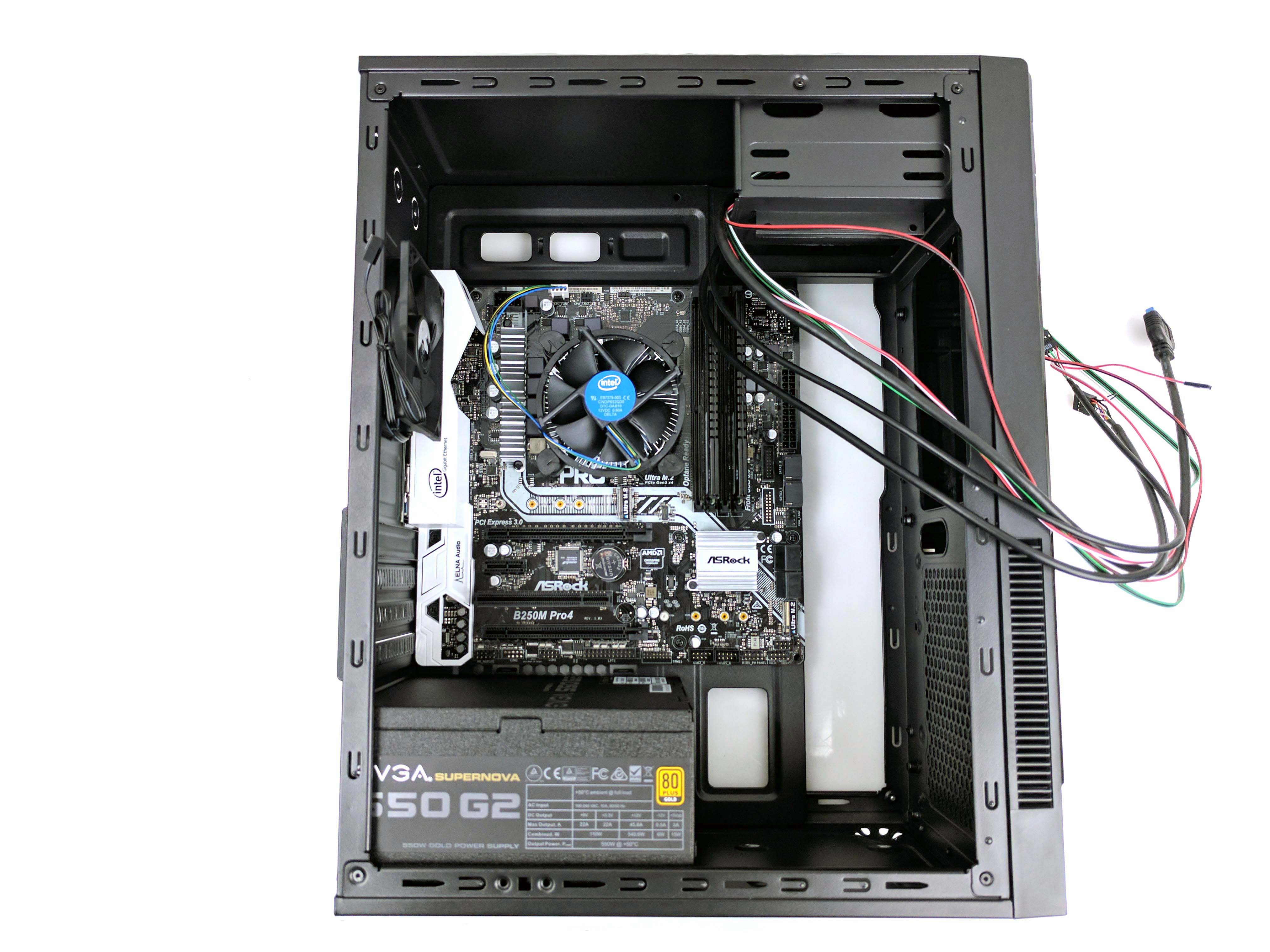
Carefully lower the motherboard into the chassis (the CPU cooler makes an adequate gripping point; see the 3rd picture above) and line up the case’s stand offs with the holes. Also make sure that the rear I/O ports are lined up properly, with nothing bending or out of place. Use the thin-threaded, rimmed screws from the hardware bag to secure the motherboard to the case (see slides 4 and 5 above).
Guide the case’s internal wiring around the memory and let it all hang down (there’s not much that can be done about the mess). Run the USB 2.0 and Audio cables under the bottom right edge of the motherboard (see the 3rd picture below) and towards their respective pins. Attach them both to the motherboard.
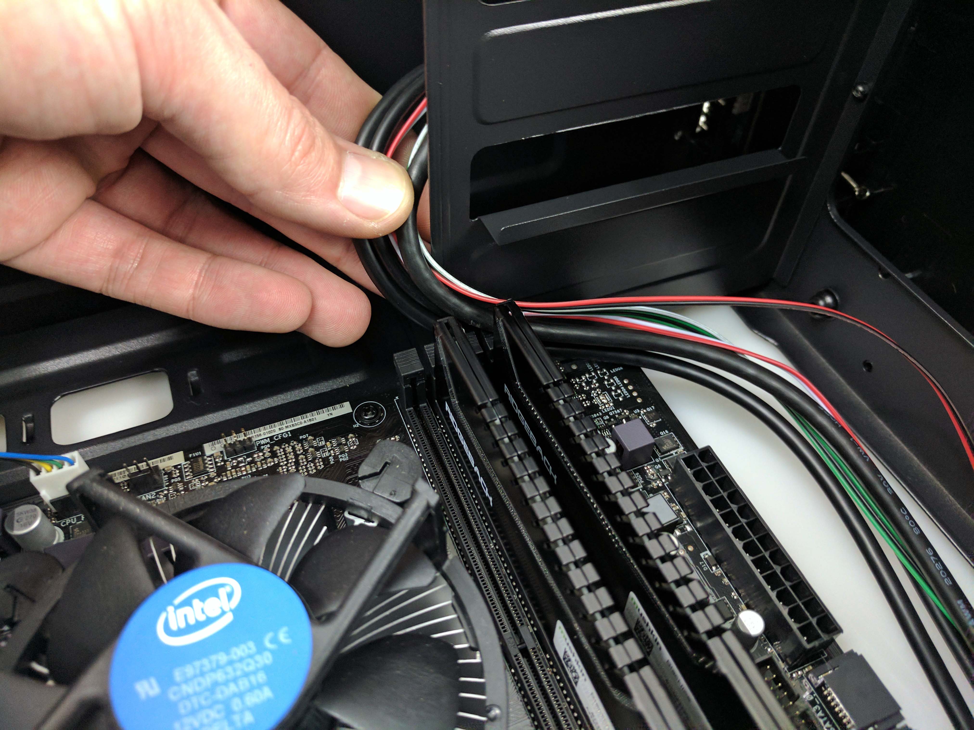
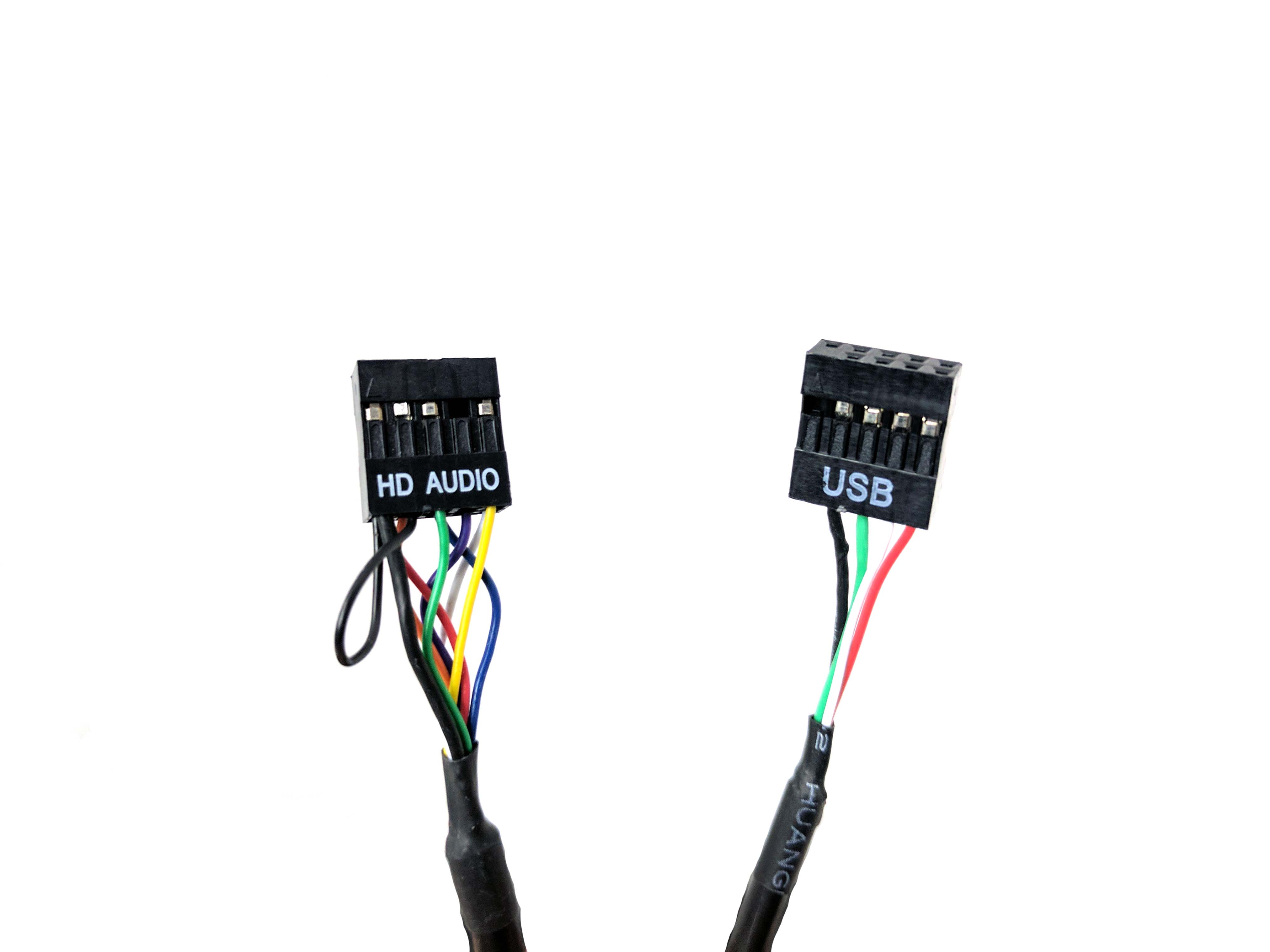
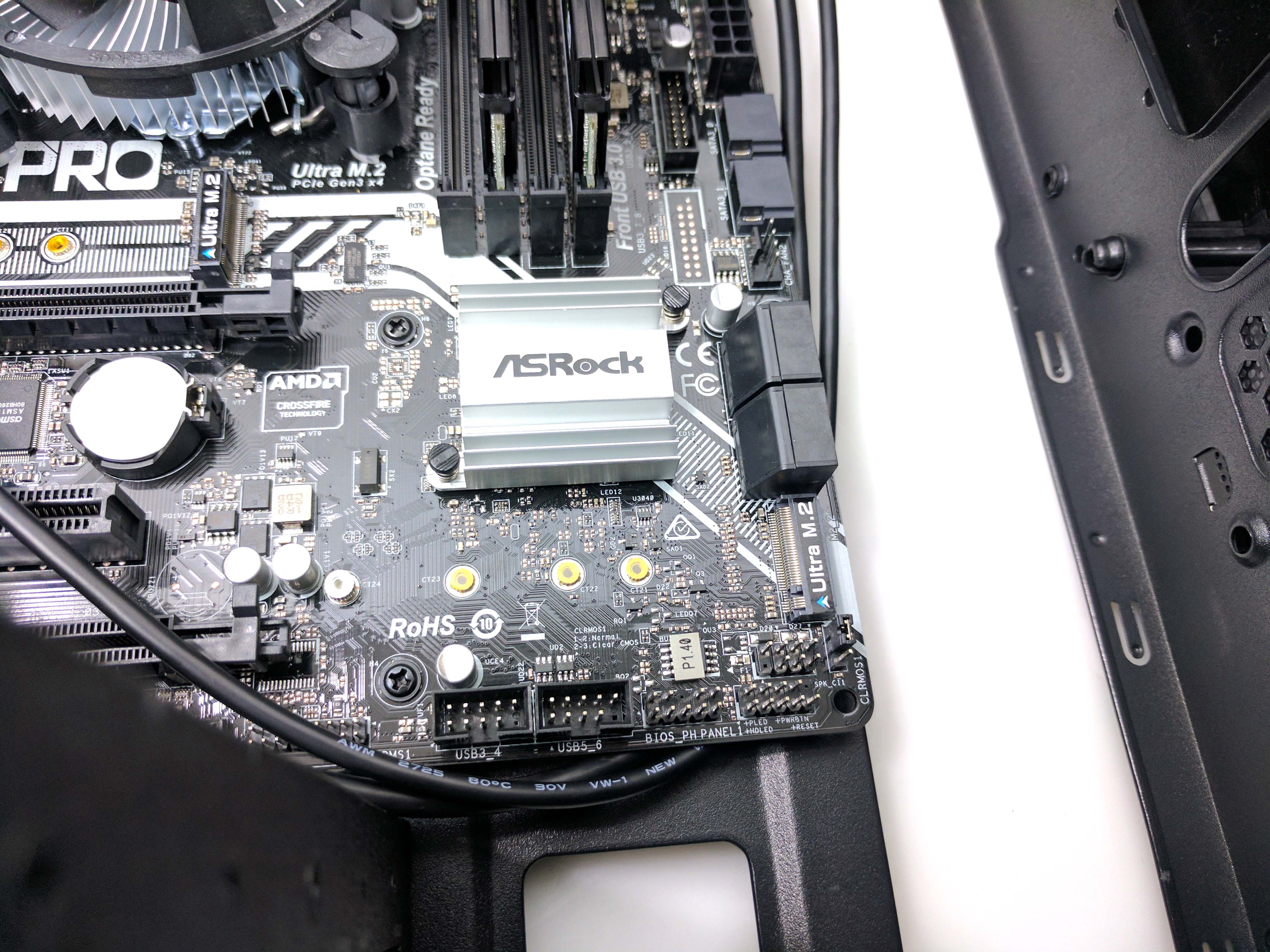
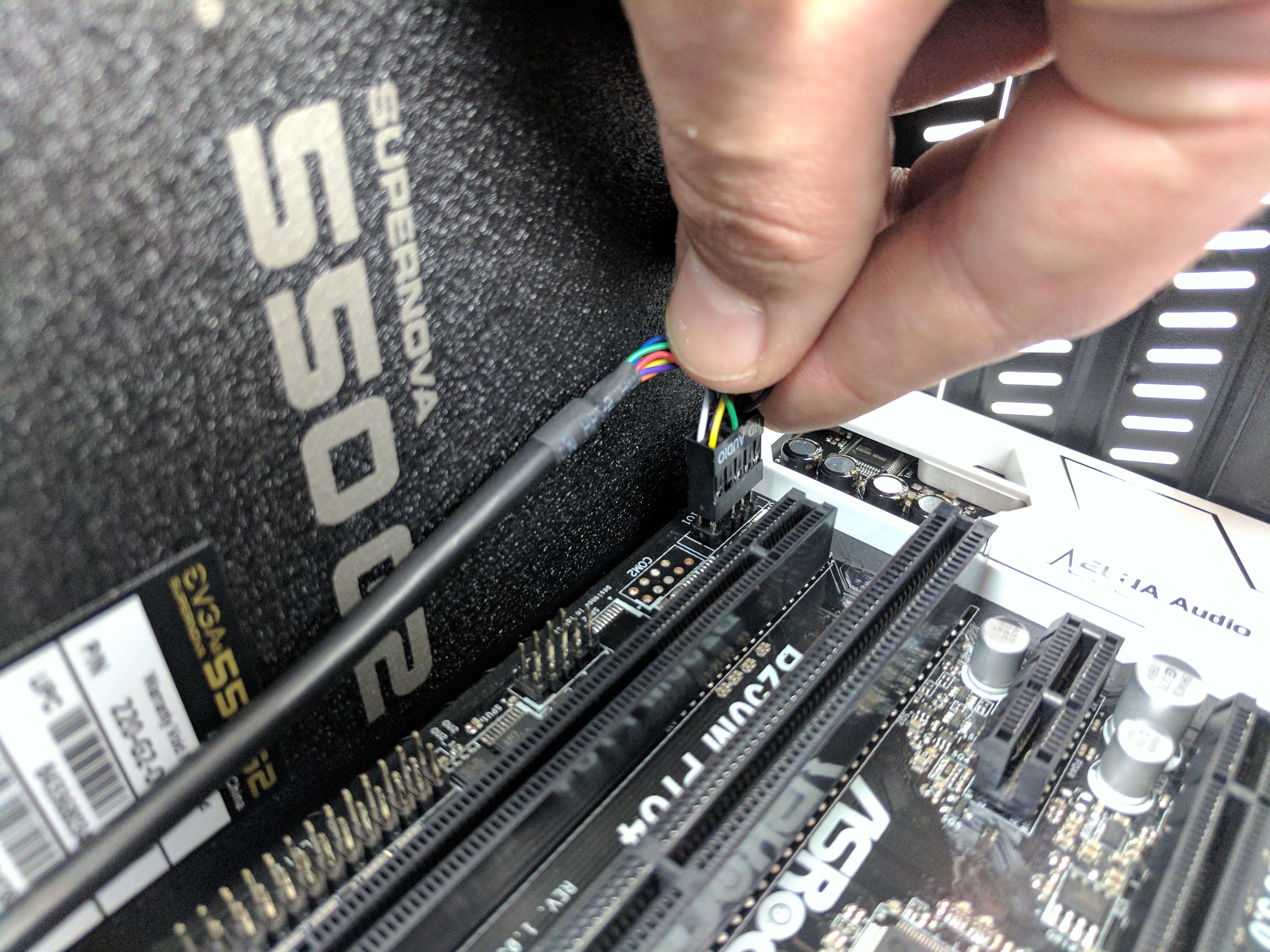
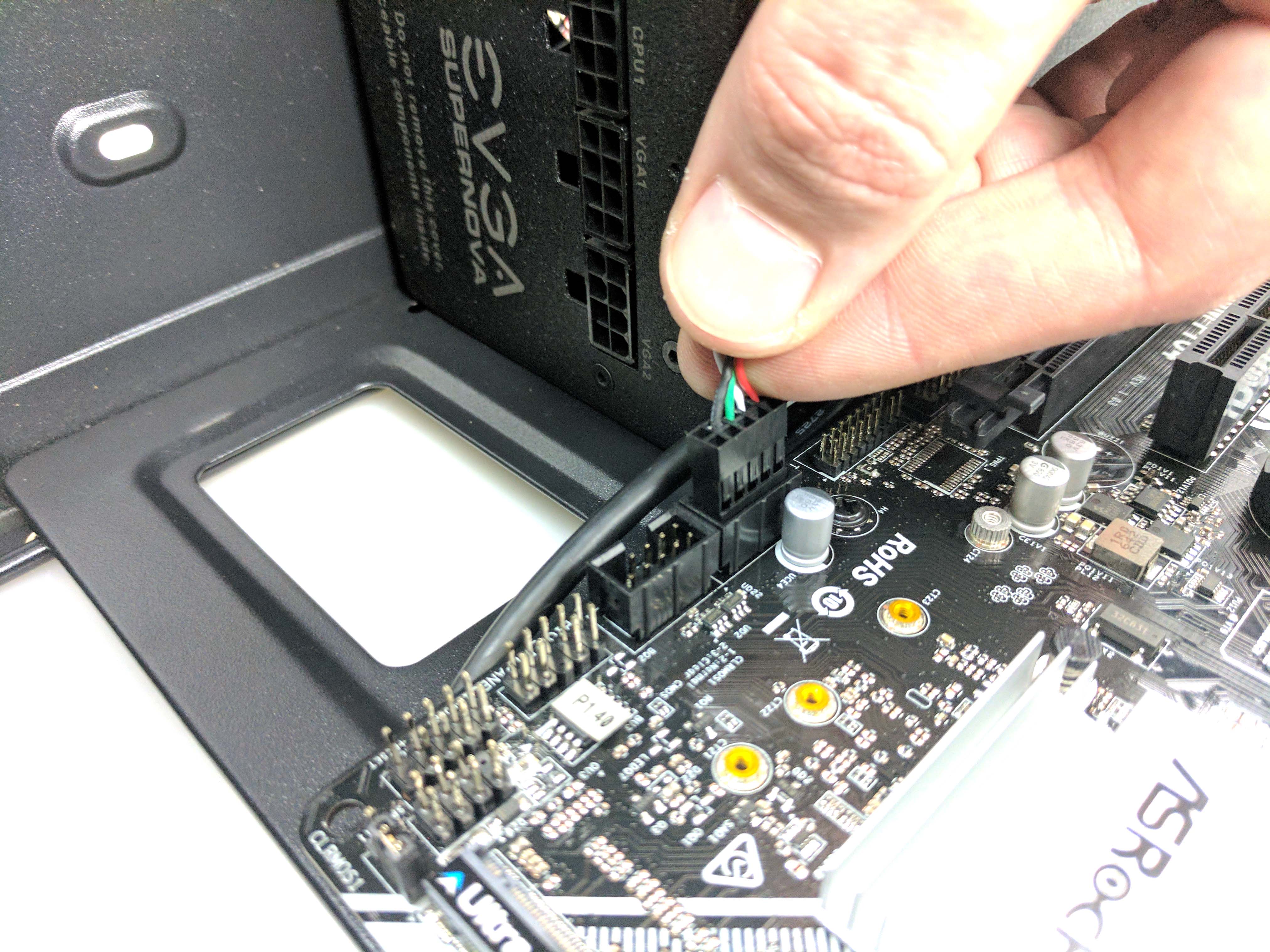
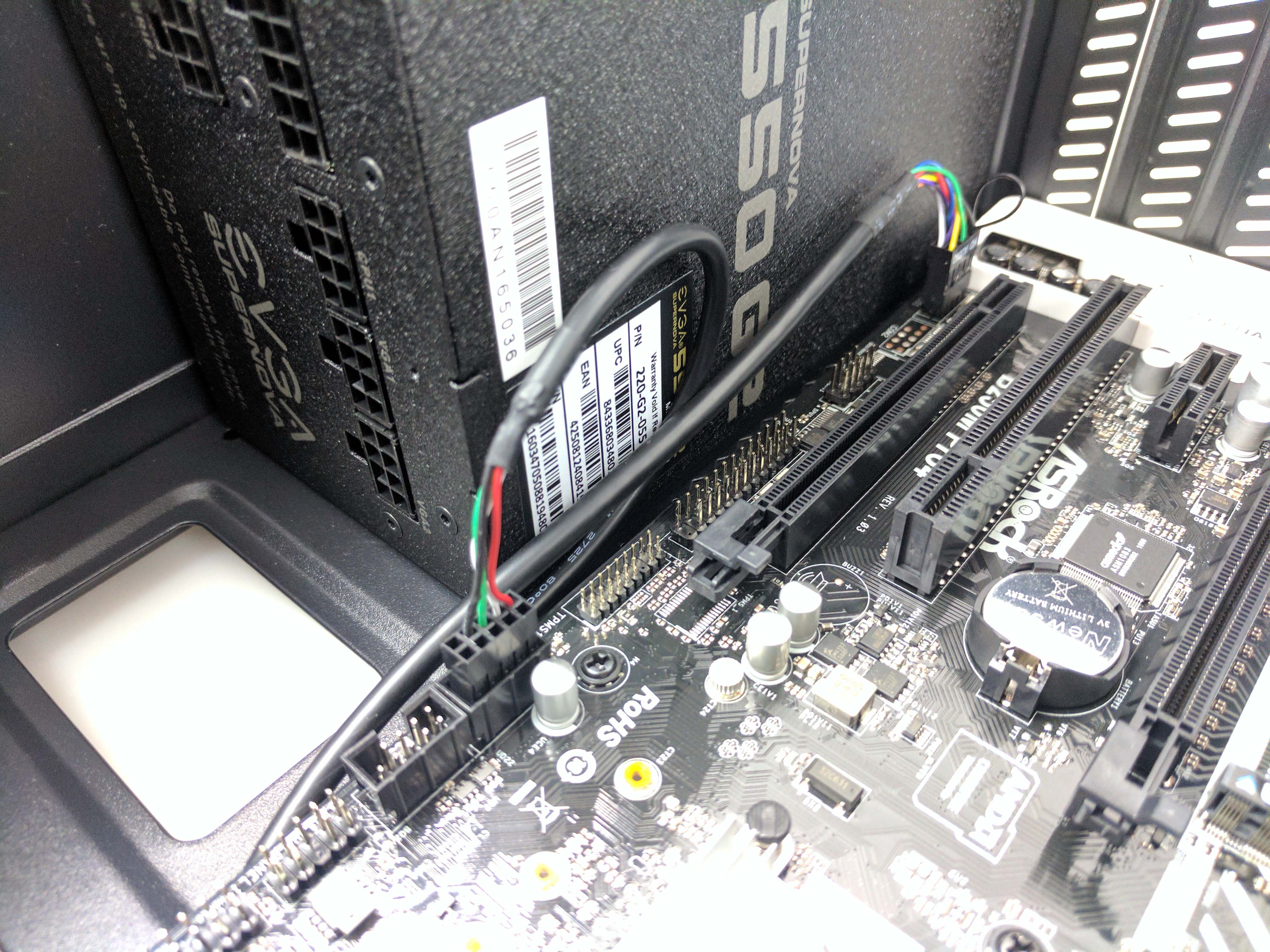
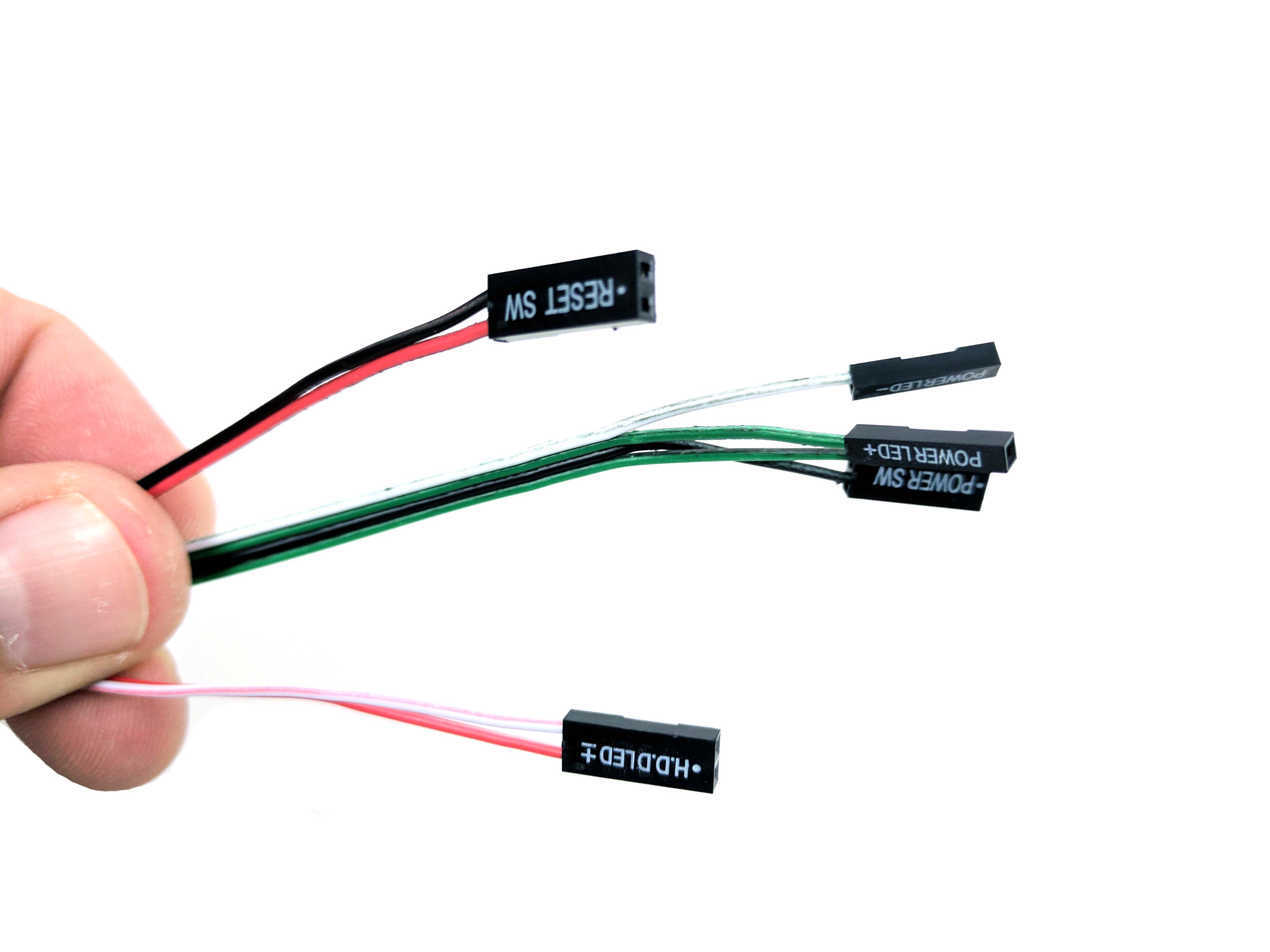
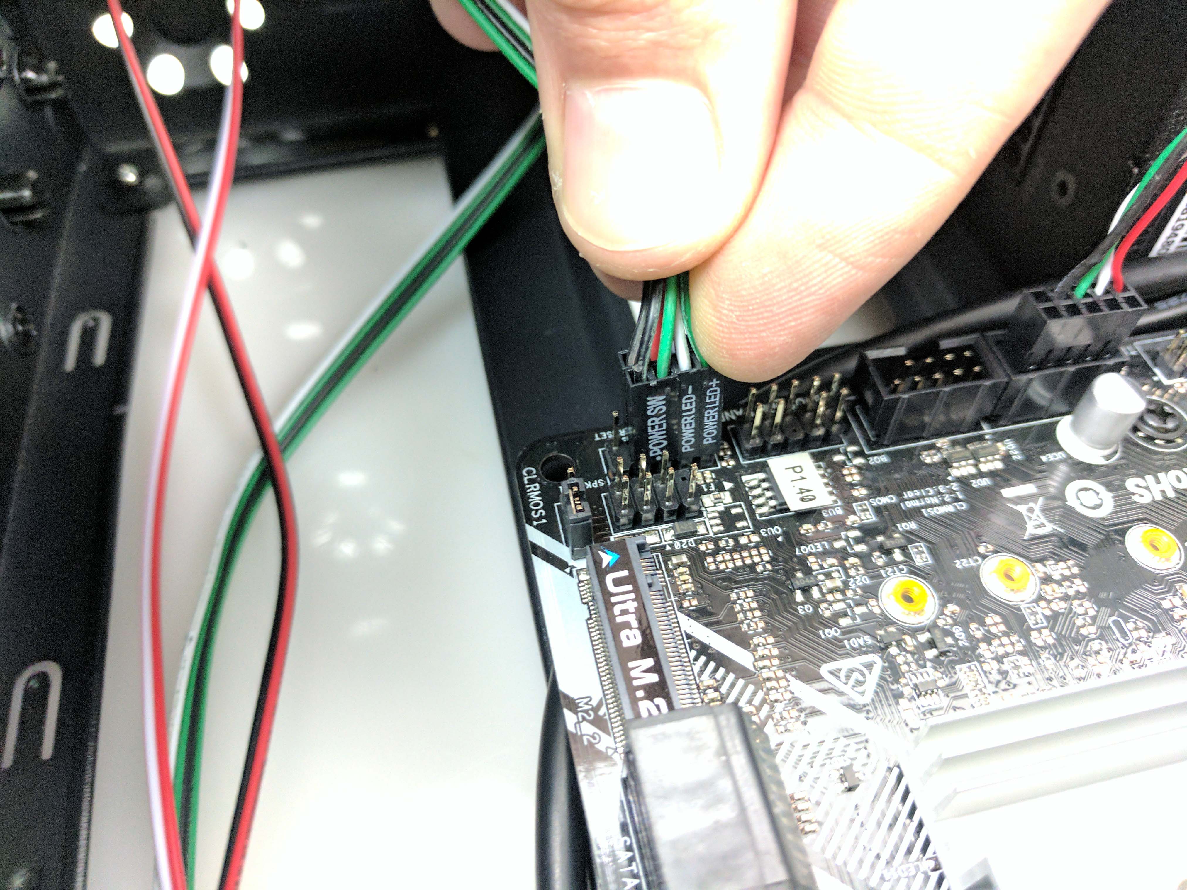
Run the front panel I/O wiring down the case and plug the leads into the appropriate pins (it's printed really small on the motherboard, or refer to your manual). Let the excess hang; there’s still not much to be done about the cable mess. Plug in the USB 3.0 cable (3rd picture below) and let the slack loop naturally into the lower part of the chassis.
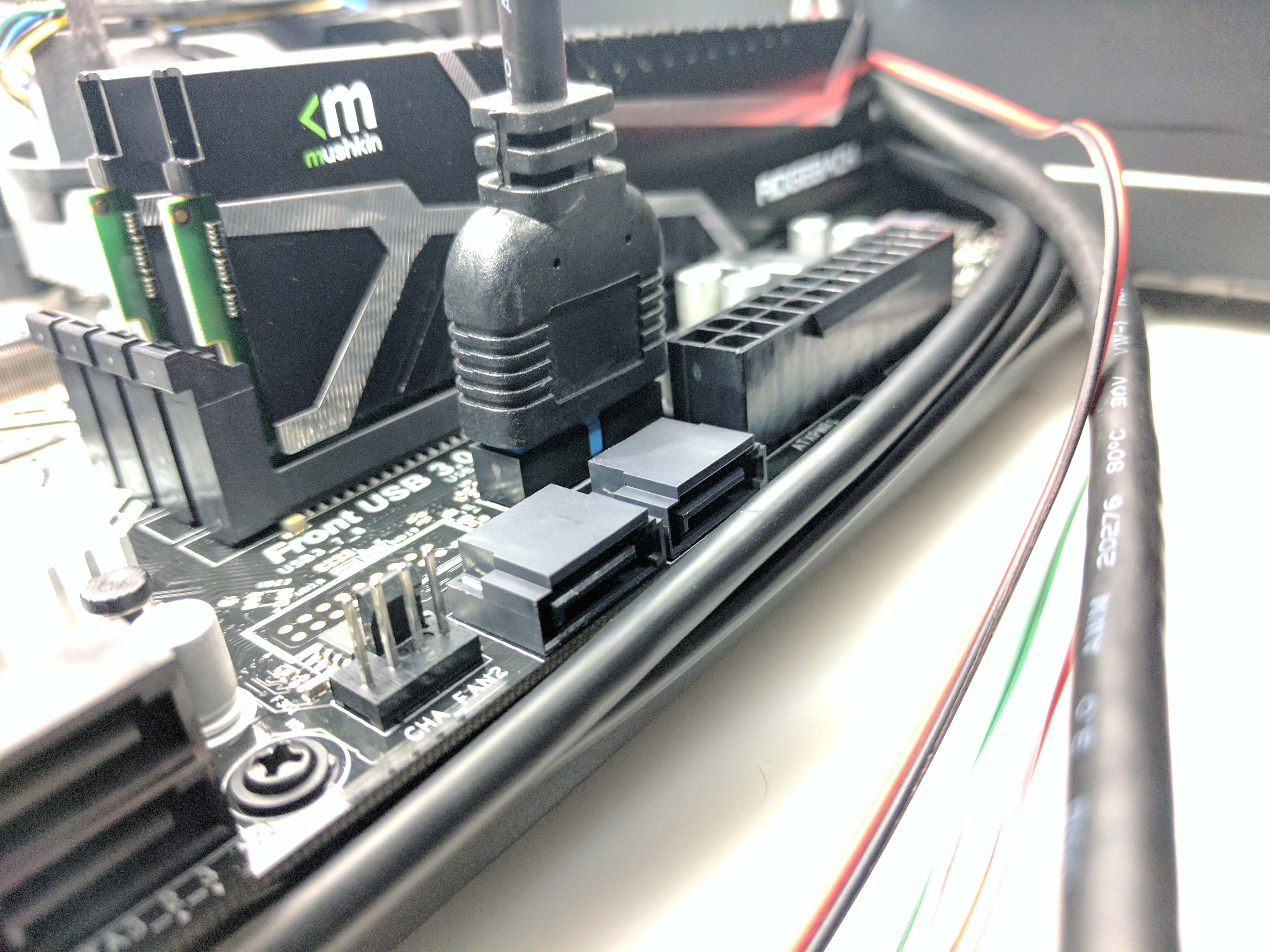
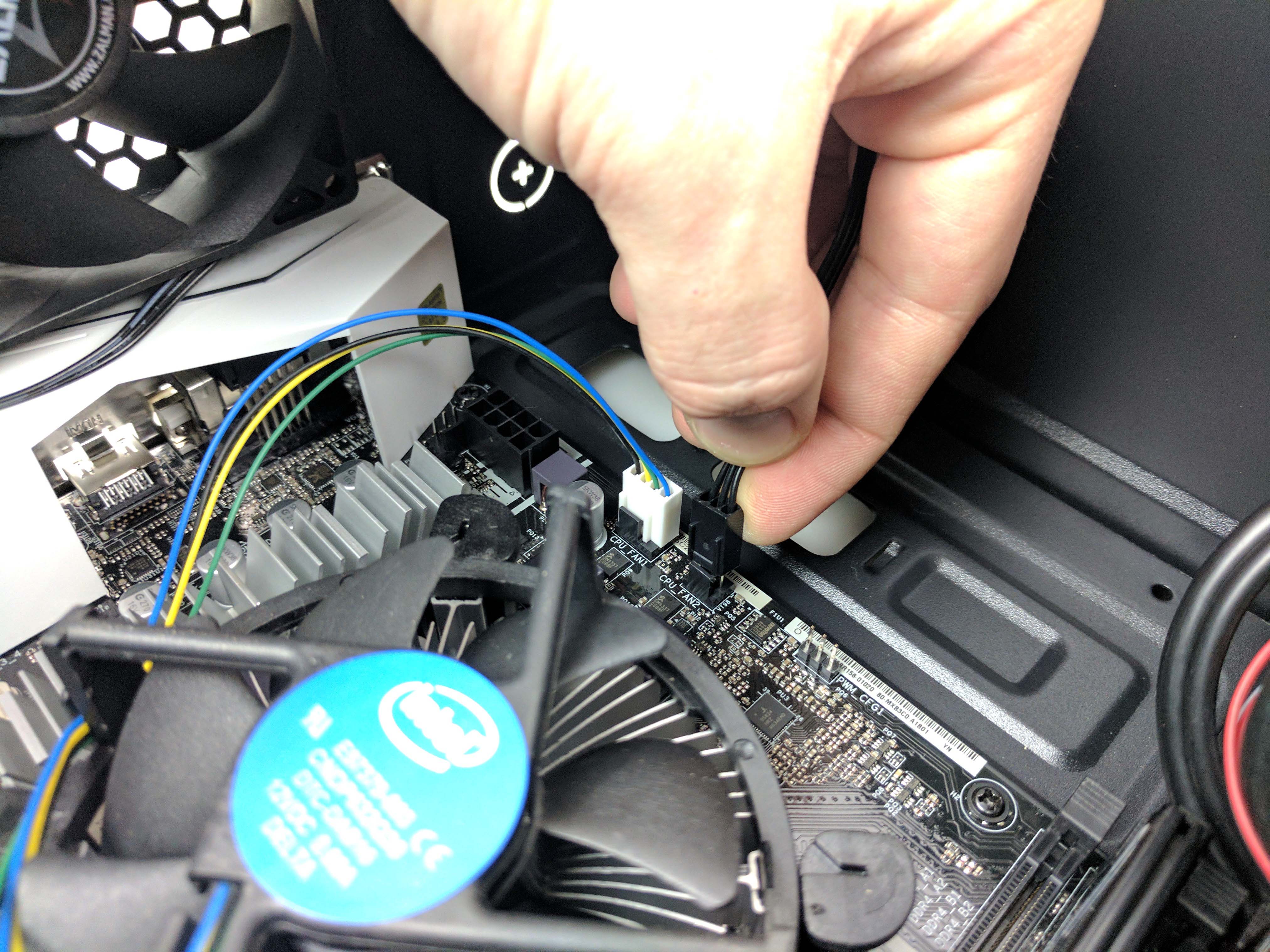
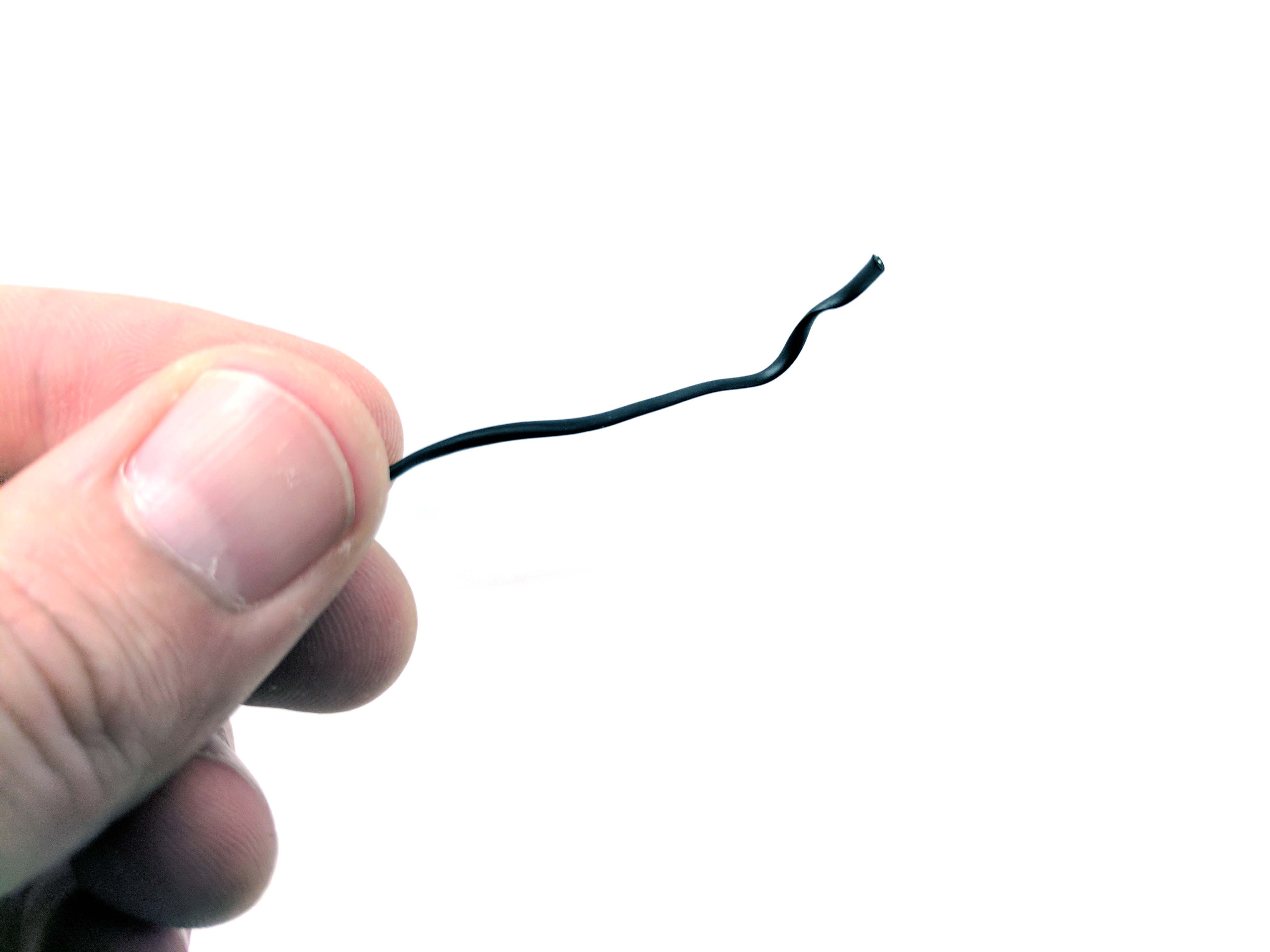
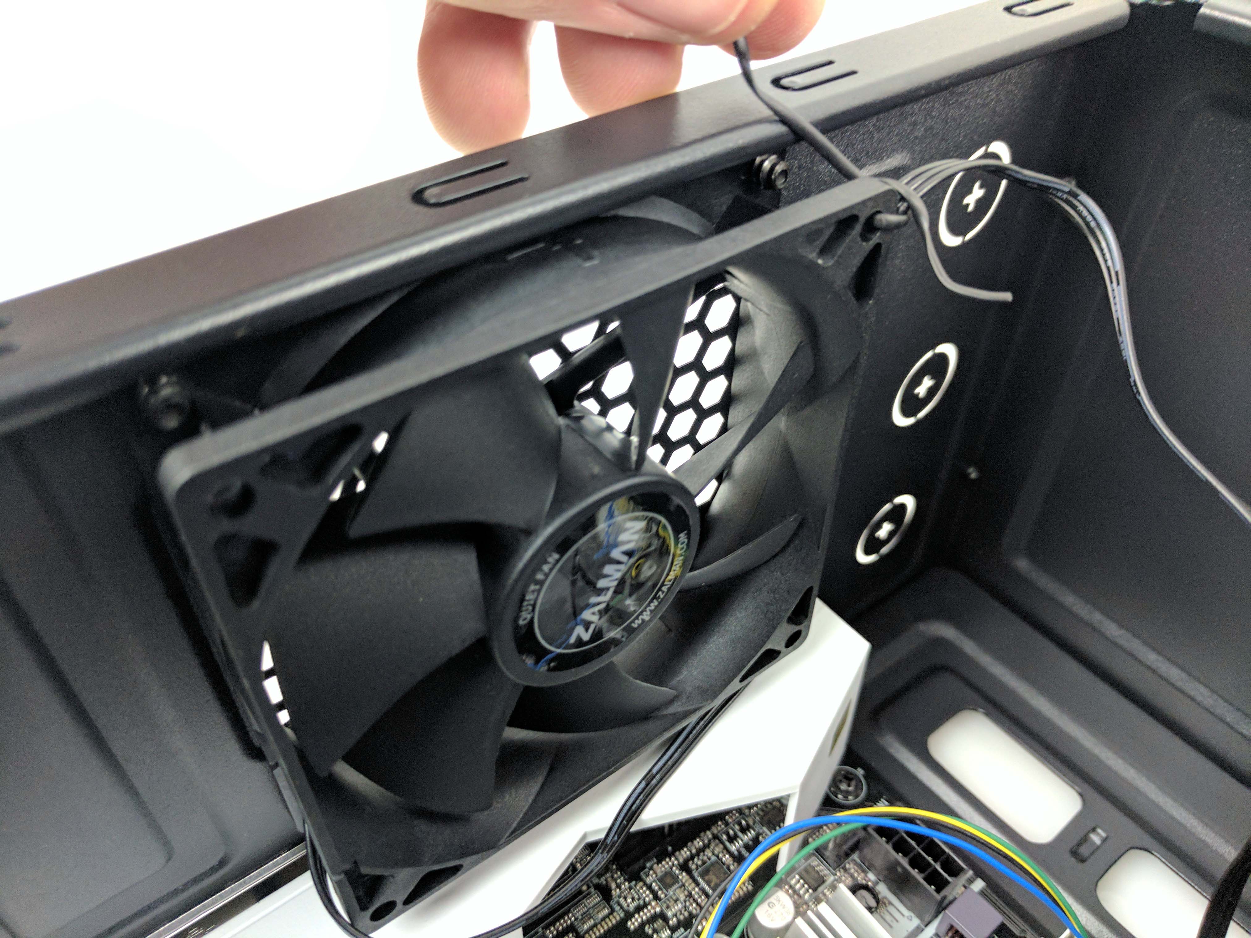
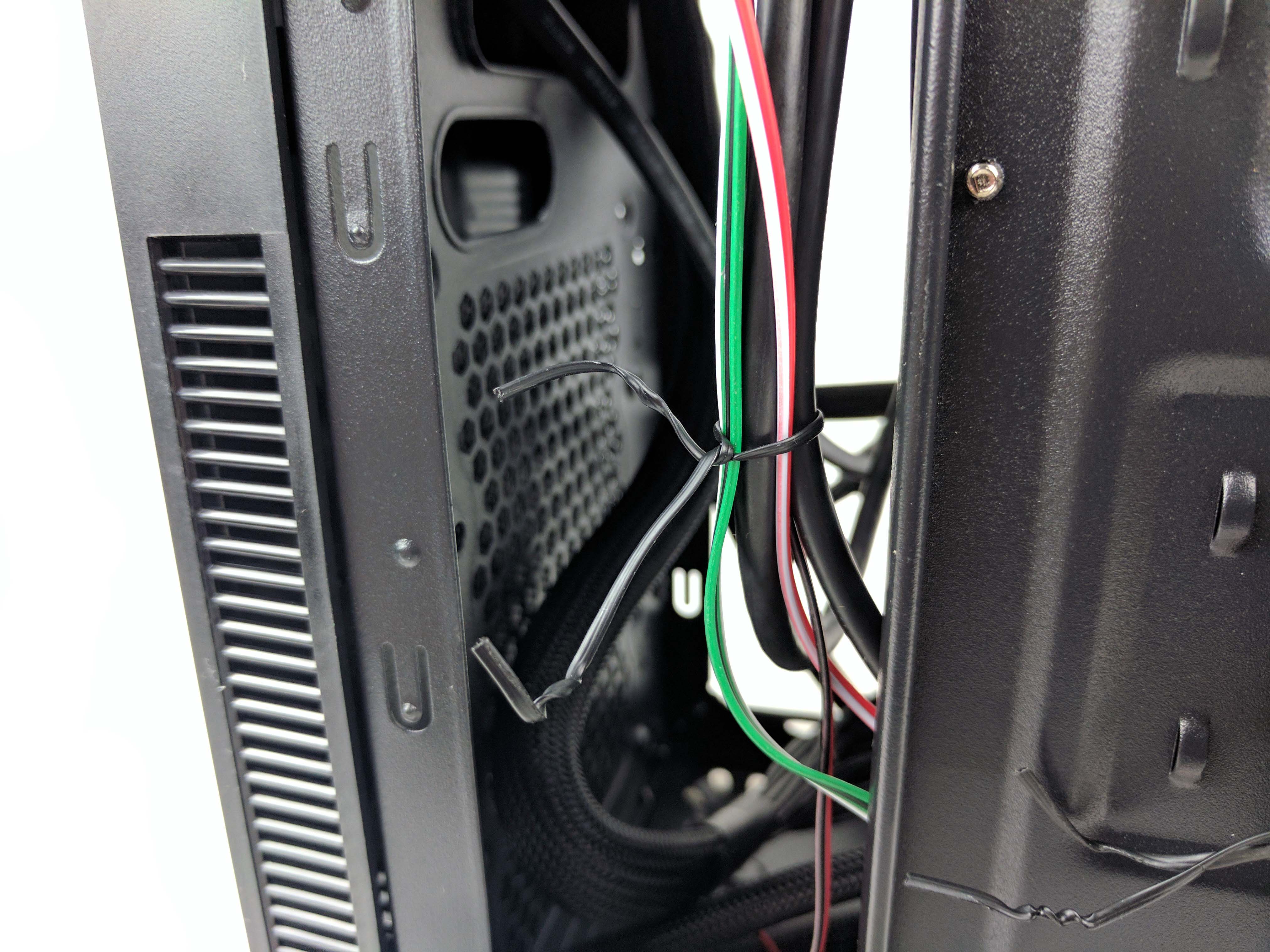
Untie the rear 80mm case fan cable and connect it to the CPU FAN 2 port on the motherboard. You can use a tie wrap through one of the fan’s mounting holes to secure the wire under the fan and up the side to reduce the slack (as seen in the last picture above).
The SSD
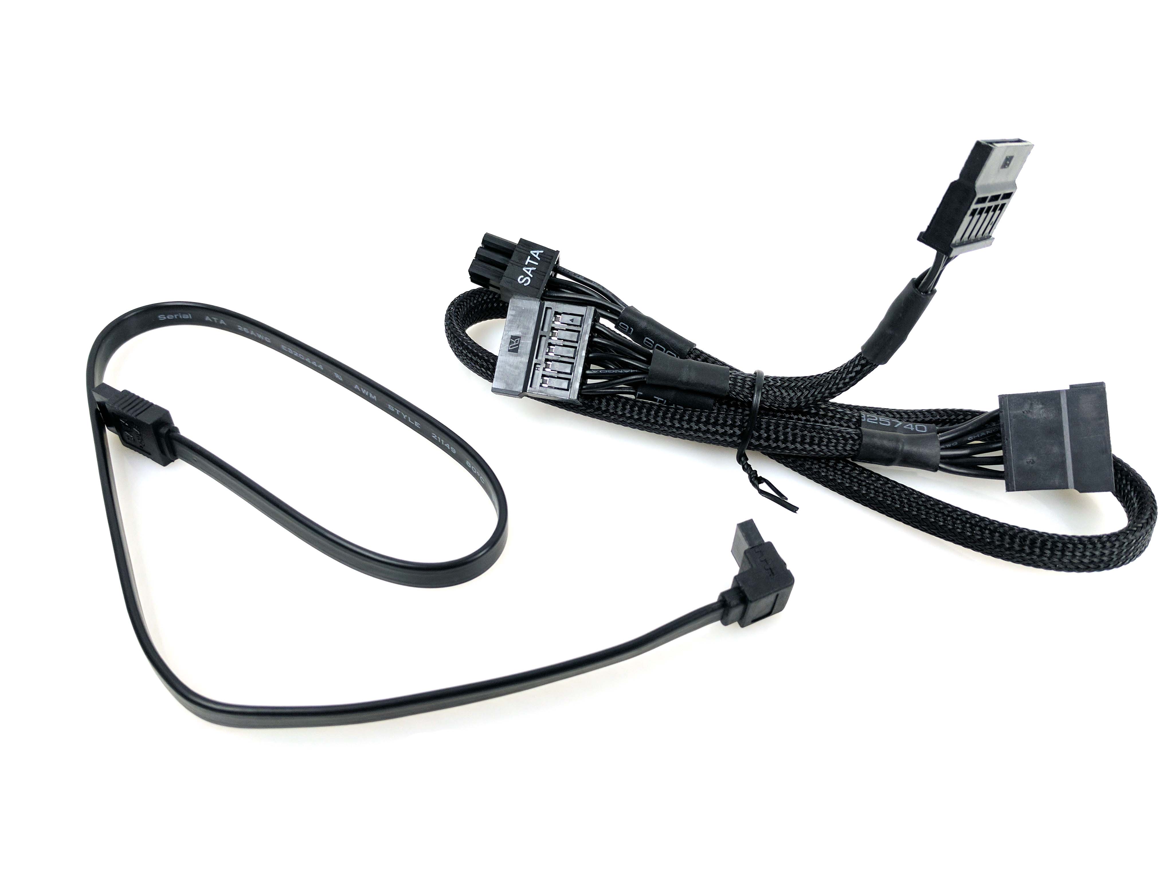
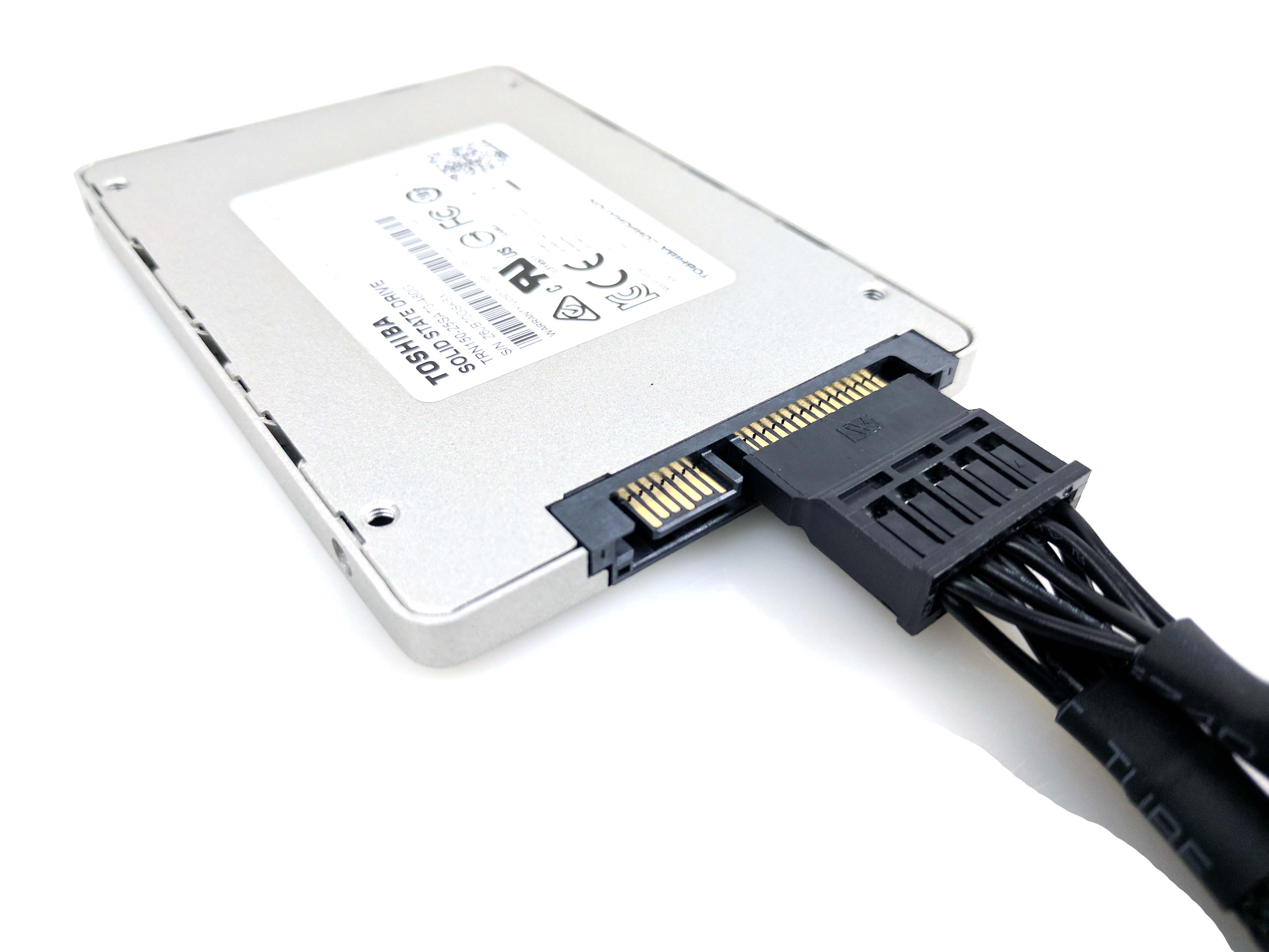
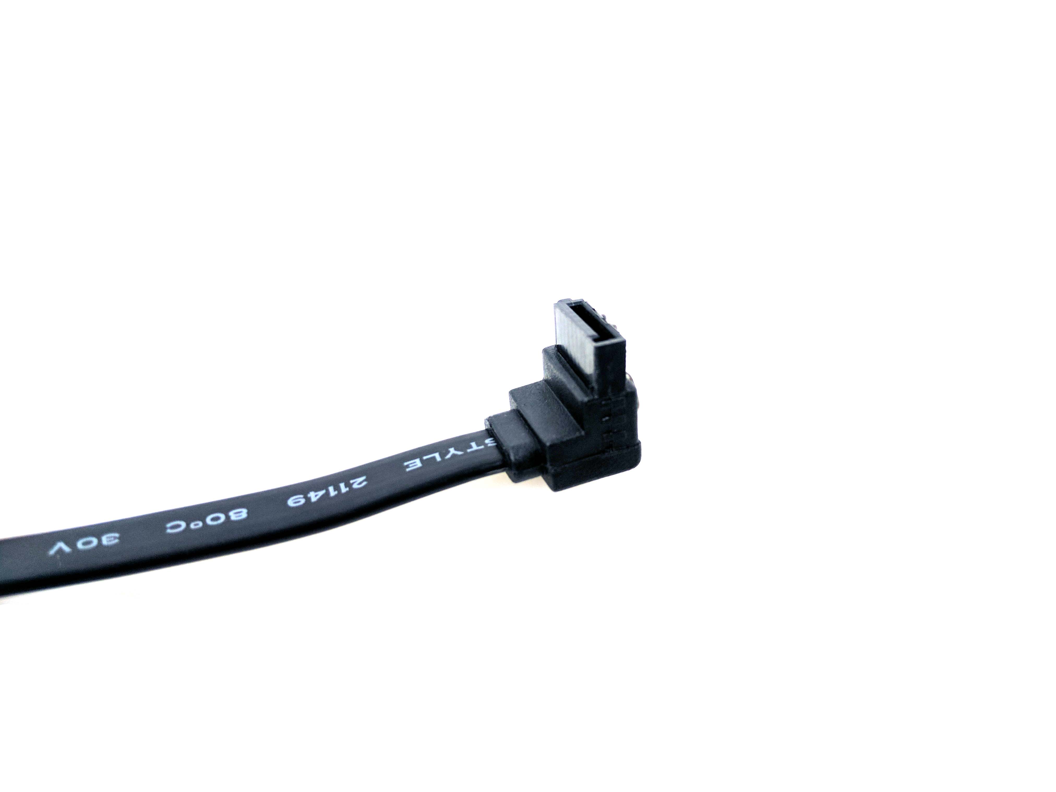
Remove the 480GB OCZ Trion 150 SSD from its packaging. Thanks to the modularity of the PSU, we can plug in the cables before mounting it to the case. Grab a SATA power cable from the PSU box, in addition to the angled SATA data cable (see slide 2 below). Plug in the SATA power cable using the very last plug on the line, then connect the SATA data cable with the angled plug attached to the SSD.
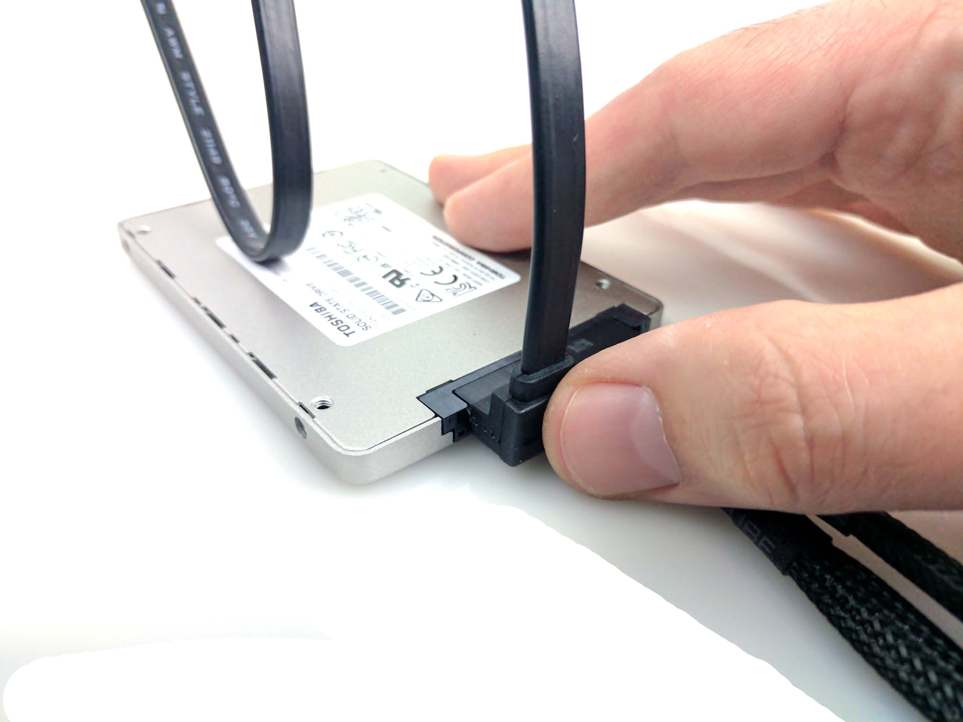
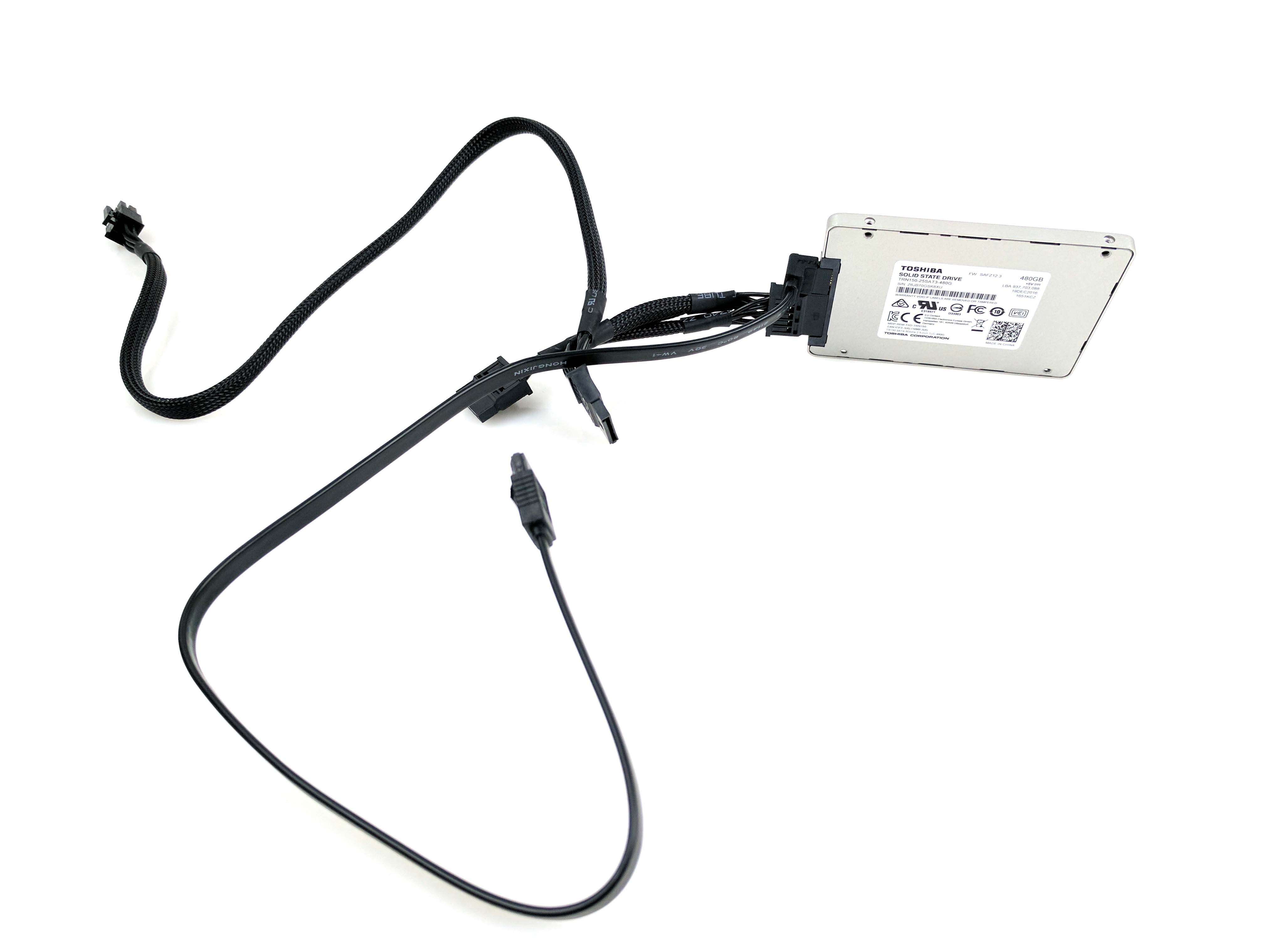
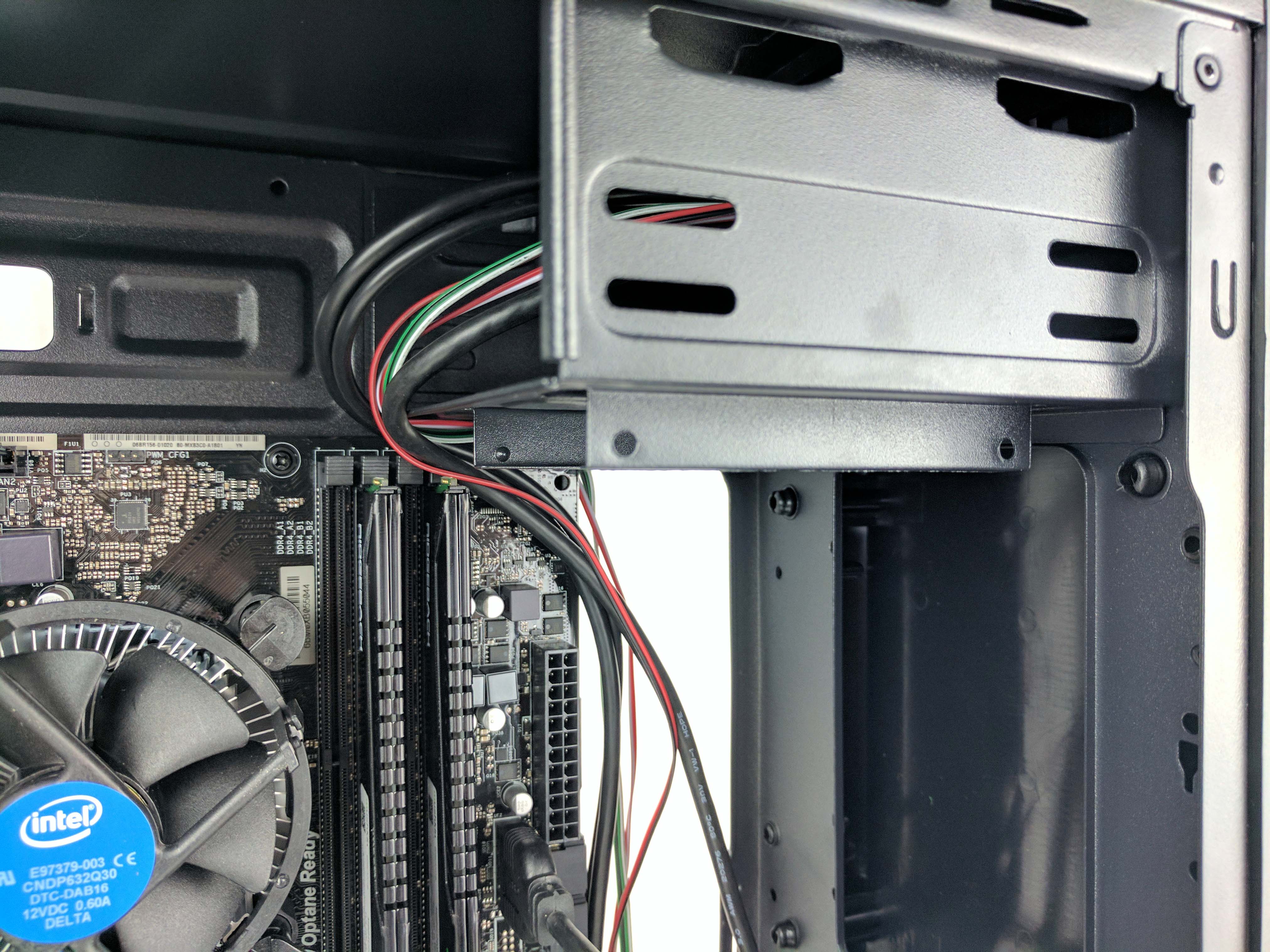
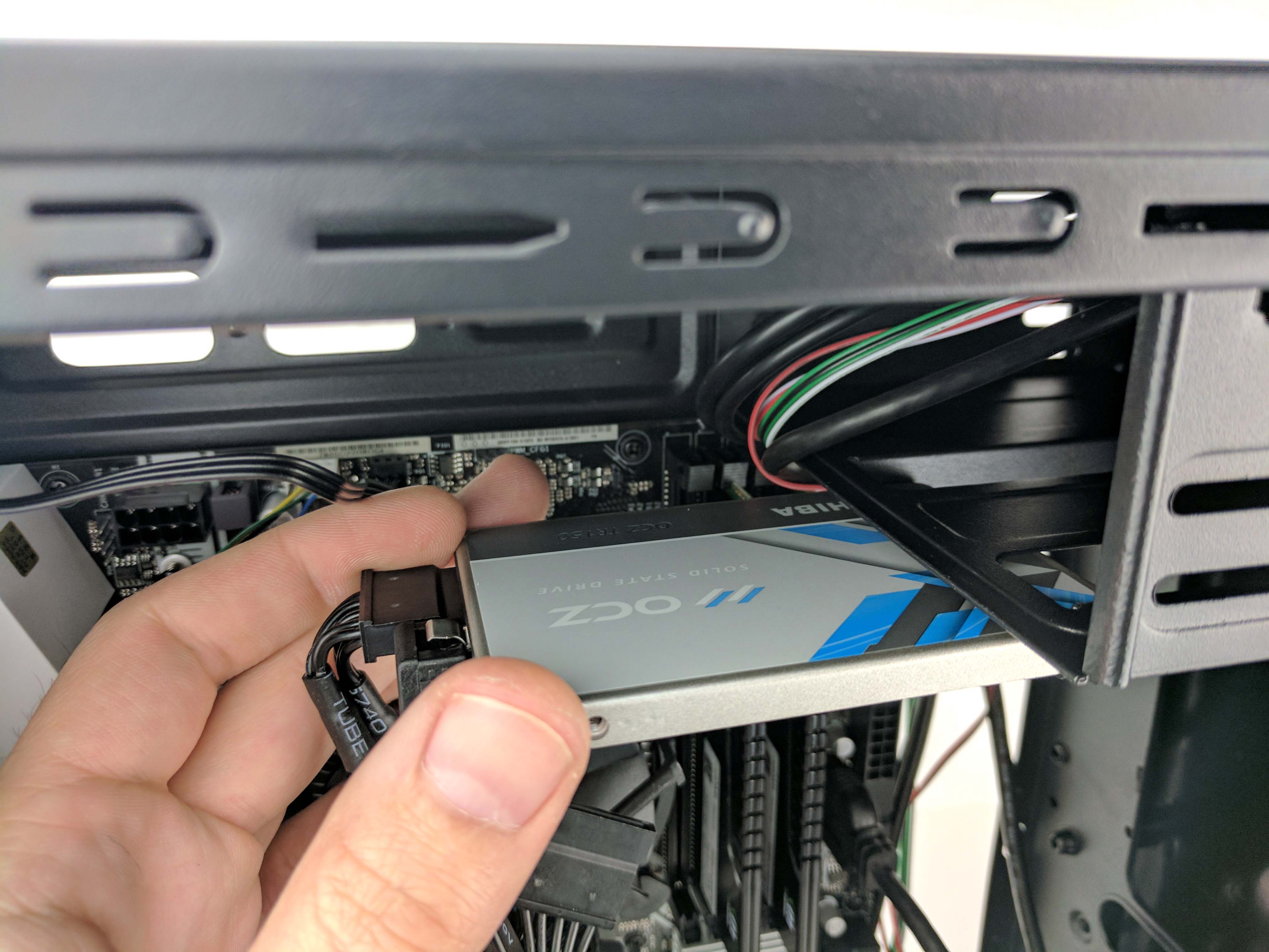
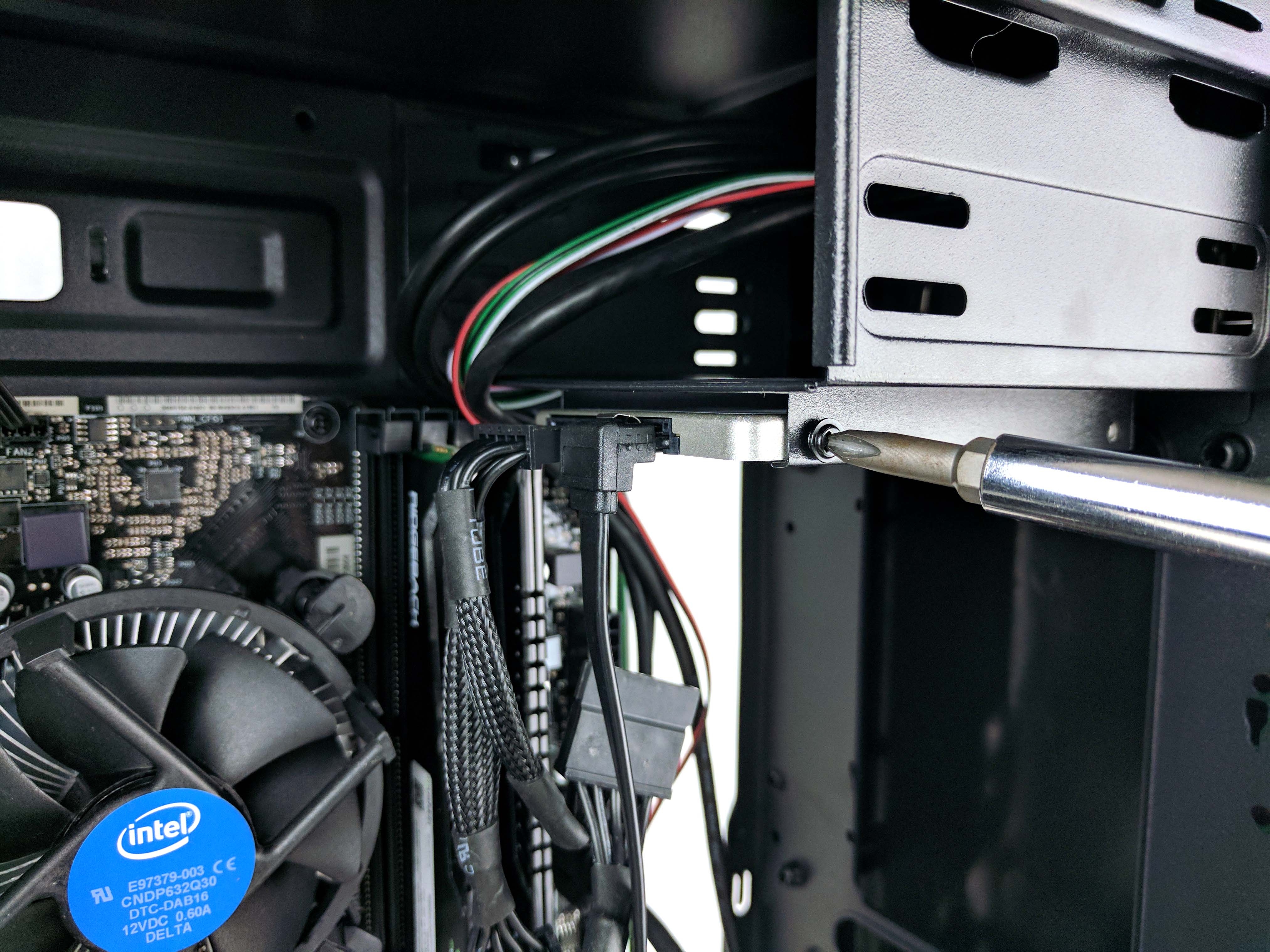
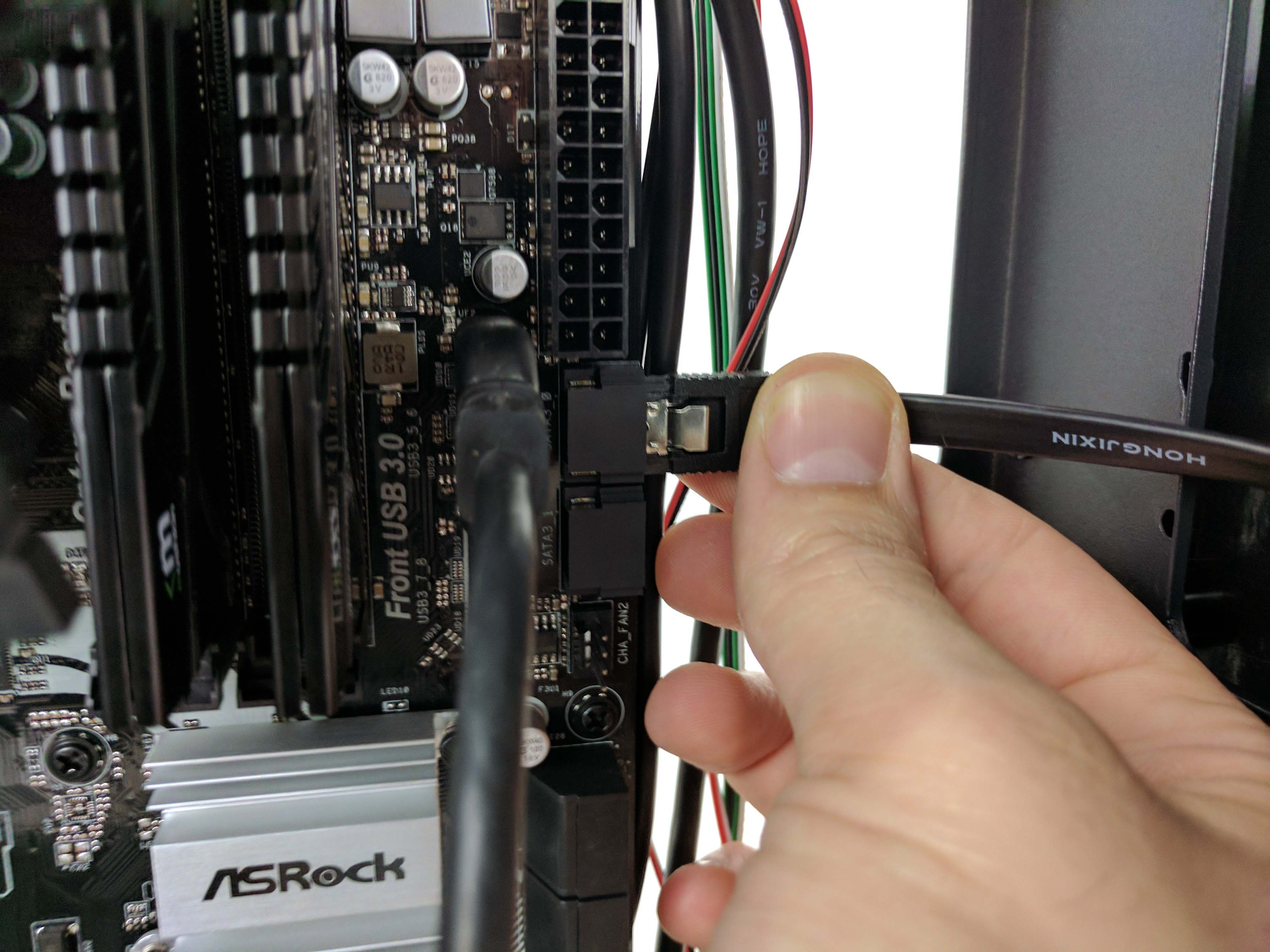
Slide the SSD into the 2.5” bay residing below the 5.25” bay at the top of the case (the 7th picture above). There are two notches in the small hanging bay that hold the left side of the SSD in place, and you may need to convince the SSD to sit properly in the slot. Once you get the SSD over the hump, line up the visible (right) side with the case’s screw holes and secure the drive to the case with two of the thin-threaded, rimmed screws. Plug in the SATA data cable to the SATA_3 0 port on the motherboard (right next to the ATX power plug, as seen in the last picture in the album above) and loop the excess into the cable jungle. Let the SATA power plug hang for now.
The Graphics Card
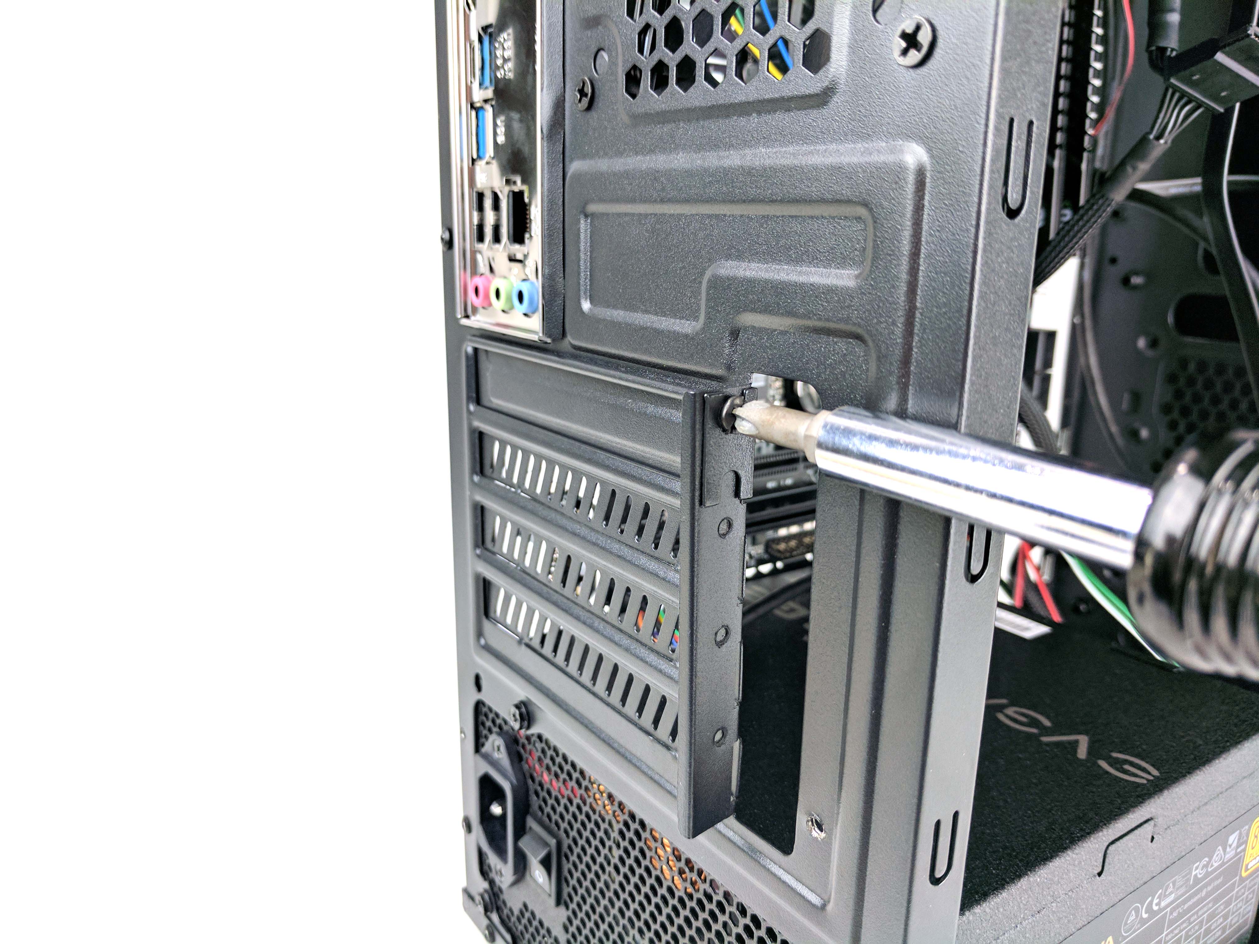
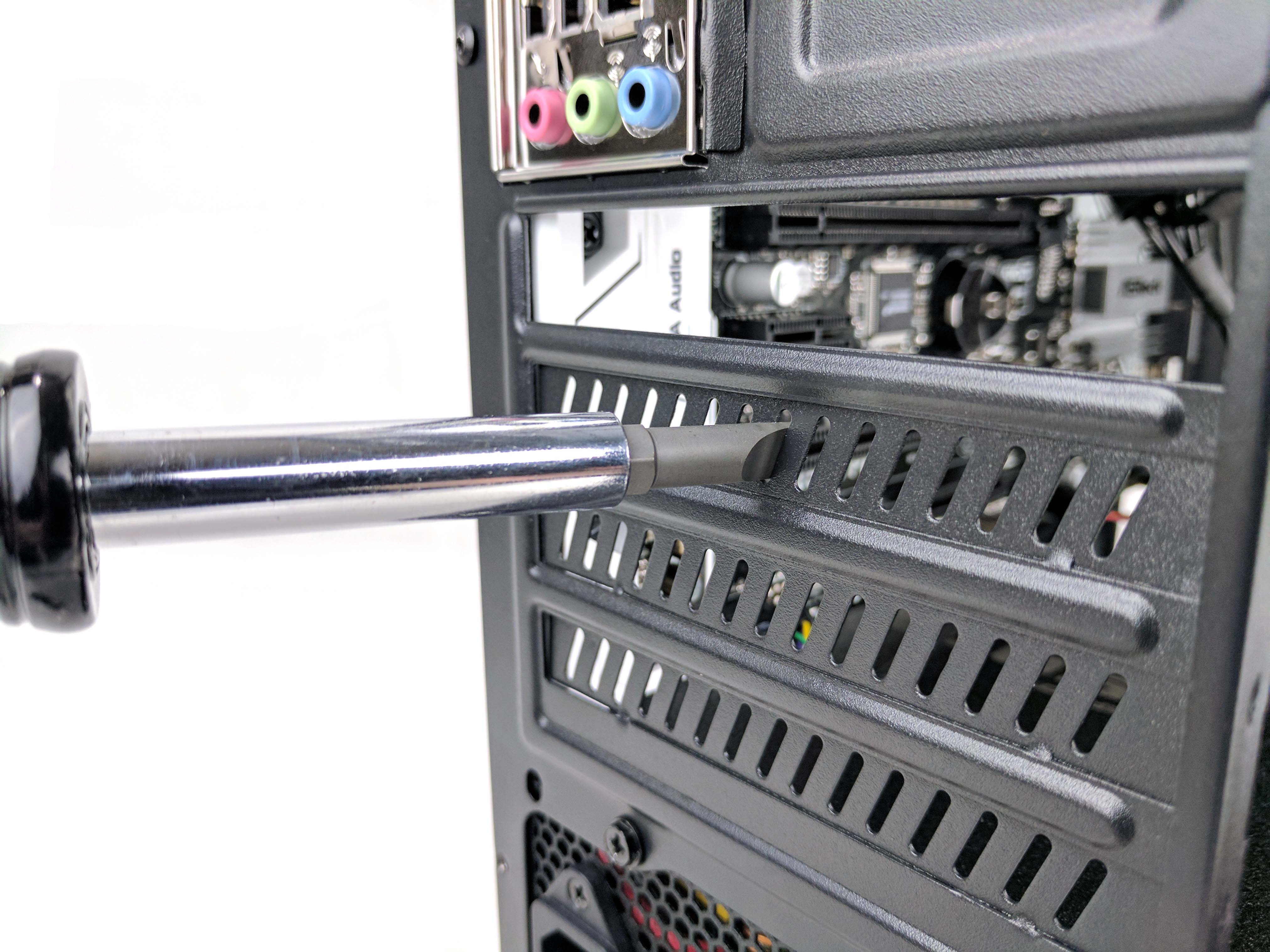
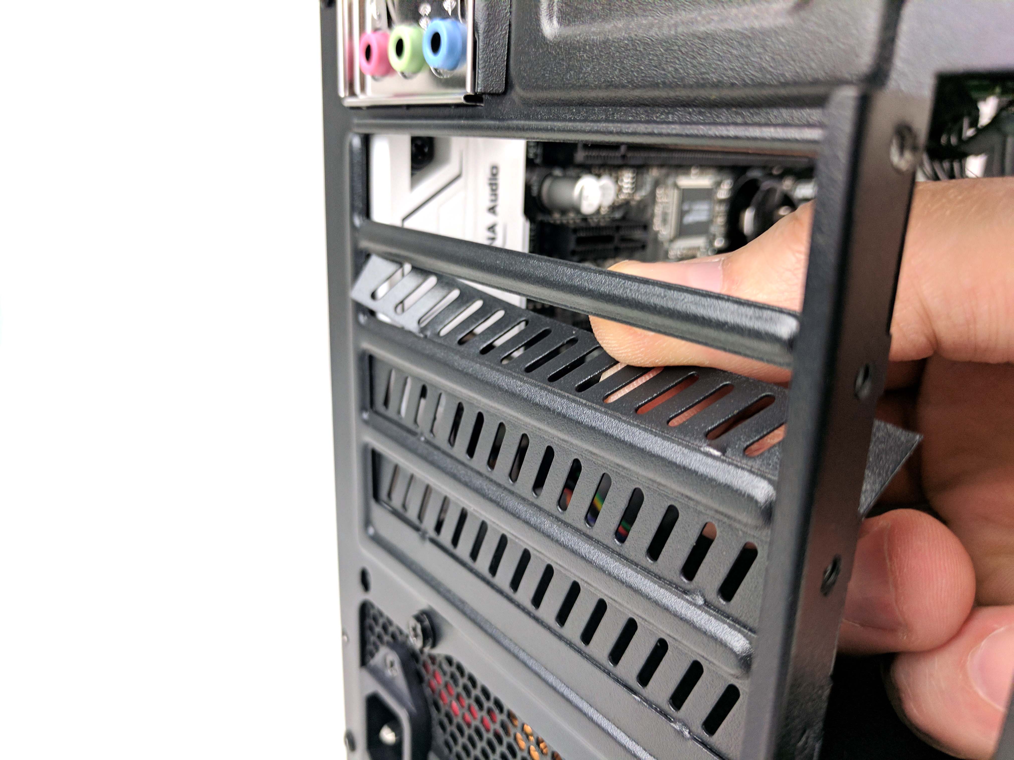
To install the graphics card, we’ll have to first remove the PCIe lane plates on the rear of the case. Remove the two screws that secure the angled plate and set it aside. Unscrew the first PCIe lane plate and use a flathead screwdriver to wrench the second plate from the chassis (see 4th picture below).
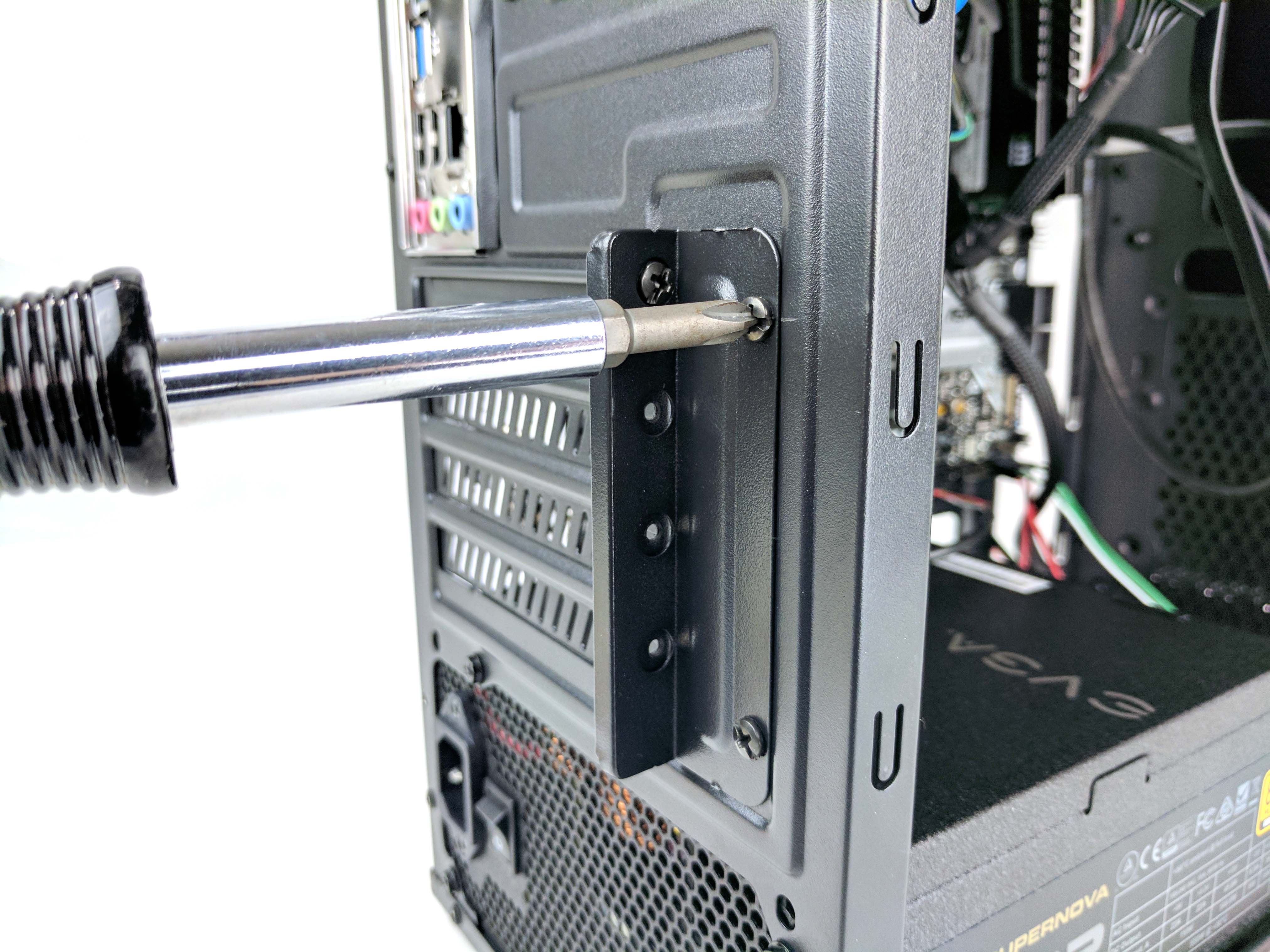
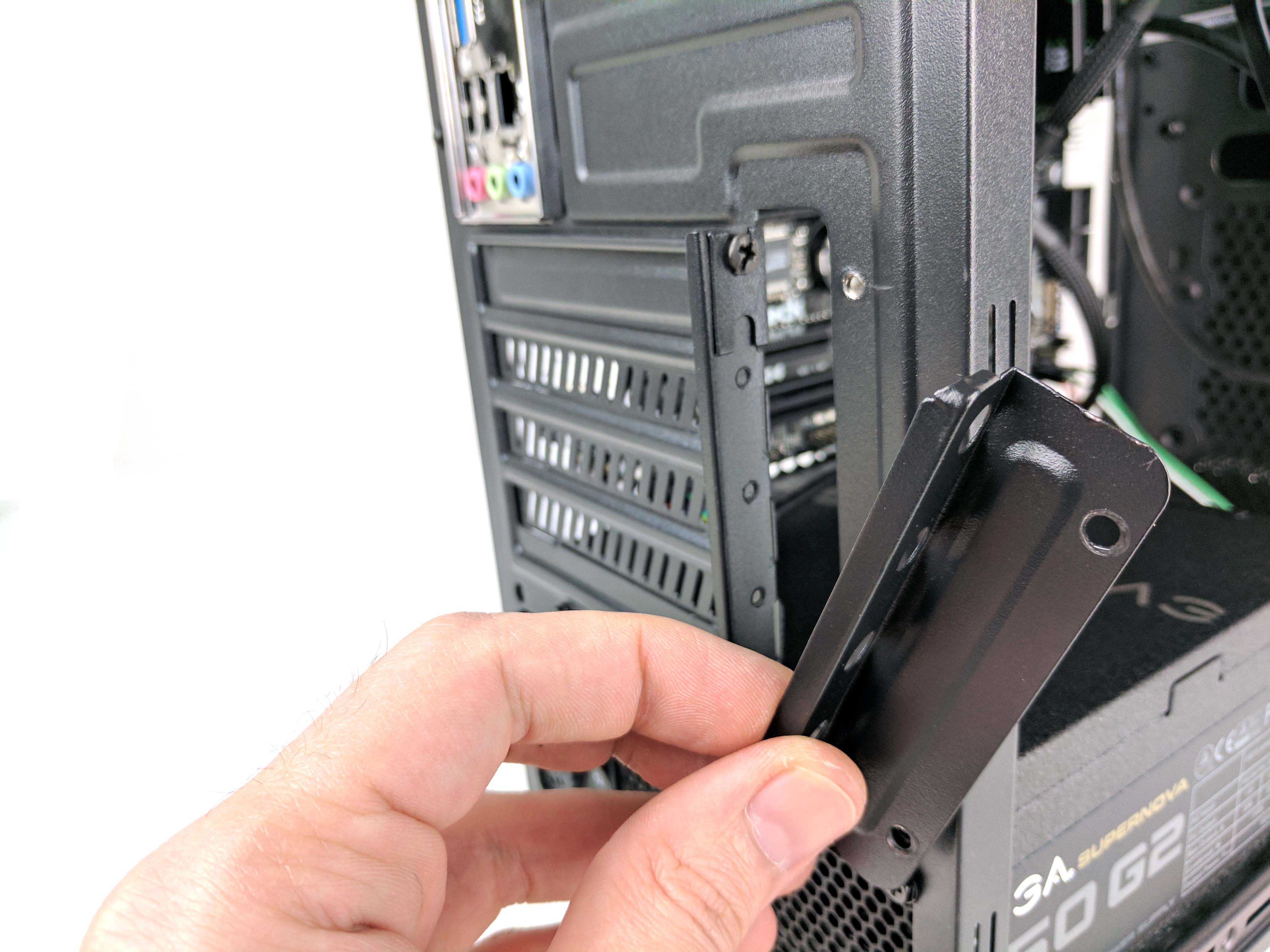
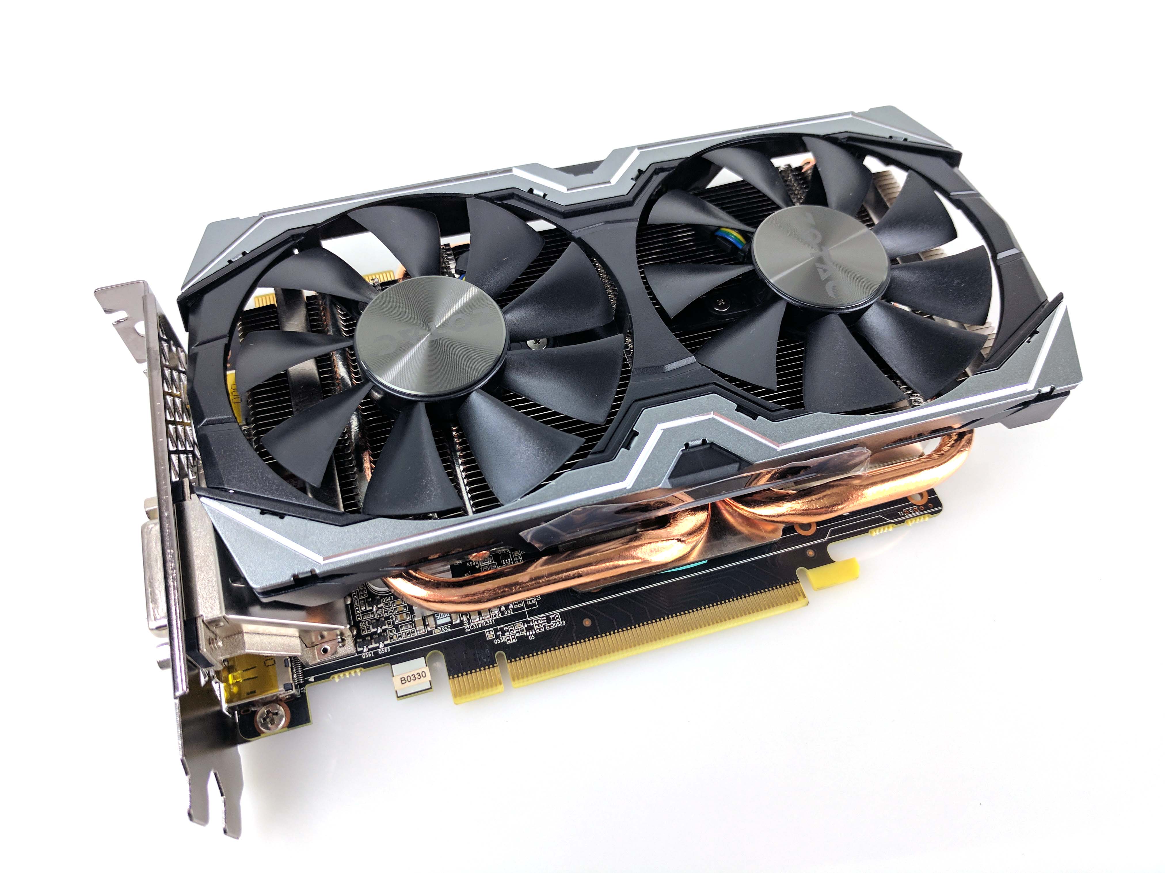
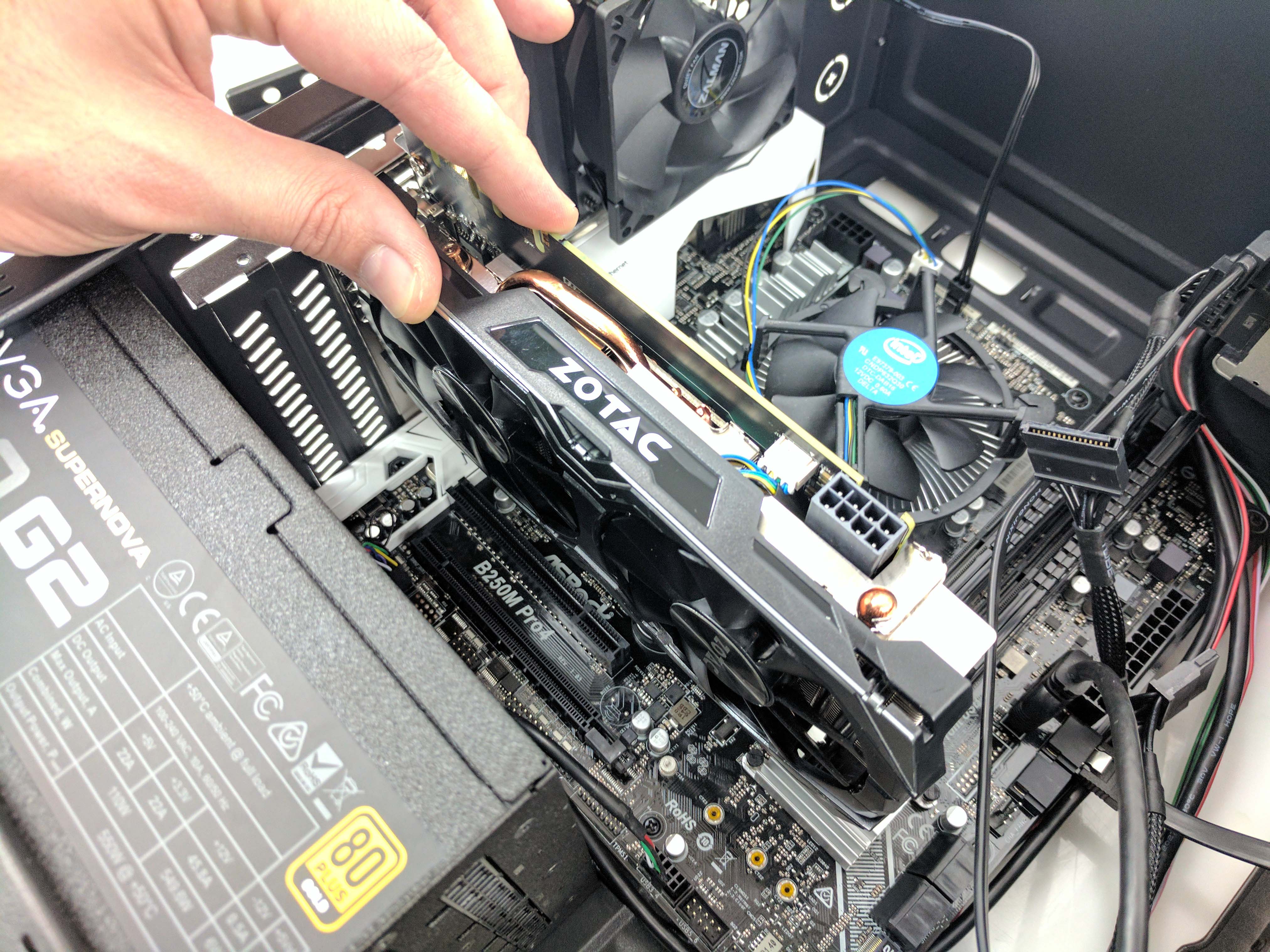
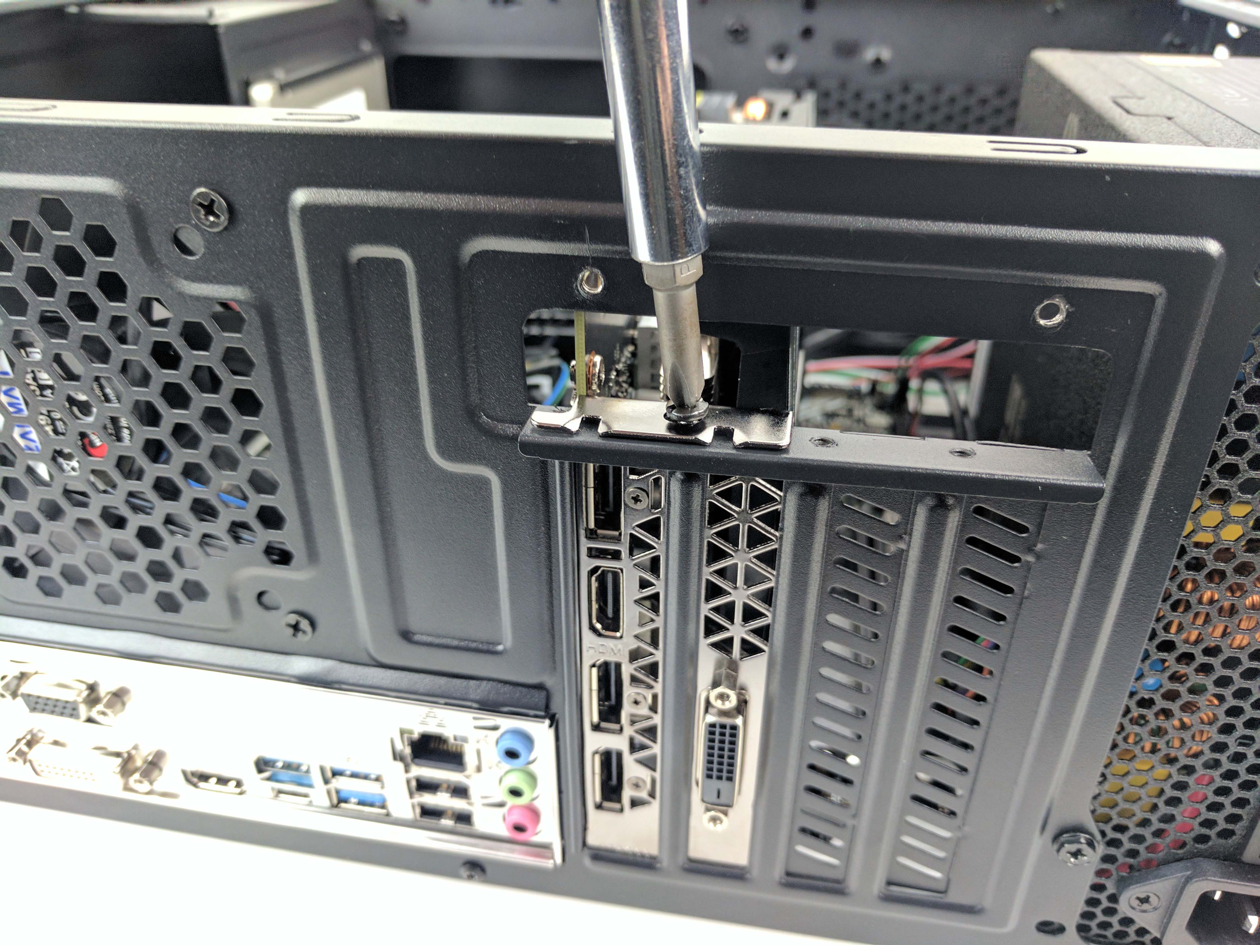
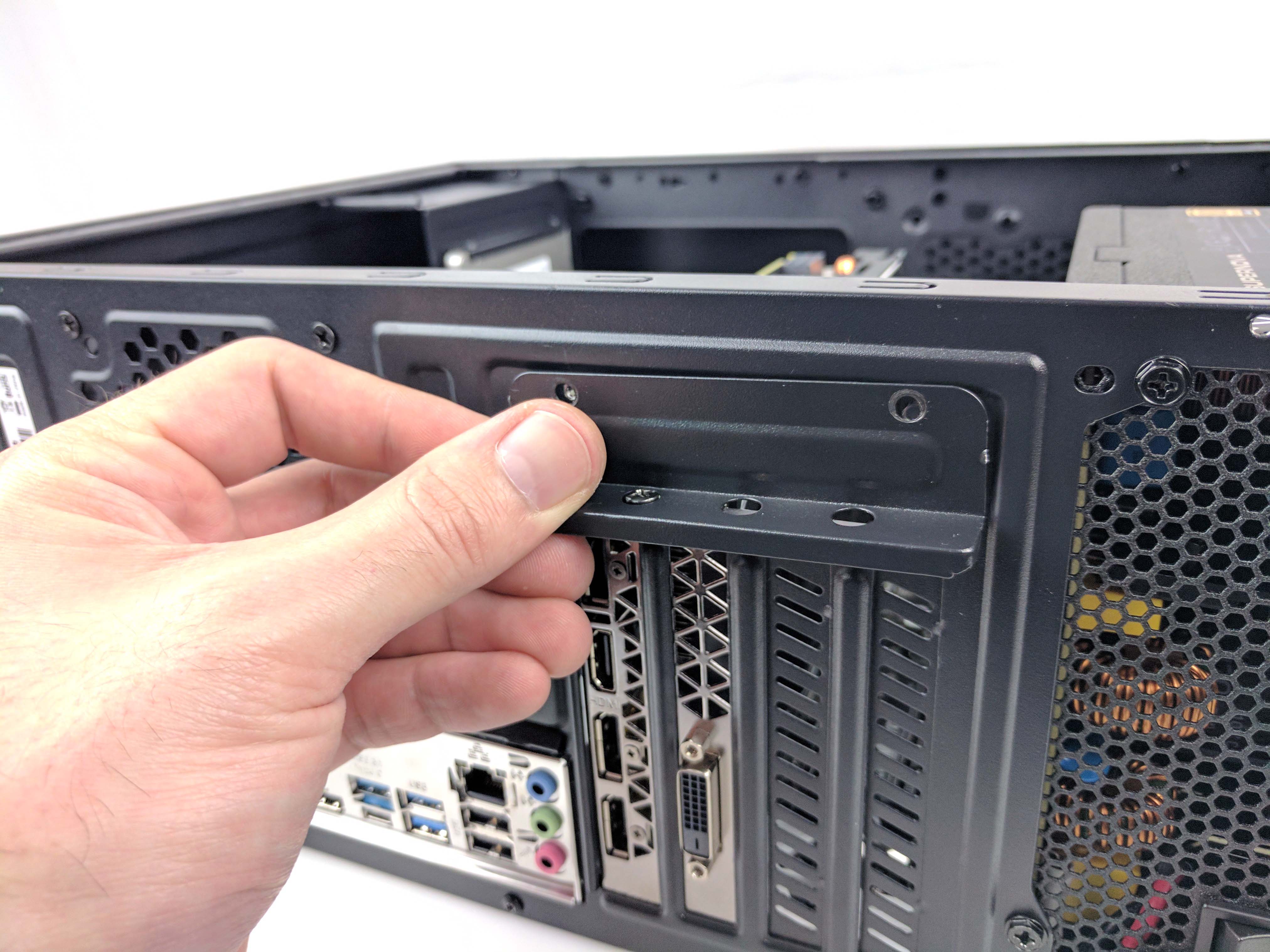
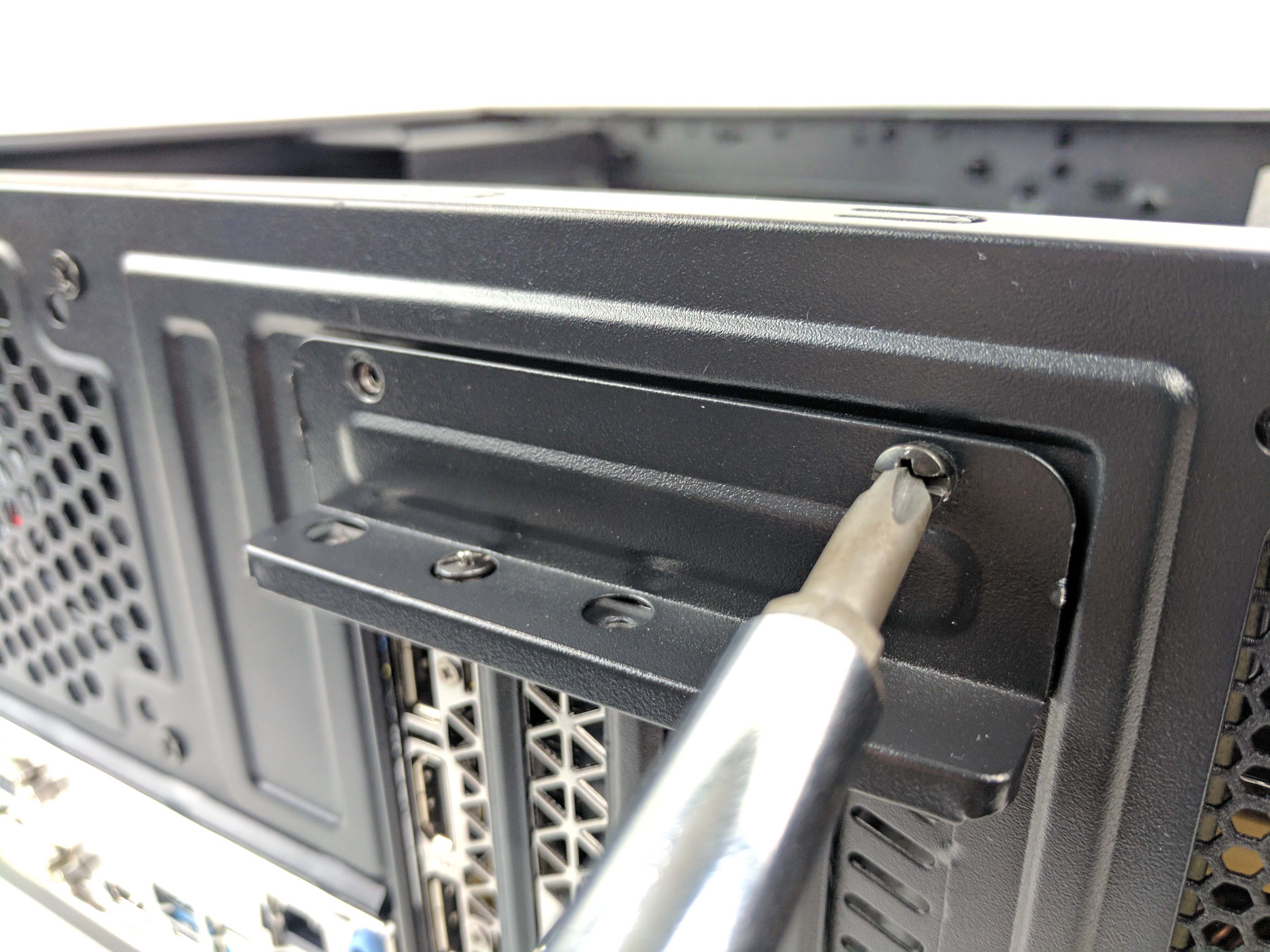
Remove the Zotac GeForce GTX 1070 Mini from its box and lower it into the chassis, lining up the PCIe x16 slot and rear panel. Push down to secure the GPU to the motherboard. Replace the PCIe lane screw to secure it to the case (as seen in the 8th picture above), then replace the angled PCIe lane cover and screw it back in.
Cable Management
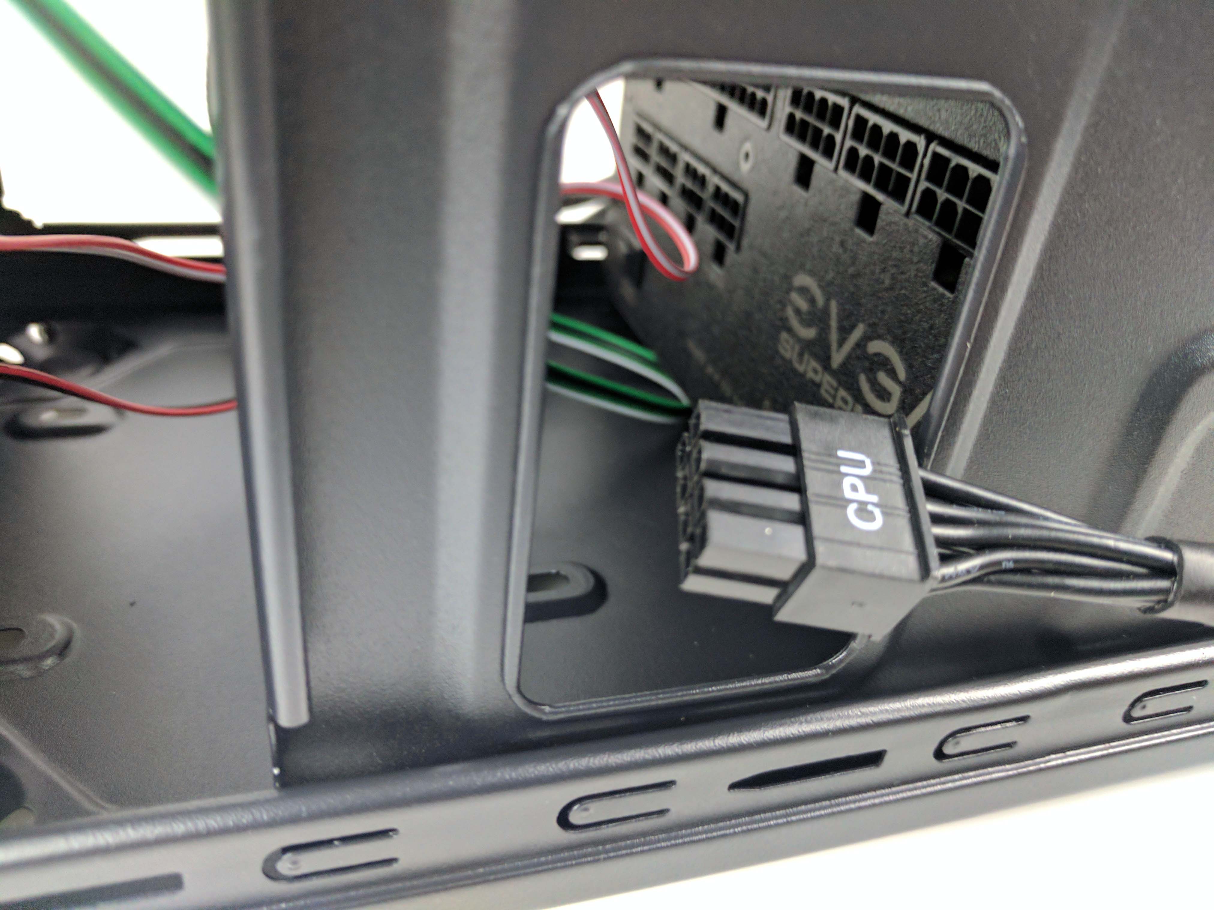
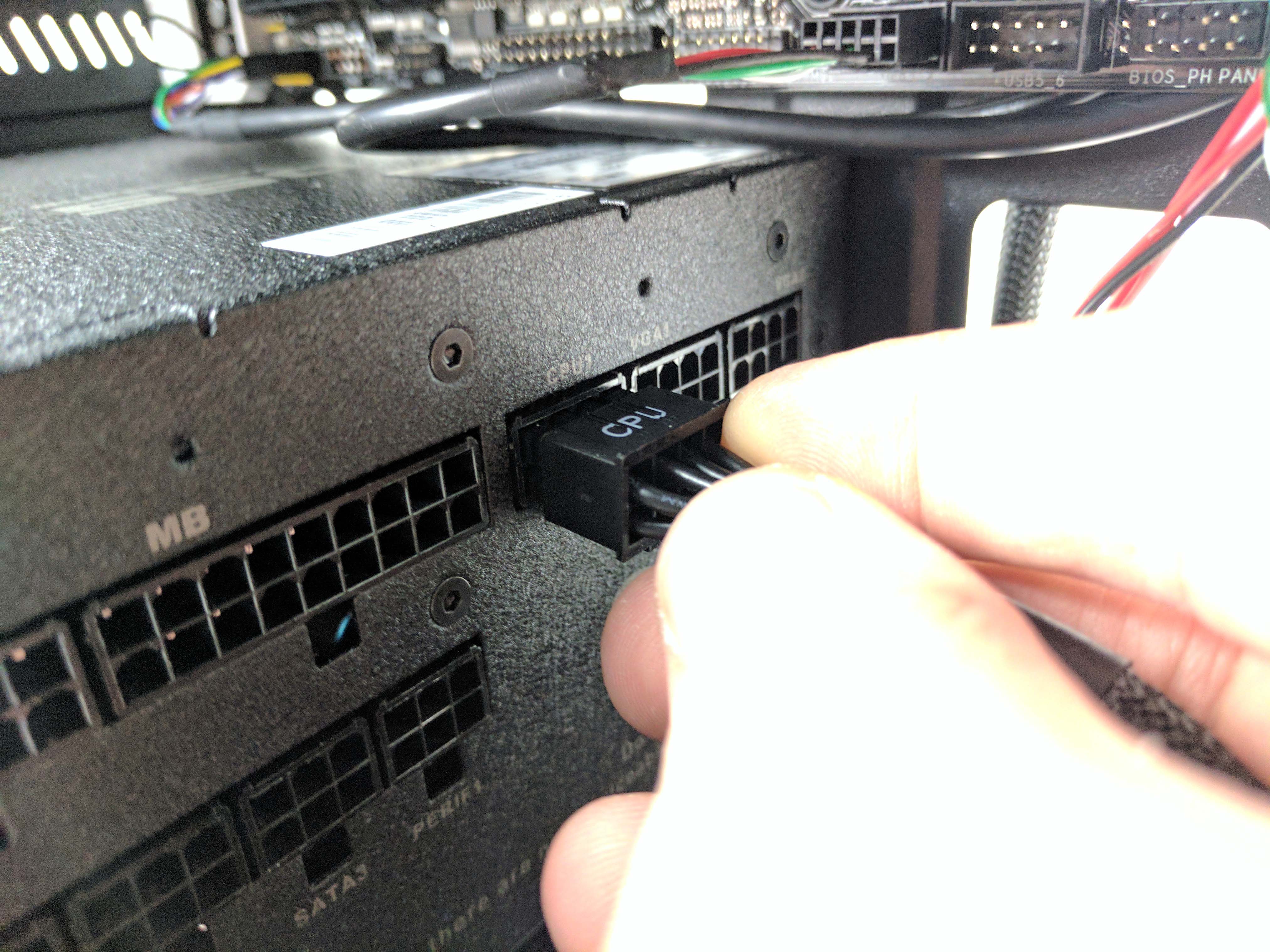
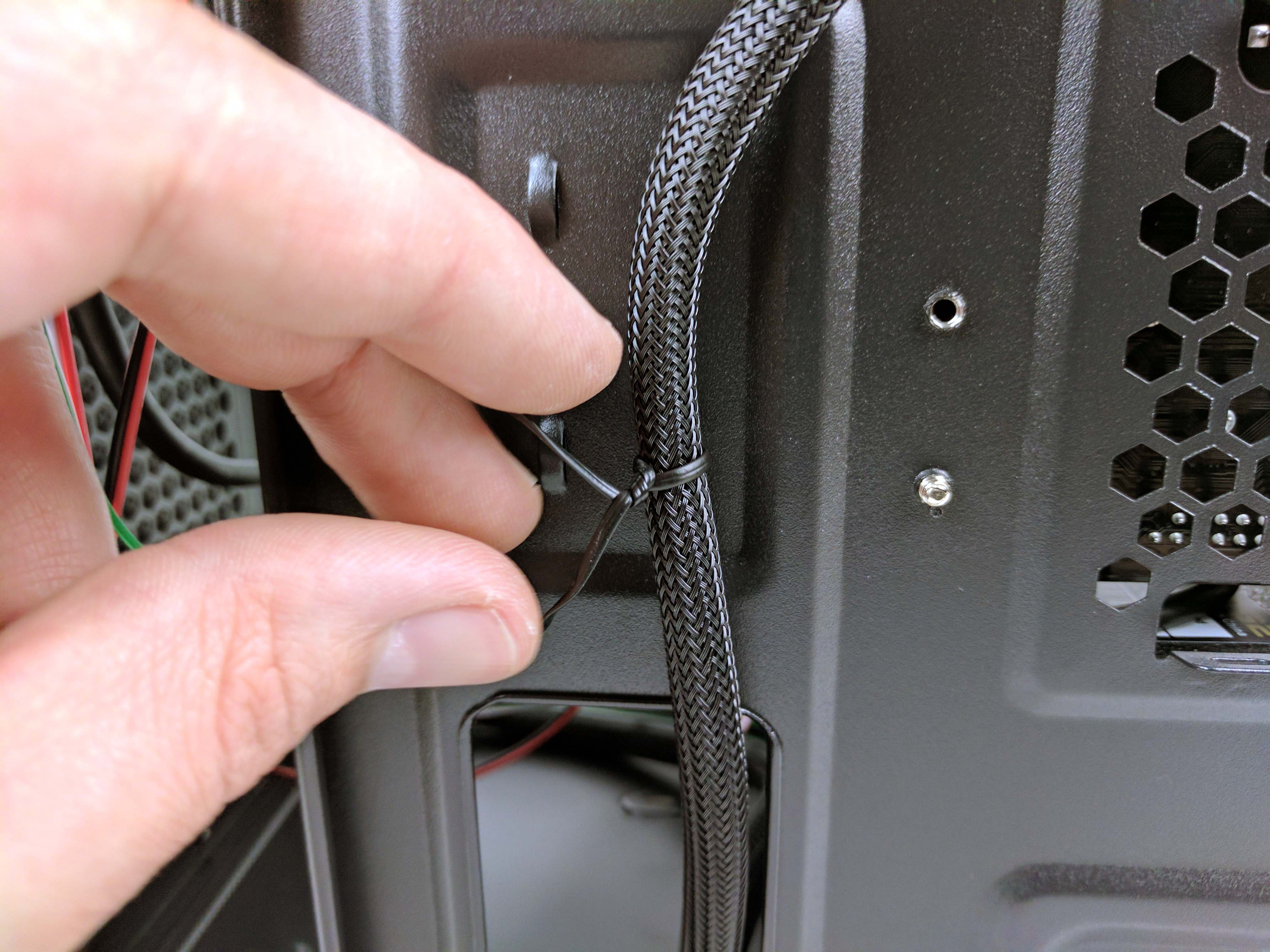
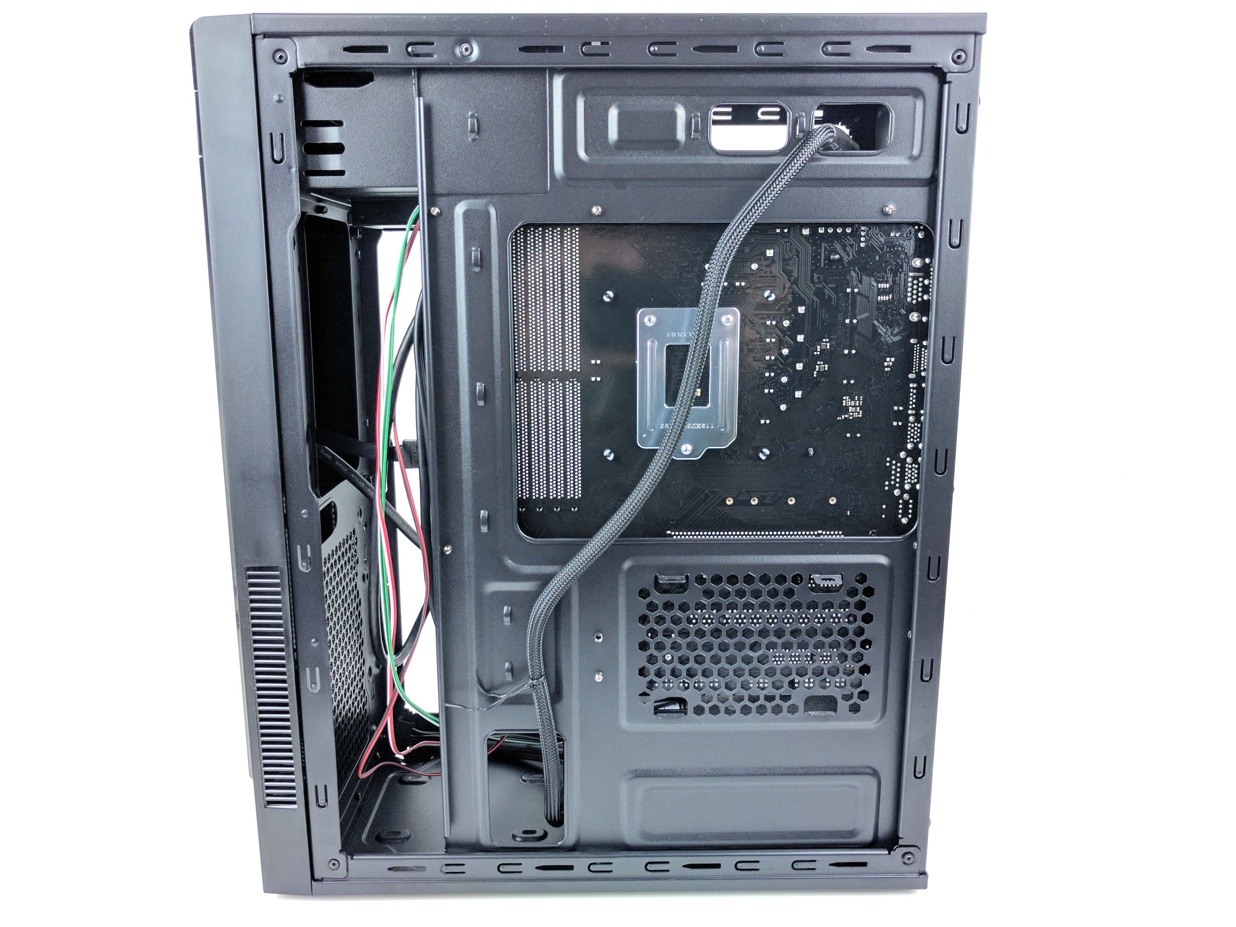
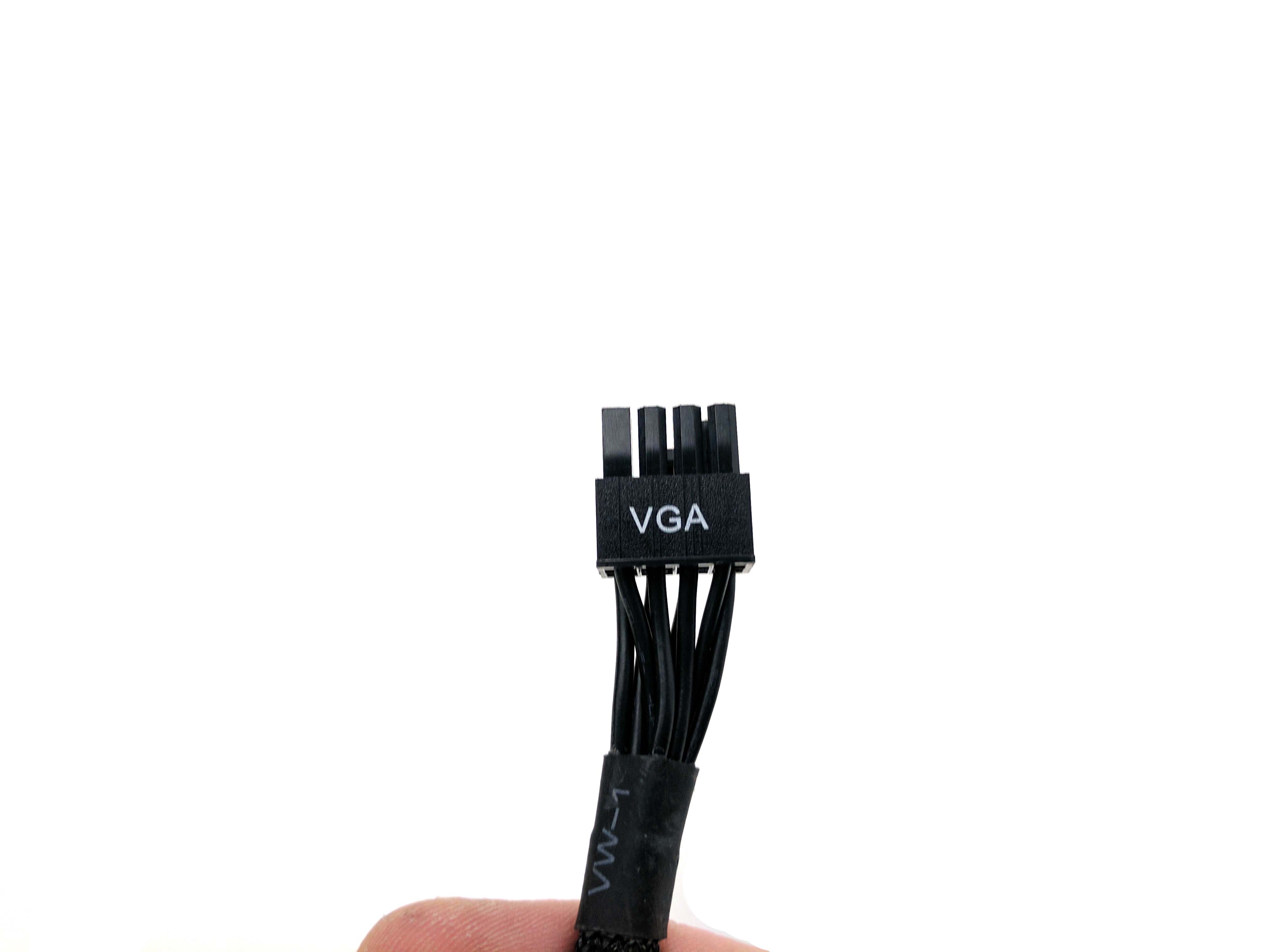
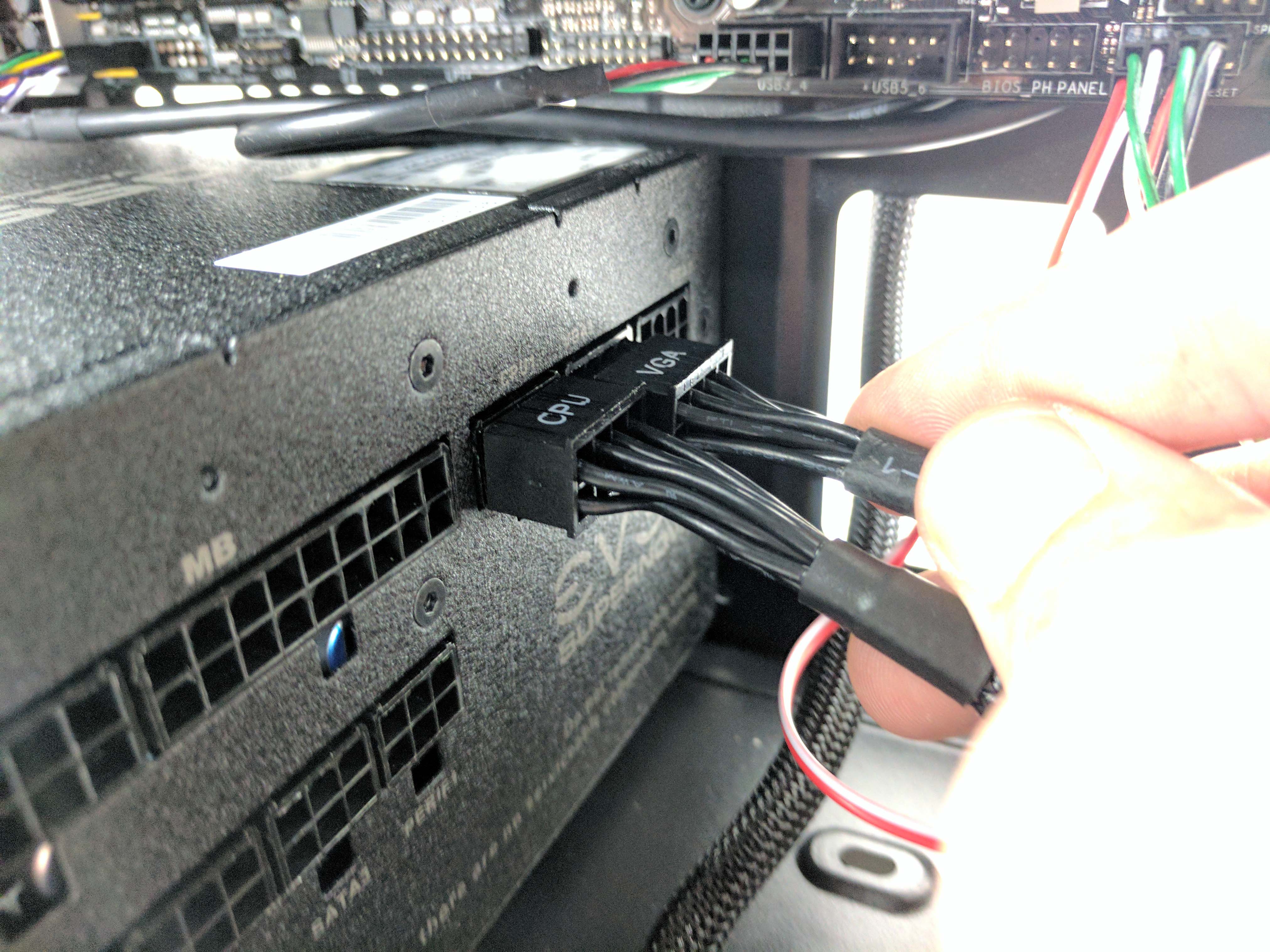
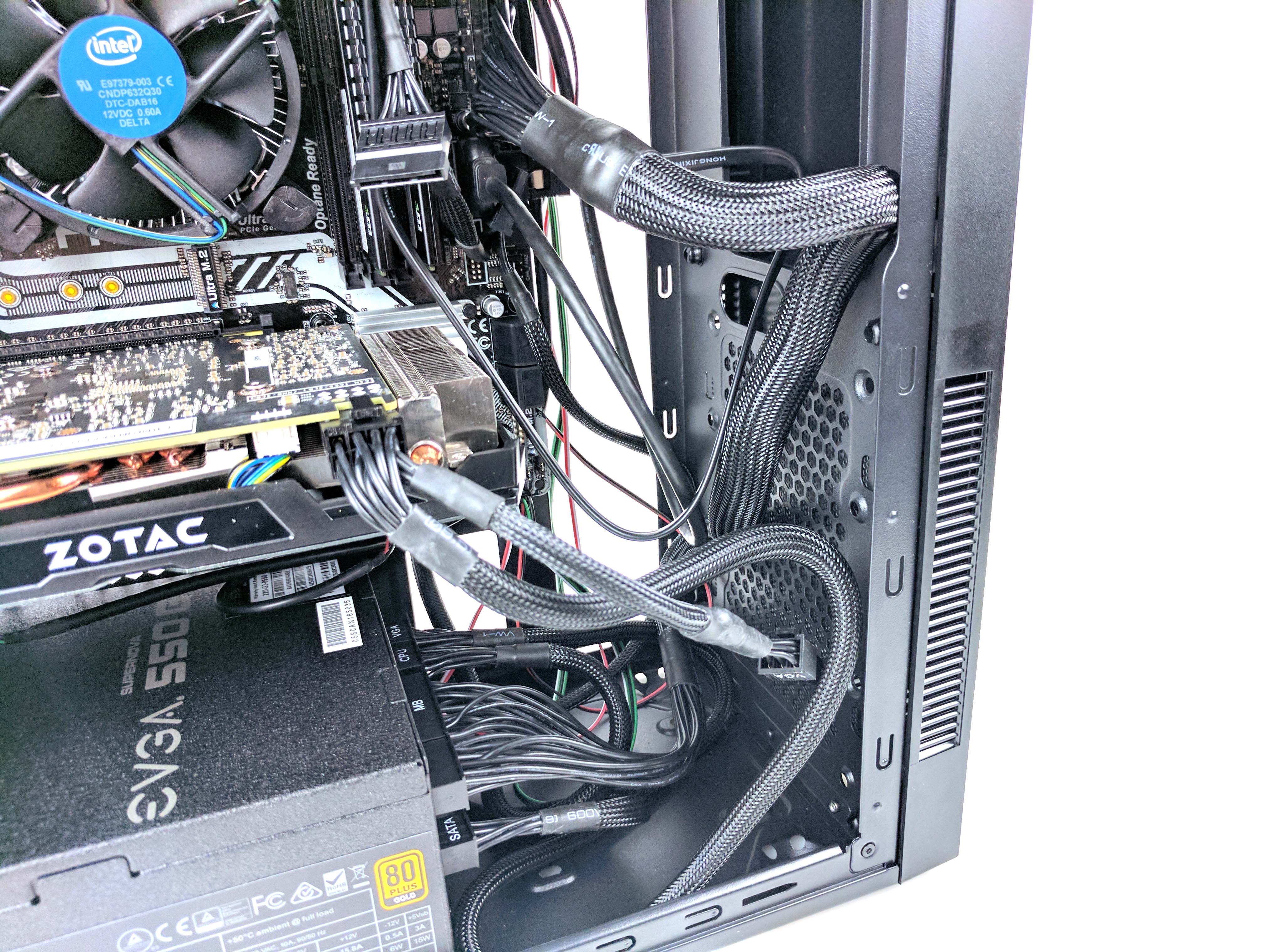
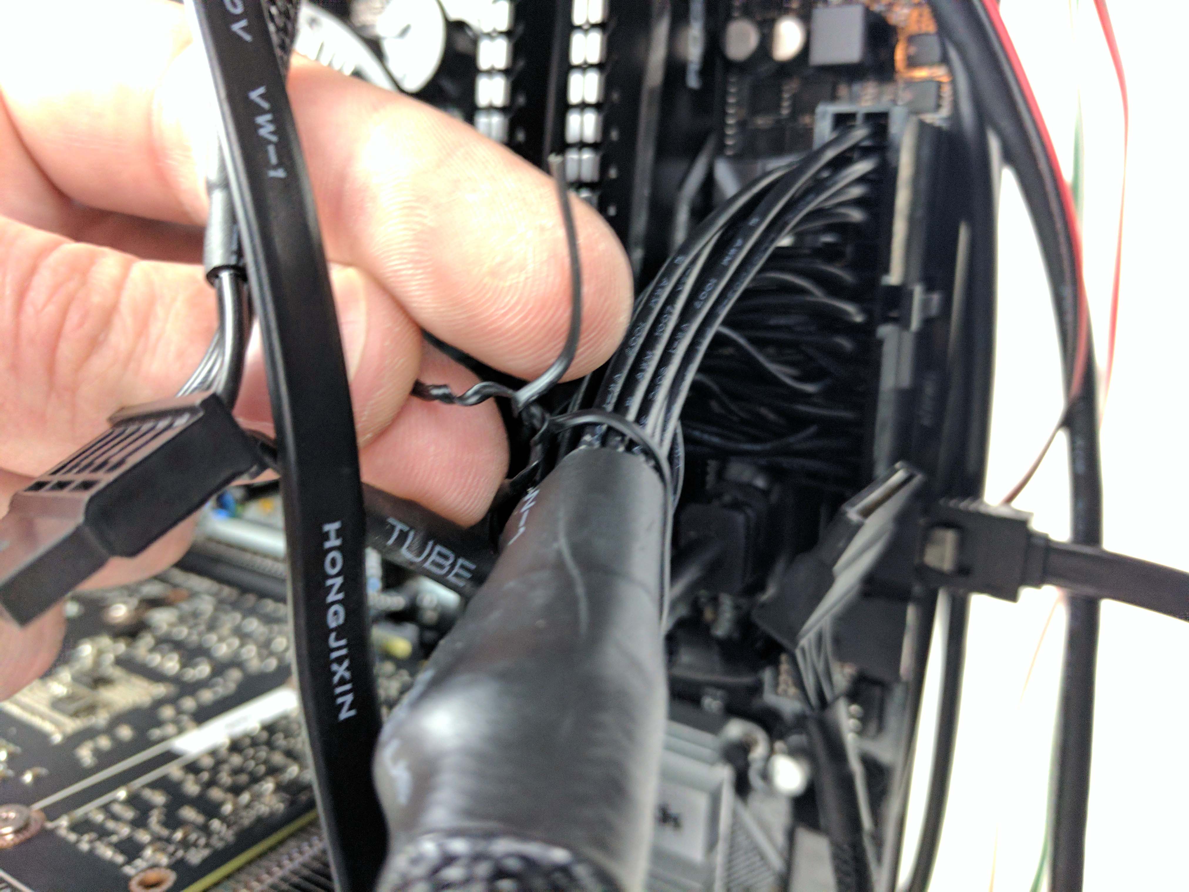
All that remains is the CPU, ATX, and PCIe power cables, which are incredibly easy to install thanks to their modularity. Start by plugging in the 8-pin (4+4-pin) CPU connector to the motherboard, then run the cable through the hole above the motherboard so that there’s not excess cable in the chassis (see the 4th picture below). Run the cable down the backside of the case and through the hole leading to the PSU. Plug in the CPU cable to the power supply and loop the excess wiring at the bottom of the case. Tie the cable down to the chassis using a tie wrap so that it’s as flush as possible with the case (see the 7th picture below).
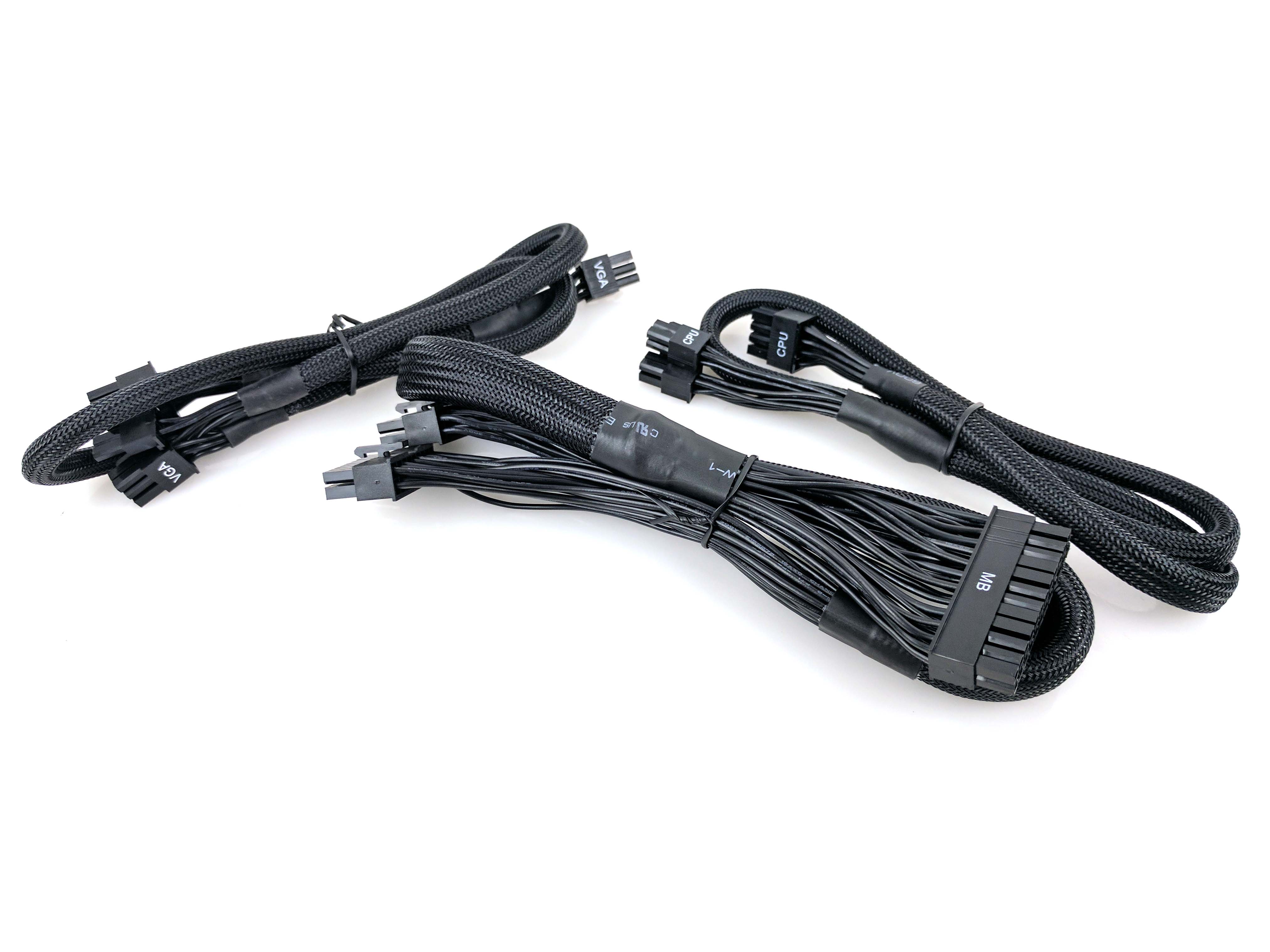
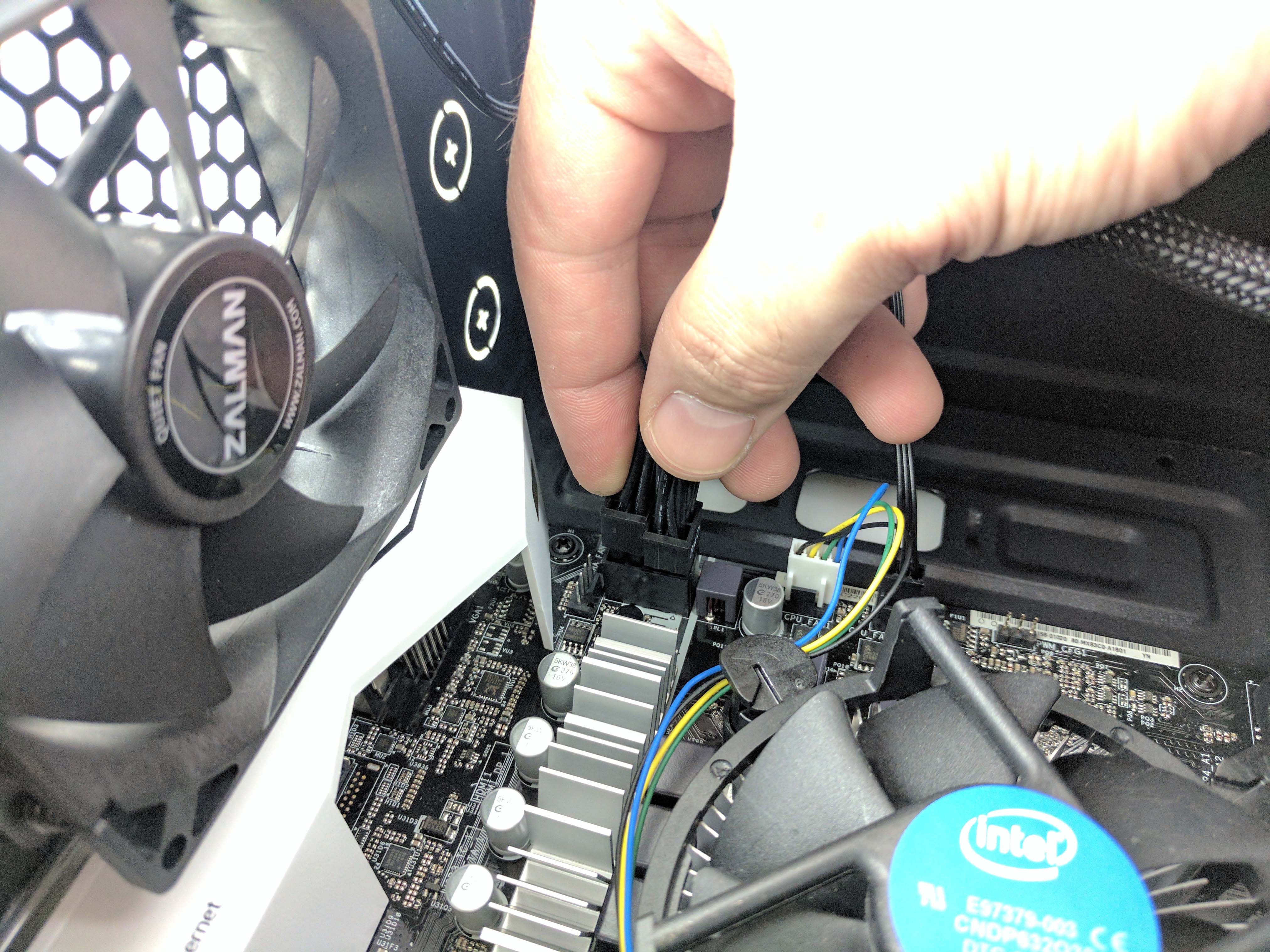
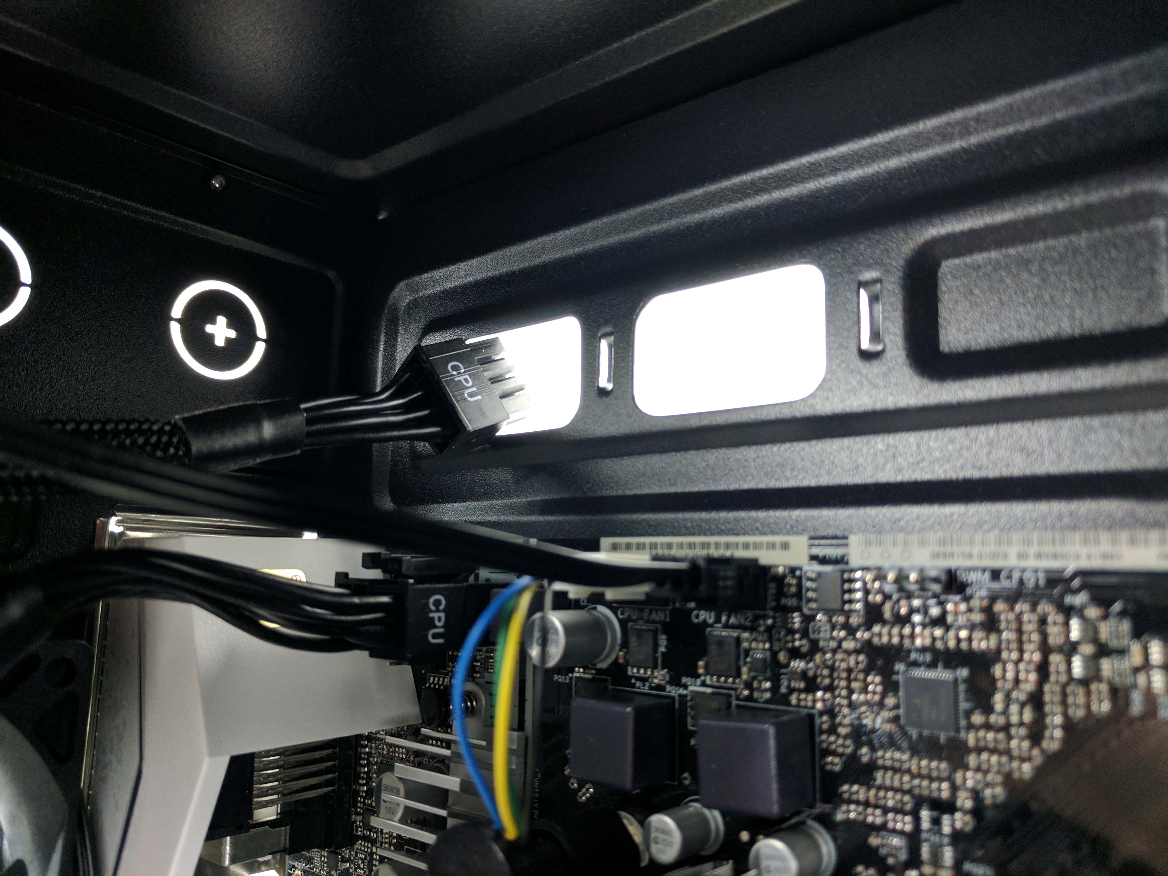
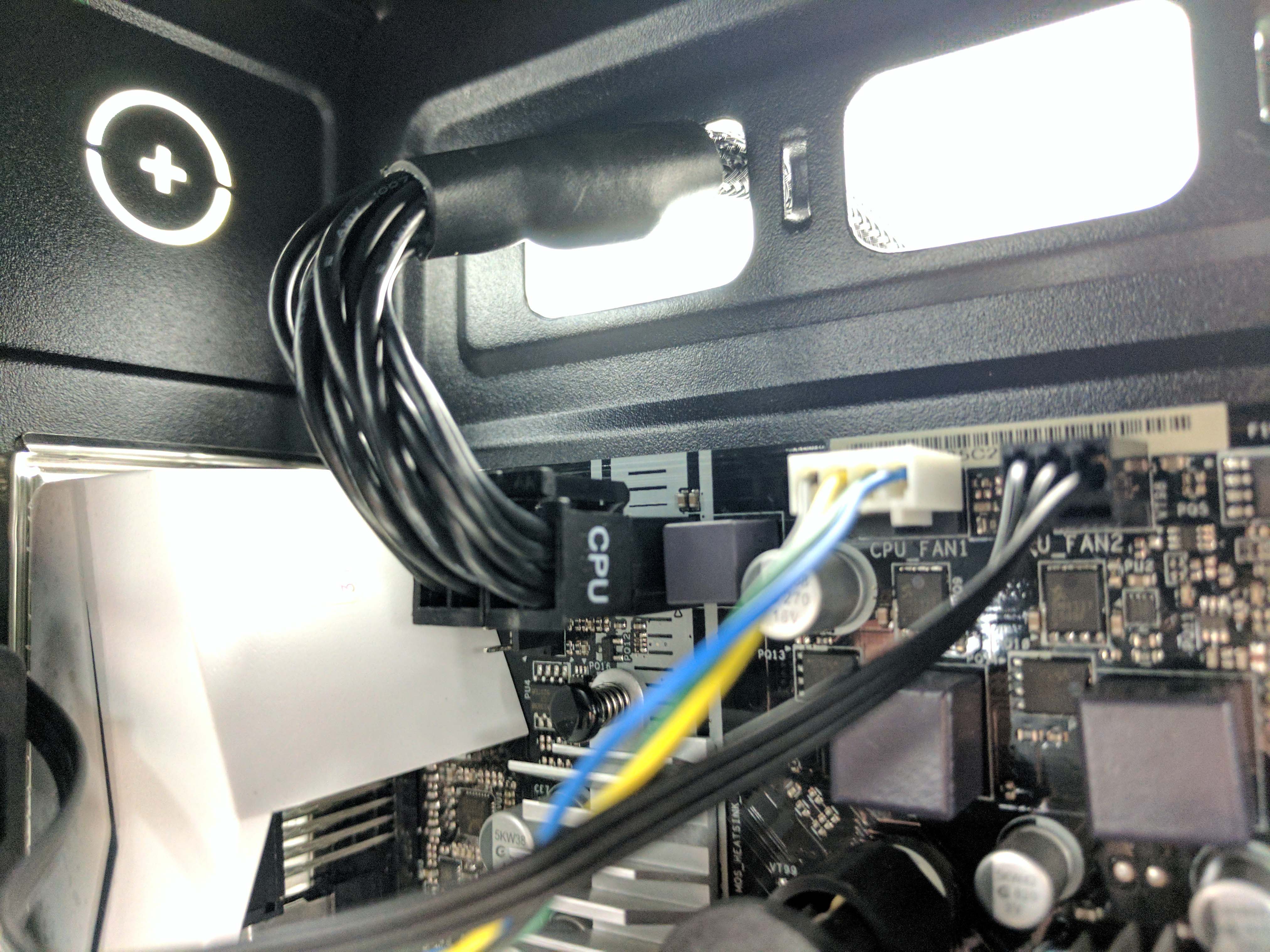
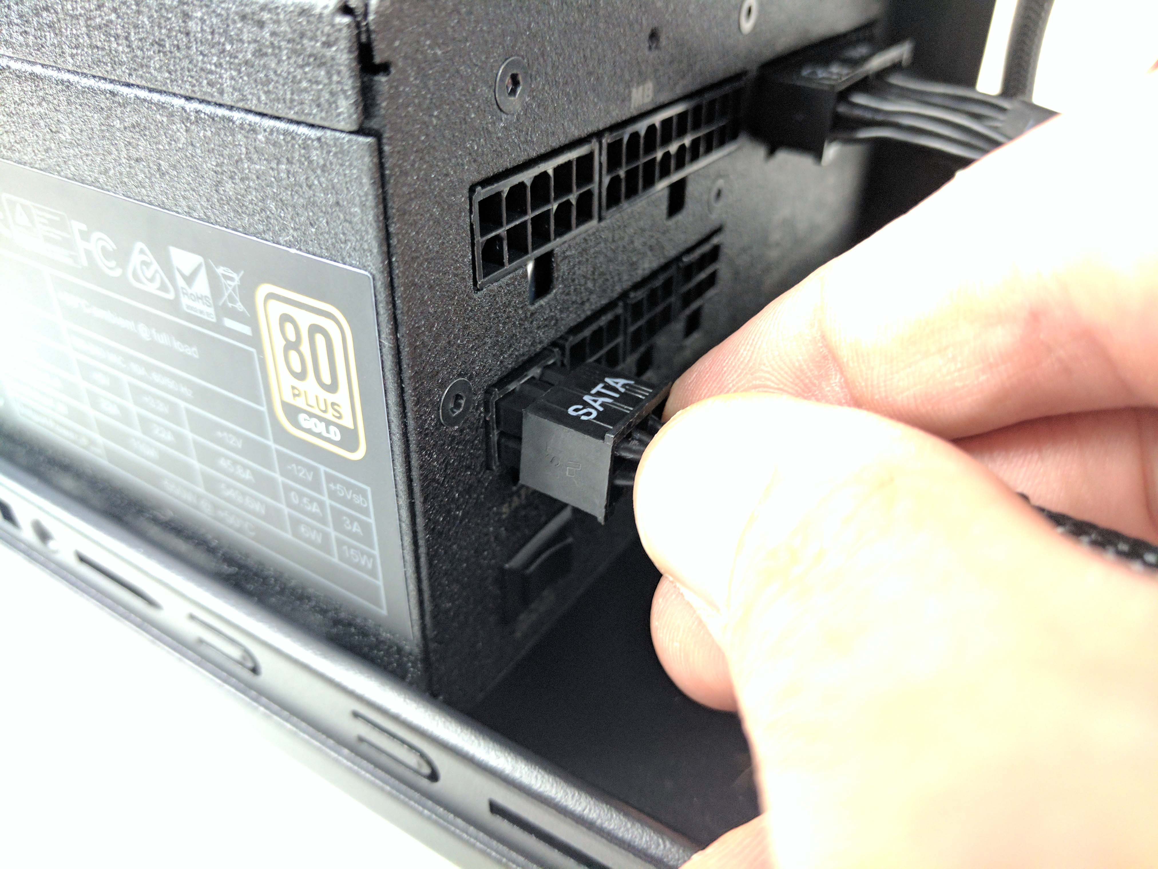
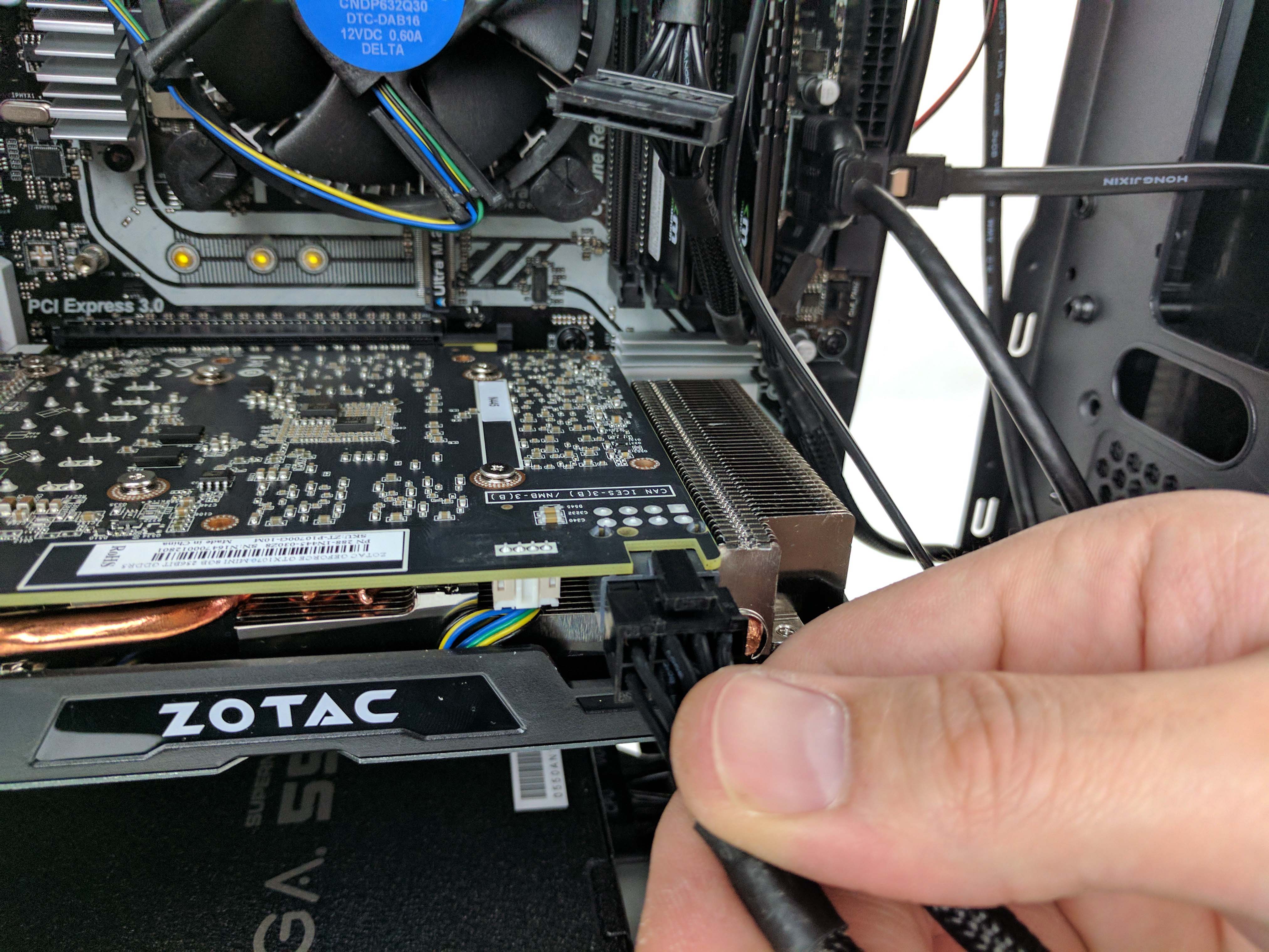
Plug the PCIe power cable into the PSU. Connect the SATA power plug we left hanging while you’re there. Run the PCIe power cable up to the graphics card and connect the first 6+2-pin cable in the line to the GPU (the 4th picture below). You can let the cables hang.
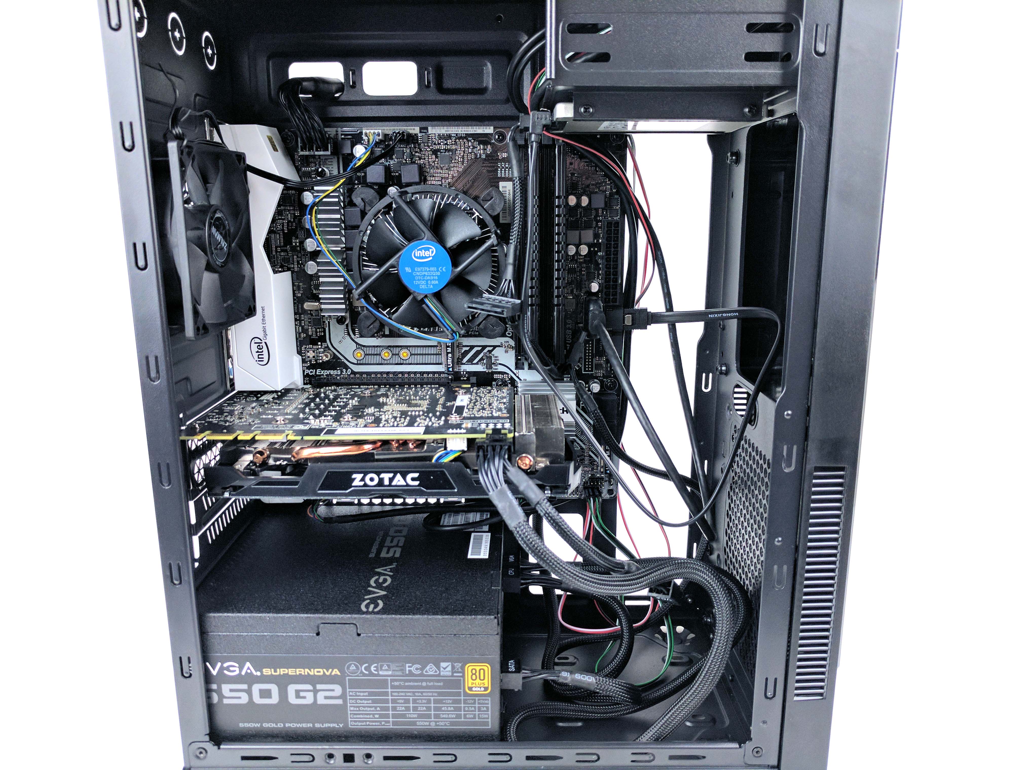
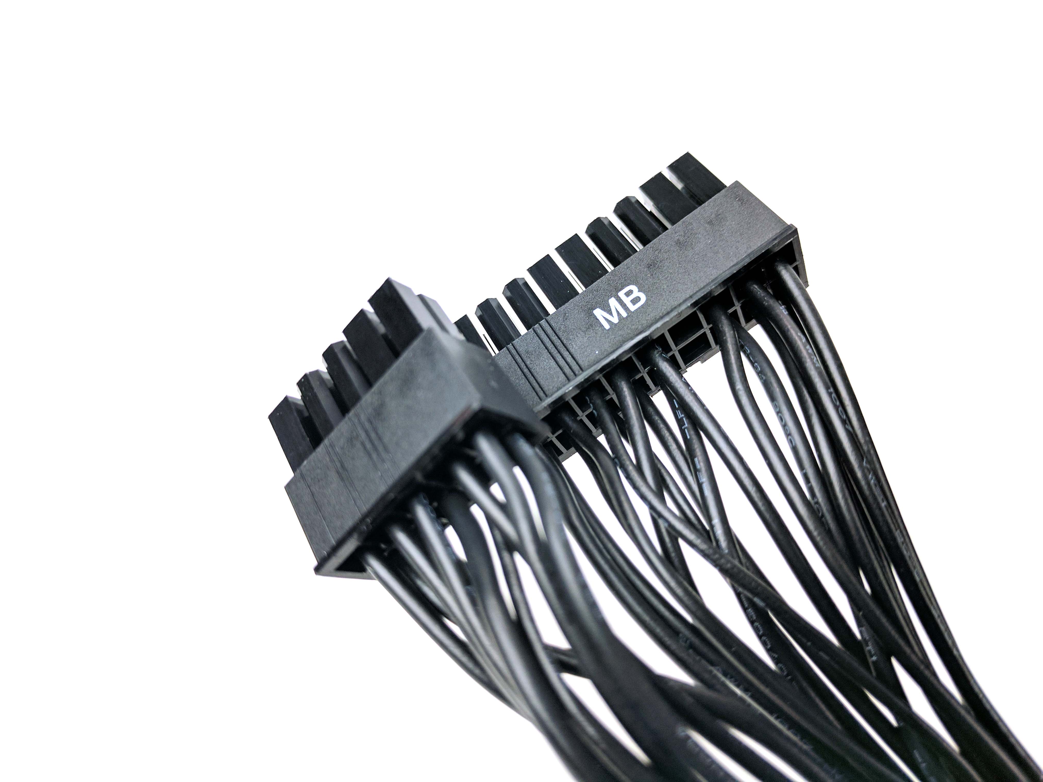
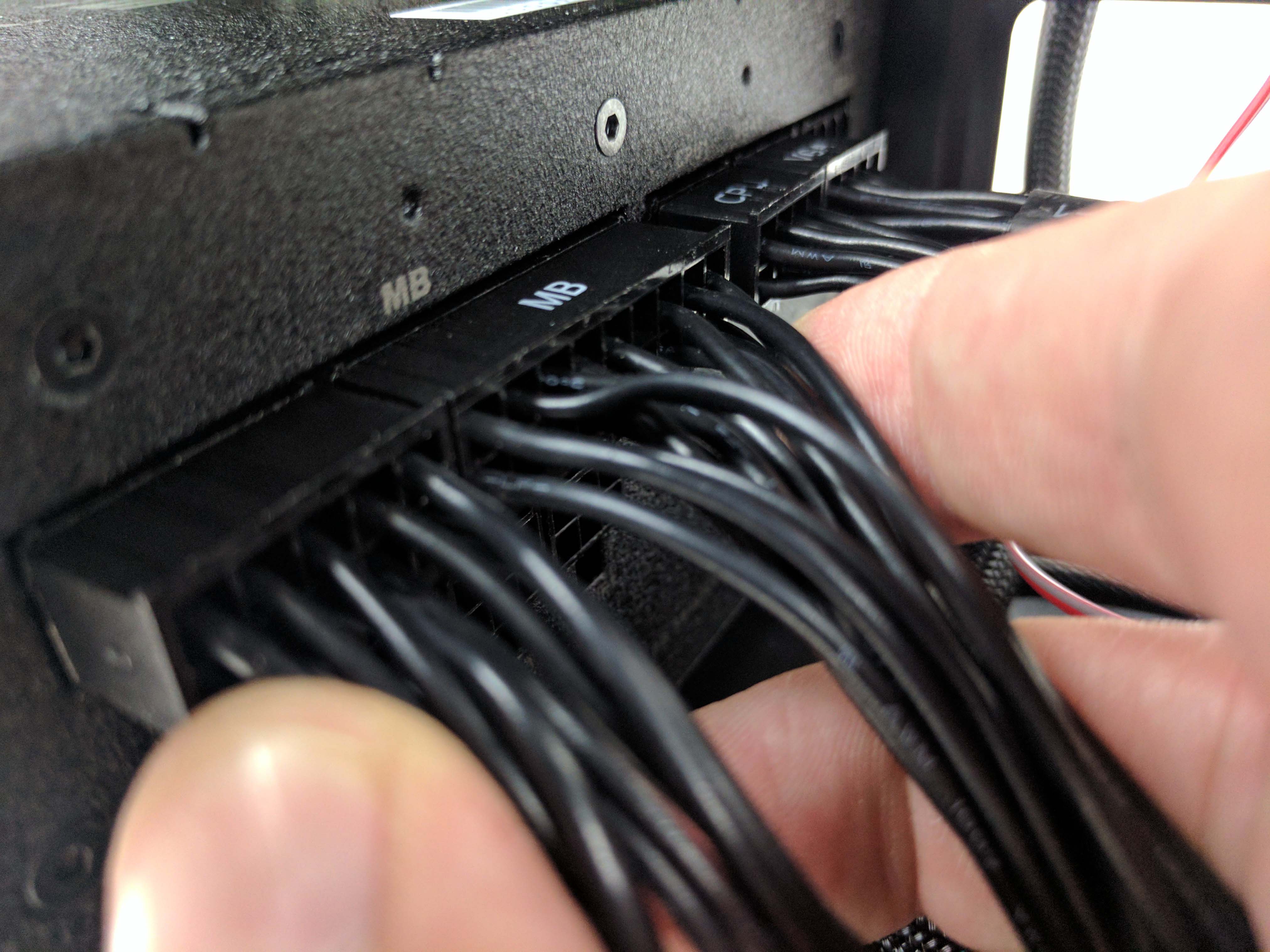
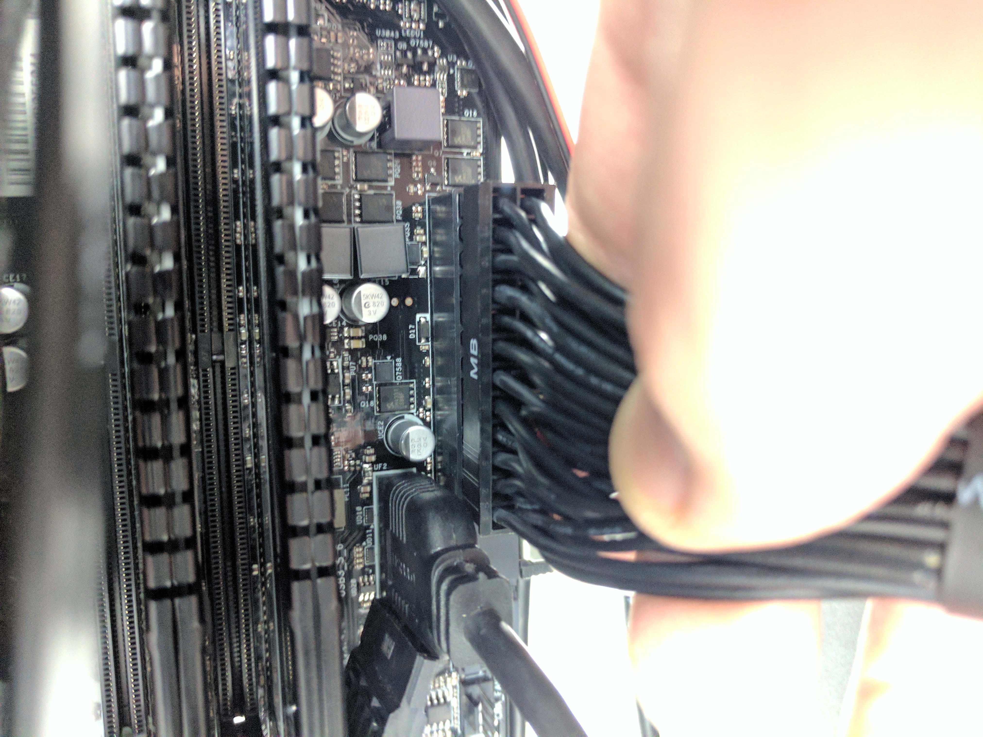
Finally, take the 24-pin ATX power cable (labeled “MB”) and connect it to the power supply (7th picture above). Run the cable up the chassis (behind the other cables) and connect it to the motherboard’s ATX plug (8th picture above). Again, leave the excess hang and loop it towards the bottom of the case as naturally as possible.
Finishing Touches
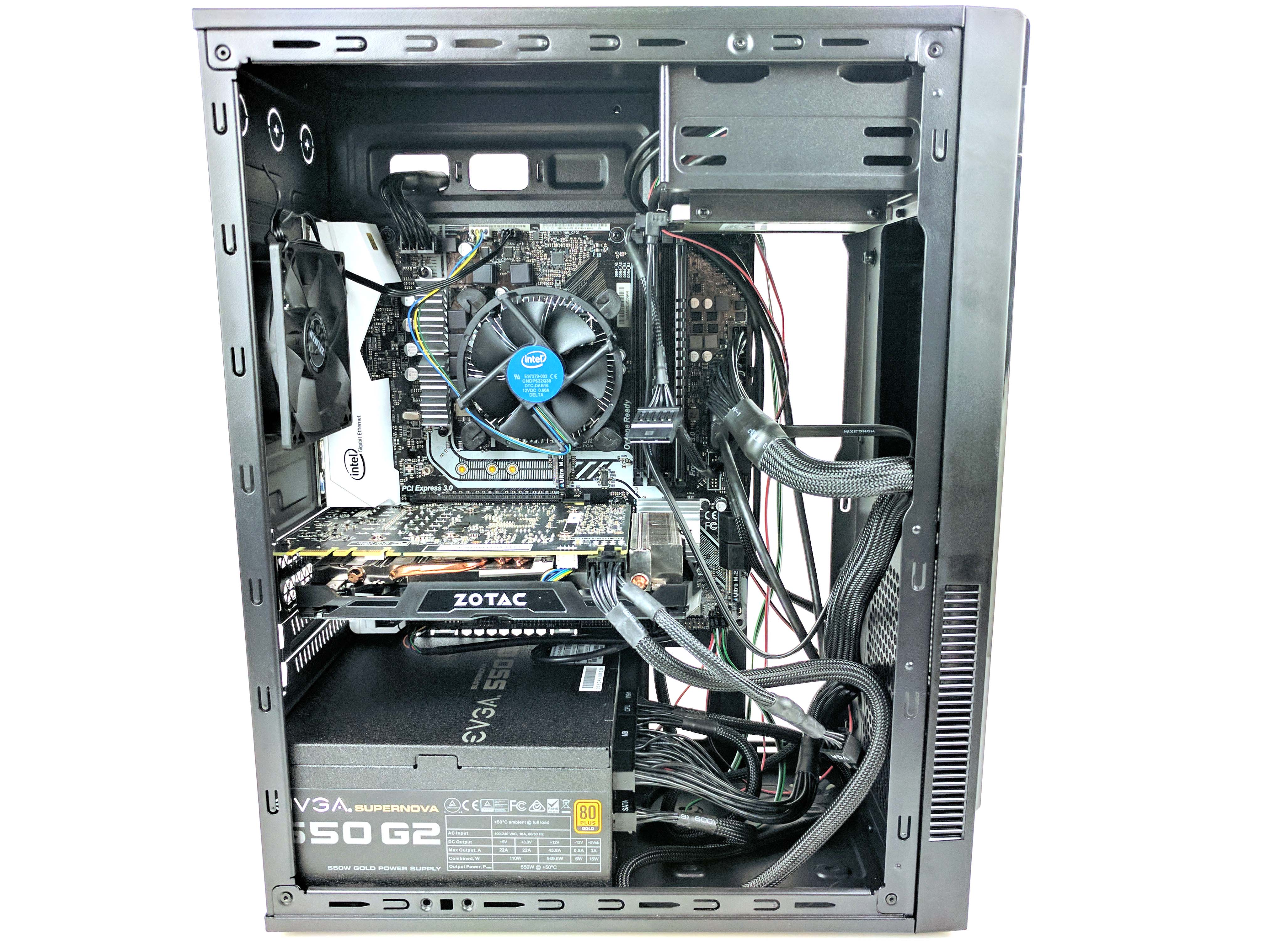
With all of the components installed, make sure that the cables are plugged in properly and tucked as best as they can be. This isn’t particularly important (the case has no windowed side panel), and the case has next to zero management options. However, tying them together at points will keep things somewhat neater than the mess of wires we find ourselves with at the end of this build. If you want to (we didn’t), replace the 3.5” drive bay before closing it up.
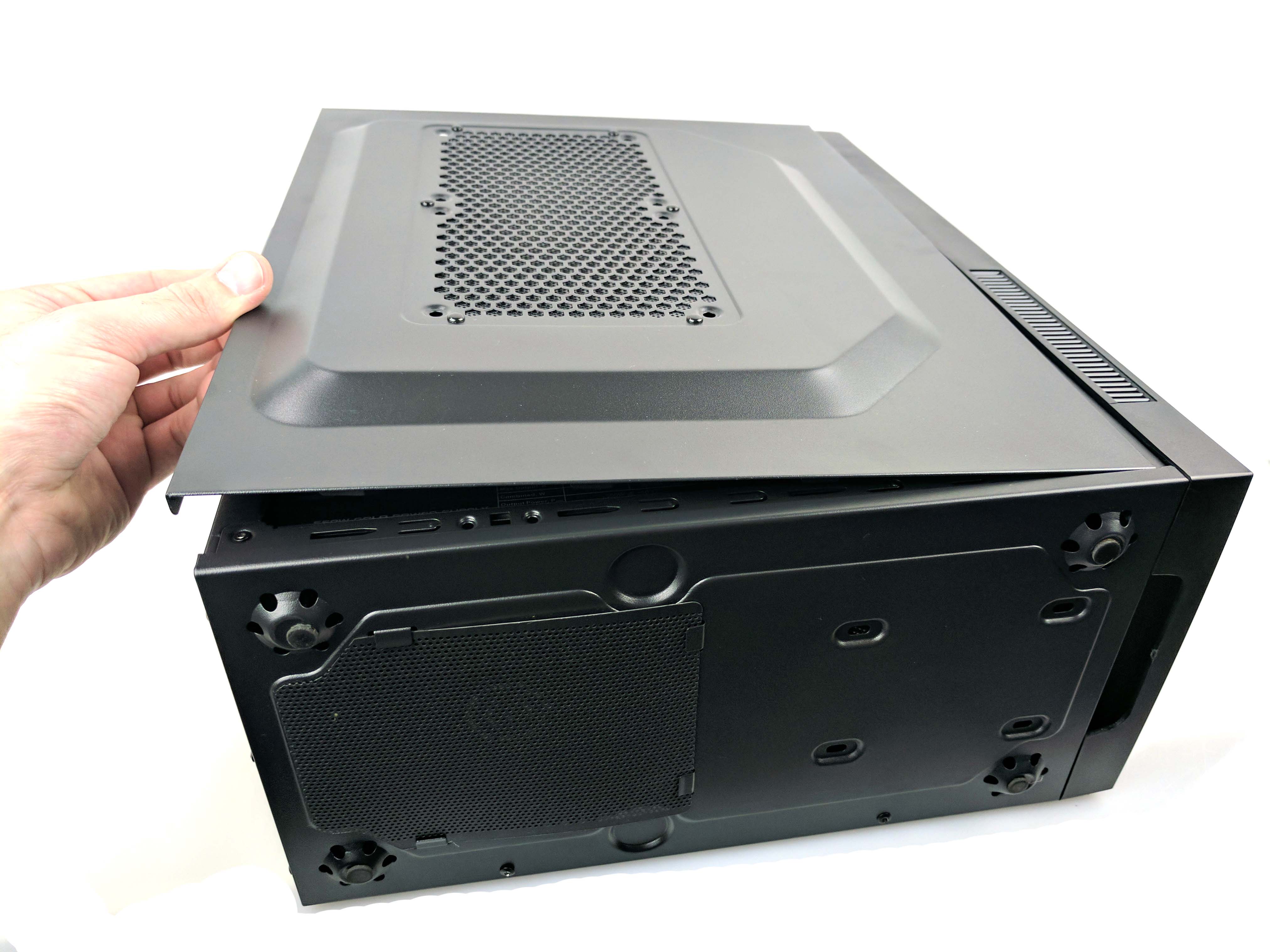
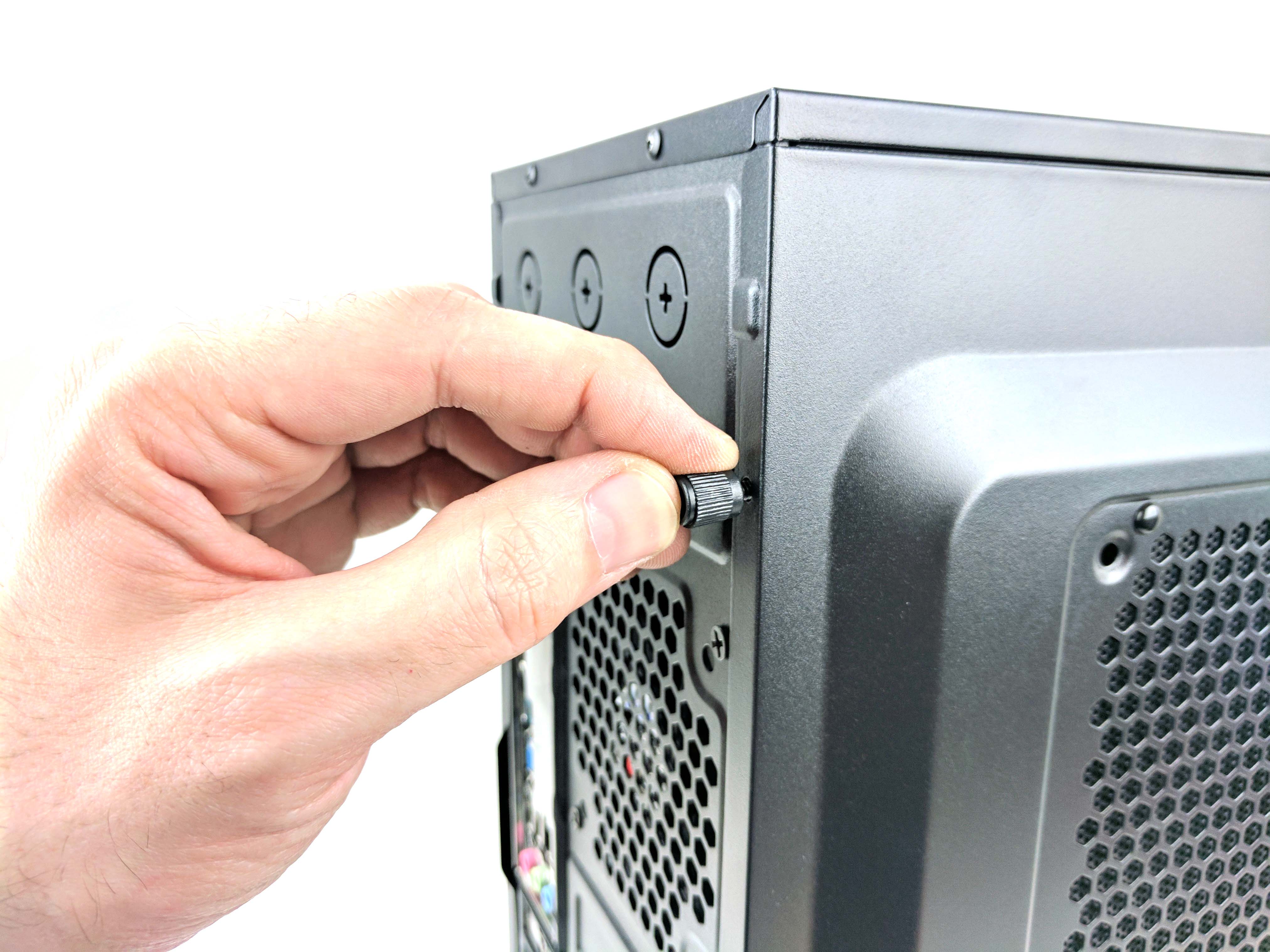
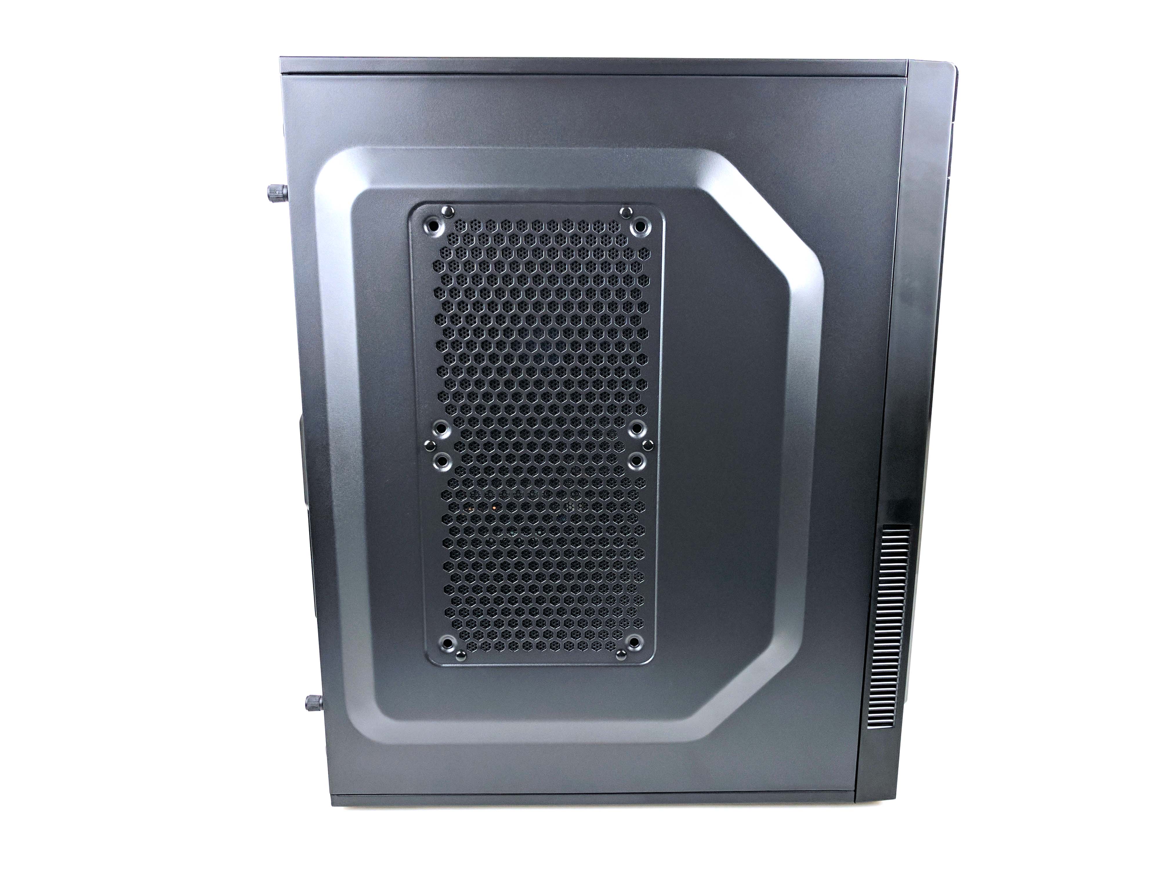
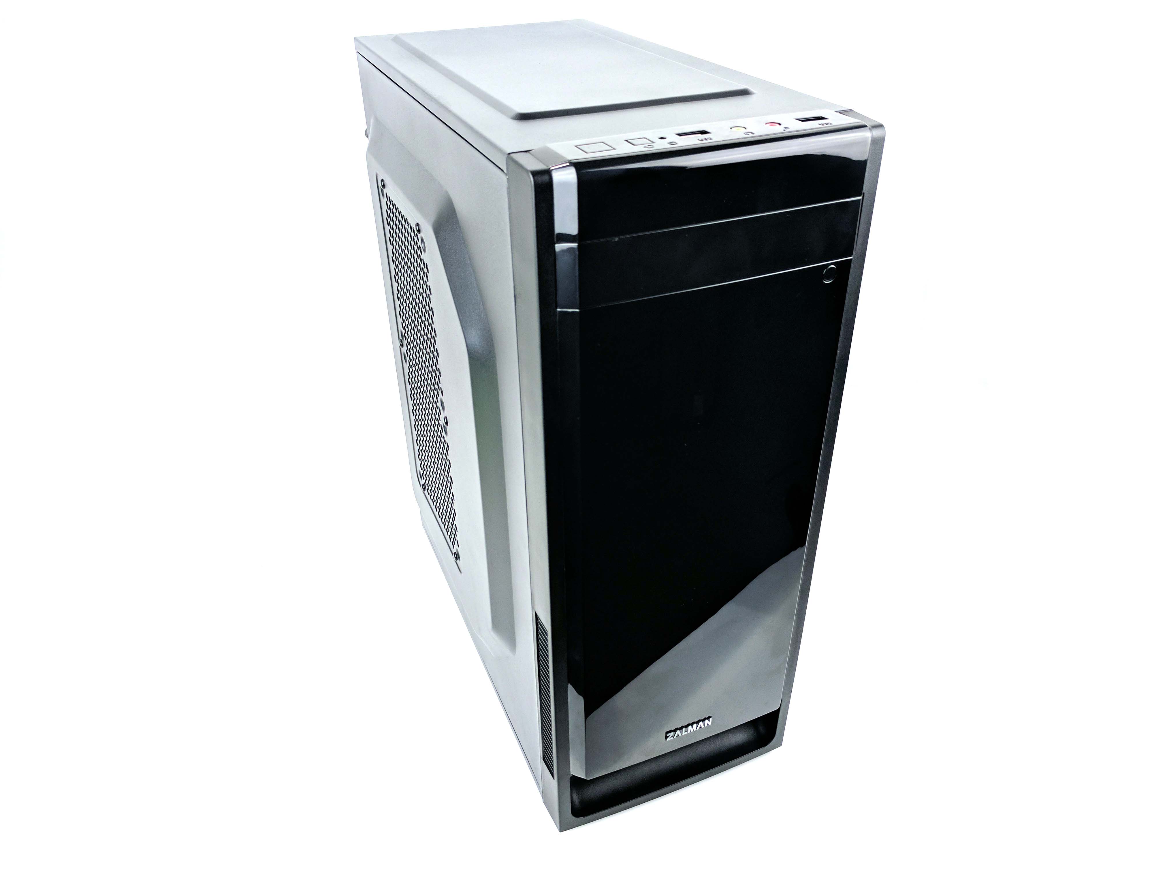
Replace the case’s side panels and secure them using the thumbscrews. Find a well-ventilated place to put your new gaming rig: the Best PC Build $1,000 can buy.
Setup Tips
Download the BIOS and all the latest drivers from ASRock’s website using a separate computer. This will ensure that you have the latest compatibility and performance updates.
To update the BIOS, unzip the BIOS file and place it on the root directory of a thumb drive. Plug the thumb drive into the new build and boot the machine. Press the F6 key to access ASRock’s BIOS update utility. The program will automatically recognize the BIOS and do most of the work for you with just a few clicks.
Without an unlocked CPU (or Z-series chipset), all you need to do is set the XMP memory profile by reentering the BIOS (by pressing F2). You can turn on XMP Profile 1 on the main screen (click on X.M.P.) then hit F10 to save and exit. Now you can load an operating system.
Benchmark Results
The Intel Core i5-7500 is clocked at 3.4 GHz with a boost frequency of 3.8 GHz in lightly threaded workloads, and the 16GB (2 x 8GB) Mushkin Blackline DDR4-2400 features CAS timings of 15-15-15-35. The Zotac GeForce GTX 1070 Mini 8GB graphics card sports clock speeds only slightly higher than the Nvidia Founder’s Edition GPU, with a base clock of 1518 MHz and a boost frequency of 1657 MHz.
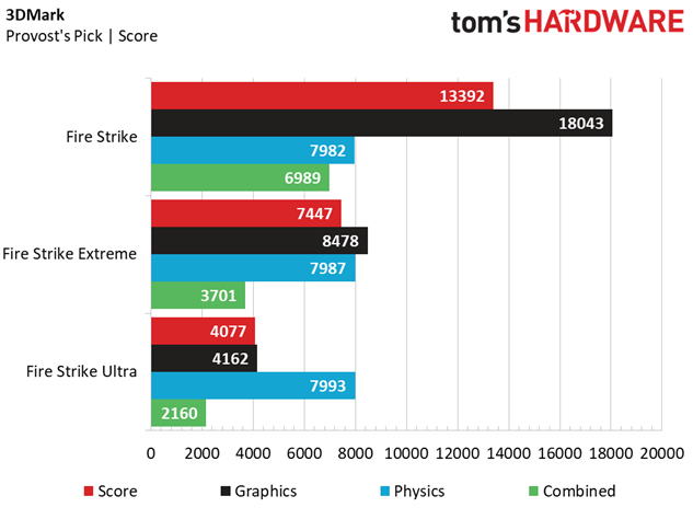
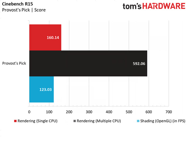
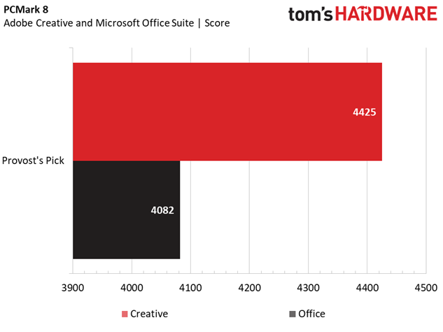
The $1000 Best PC Build performs admirably in our selected productivity benchmarks, with impressive scores in 3DMark Fire Strike that portend serious gaming chops for the dollar. However, these benchmarks also illustrate the limitations of the locked Intel Core i5-7500 processor with its Physics results, which fall in about 2,000 points behind our Best $750 PC Build (the unlocked Lava Stream). Similarly, Provost's Pick trails the Lava Stream in the Cinebench R15 test thanks to a lower peak CPU clockrate.
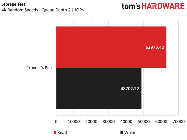
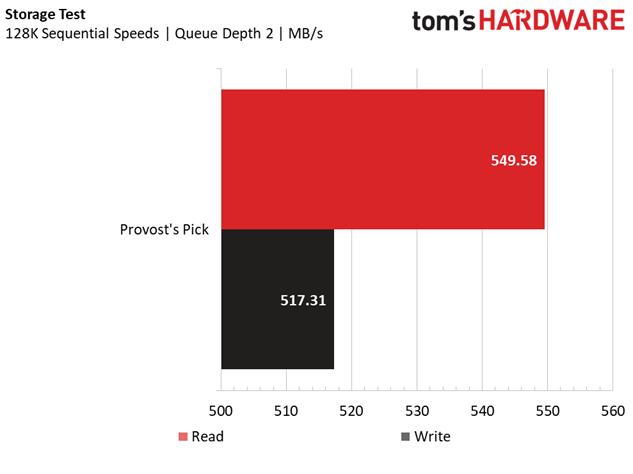
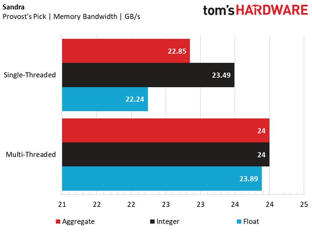
Provost's Pick is the first build in our lineup that features solid-state storage, and the 480GB OCZ Trion 150 SSD has impressive sequential and random read/write performance for a drive with TLC flash. The memory par for the course, running at its intended 2400 MHz on the Intel B250 motherboard; the Sandra Memory Bandwidth test scores aren't anything to write home about. However, the combination of quick storage and a dual-channel memory kit results in substantially higher scores in the Adobe Creative and Microsoft Office benchmarks of PCMark 8 (again, see the $750 Best Build, which doesn't have an SSD).
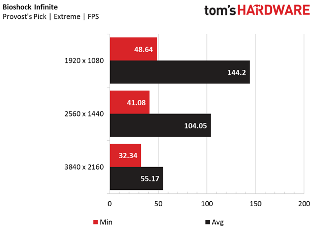
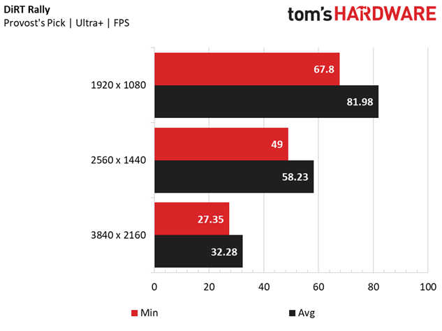
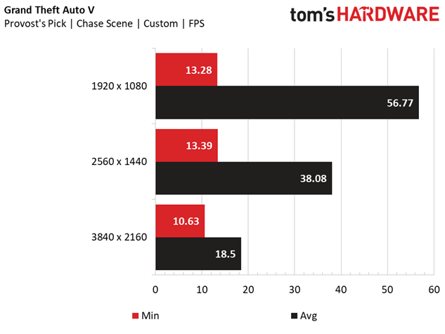
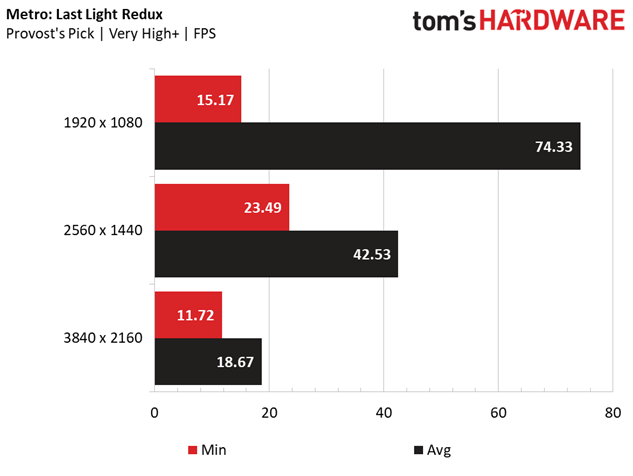
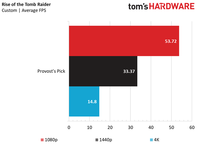
We kicked our game settings up to full throttle to match our desktop PC review suite, which means the highest detail and most punishing settings. This is where Provost's Pick shines; the budget was chiseled down in other areas (a locked CPU, case, a single SSD for storage) to leave enough cash for a Zotac GeForce GTX 1070 Mini, which gives the Best $1000 PC Build excellent graphics (and gaming) performance. At 1920 x 1080, Metro: Last Light Redux, DiRT Rally, and Bioshock Infinite have no trouble achieving over 60FPS. Even demanding titles including Rise of the Tomb Raider and Grand Theft Auto V put up decidedly playable framerates (50+ FPS) at the most intense graphics settings at 1080p.
If you are looking to dabble with higher resolutions, we wouldn't say that the GTX 1070 is a 4K gaming GPU, although there are games that you can easily achieve playable framerates (see Bioshock and DiRT). QHD seems like a better fit for Provost's Pick, with impressive performance across the gamut of our tests (at least 30+ FPS). Turning down the anti-aliasing and other detail settings will smooth out your gameplay, but you'd be hard-pressed to cram this level of graphics performance into a gaming rig for less money.
Final Analysis
$1,000 isn’t going to buy the best gaming rig in the world, but Provost's Pick won't let you down. The performance shelf between a $750 build and this $1,000 build is significant (go check out our Best $750 PC Build on the previous page), and the extra cash affords you faster storage, higher memory capacity, and a significantly more powerful graphics card. For the money, we wouldn’t change anything about the choice of CPU, motherboard, memory, or GPU, but there are similarly-priced choices on the AMD side, including the Ryzen 5 1600 at pretty much the same price point as the Core i5-7500. However, the B350 motherboard prices are running anywhere from $25 - $40 higher than Provost Pick board; to get the AM4 choice at this price point, you'll have to go with an A320 board (there's a similar ASRock offering at roughly the same price).
However, there were a few choices we'd advise against. The EVGA Supernova G2 550W is an excellent PSU, but we feel the modularity goes to waste when matched with the Zalman T2 case. Sure, it makes assembling the machine slightly easier, but ultimately, shaving a few dollars off the PSU (perhaps with a less-expensive 80 PLUS Bronze certified, semi-modular PSU?) would free up budget for some of the other troublesome parts of the build.
We did not enjoy working with the Zalman T2 case (we gave it a fair chance, too). Despite Zalman’s inexpensive approach to a mini-tower, we’d highly recommend going with a different micro-ATX chassis. The lack of cable management doesn’t hurt the overall presentation (still, no windowed side panels), but it was difficult to get the PSU and rear I/O backplate to fit properly, and everything felt flimsy and cheap. A few more dollars thrown at the case (maybe someone can get one with window, finally?) would improve what we feel is the biggest weakness of this build.
The 480GB OCZ Trion 150 SSD is a speedy entry-level TLC flash drive, but if you can manage to squeeze a few more dollars into your budget (or free it up by swapping PSUs), an MLC SSD would likely give you more longevity. An additional 1TB HDD would also give you a place to store your regular files - those that don’t necessarily need the speed of an SSD, reducing the read and writes on the drive, perhaps adding to its longevity. There are also cheap M.2 NVMe SSD options out there if you want to take full advantage of the 200-series motherboard’s features.
MORE: Best PC Builds
MORE: How To Build A PC
MORE: All PC Builds Content
Derek Forrest was a contributing freelance writer for Tom's Hardware. He covered hardware news and reviews, focusing on gaming desktops and laptops.
