Rosewill Photon-1200 PSU Review
Today, we evaluate Rosewill's Photon-1200, manufactured by Sirfa, featuring fully modular cabling, Gold-rated efficiency and a high watt-per-dollar ratio.
Why you can trust Tom's Hardware
Transient Response Tests
Advanced Transient Response Tests
For details on our transient response testing, please click here.
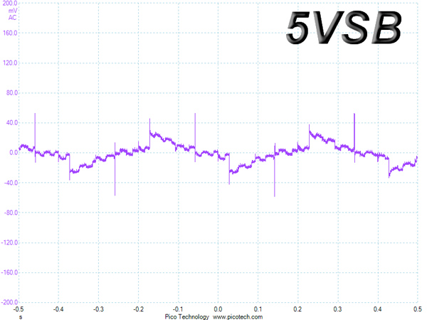
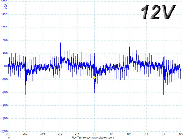
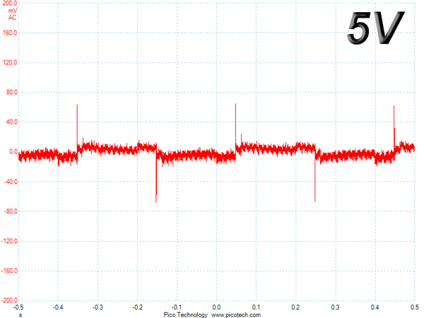
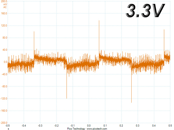
In these tests, we monitored the PSU's response in two different scenarios. First, a transient load (10A at +12V, 5A at 5V, 5A at 3.3V and 0.5A at 5VSB) was applied for 200ms while the supply was working at 20 percent load. In the second scenario, we hit it with the same transient load while operating at 50 percent capacity. In both tests, we used our oscilloscope to measure the voltage drops caused by the transient load. The voltages should have remained within the ATX specification's regulation limits.
These tests are crucial because they simulate the transient loads a PSU is likely to handle (such as booting a RAID array or an instant 100 percent load of CPU/GPUs). We call these tests Advanced Transient Response Tests, and they are designed to be tough to master, especially for a PSU with a capacity of less than 500W.
Advanced Transient Response at 20 Percent
| Voltage | Before | After | Change | Pass/Fail |
|---|---|---|---|---|
| 12V | 12.275V | 12.188V | 0.71% | Pass |
| 5V | 5.155V | 5.075V | 1.55% | Pass |
| 3.3V | 3.360V | 3.241V | 3.54% | Pass |
| 5VSB | 5.120V | 5.063V | 1.11% | Pass |
Advanced Transient Response at 50 Percent
| Voltage | Before | After | Change | Pass/Fail |
|---|---|---|---|---|
| 12V | 12.210V | 12.118V | 0.75% | Pass |
| 5V | 5.132V | 5.061V | 1.38% | Pass |
| 3.3V | 3.340V | 3.221V | 3.56% | Pass |
| 5VSB | 5.083V | 5.045V | 0.75% | Pass |
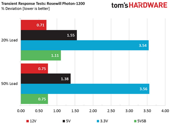
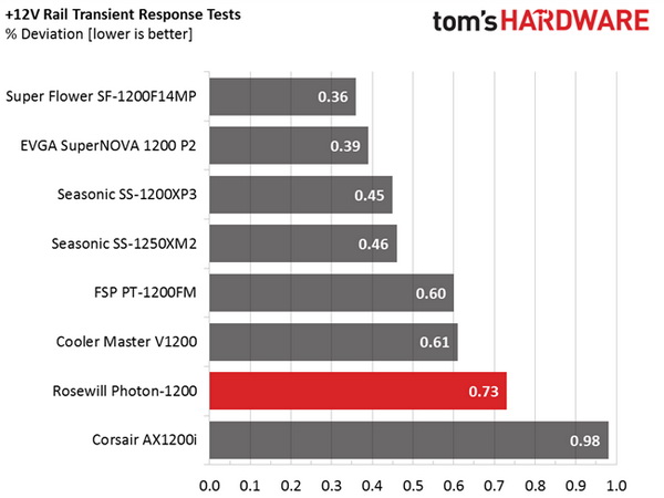
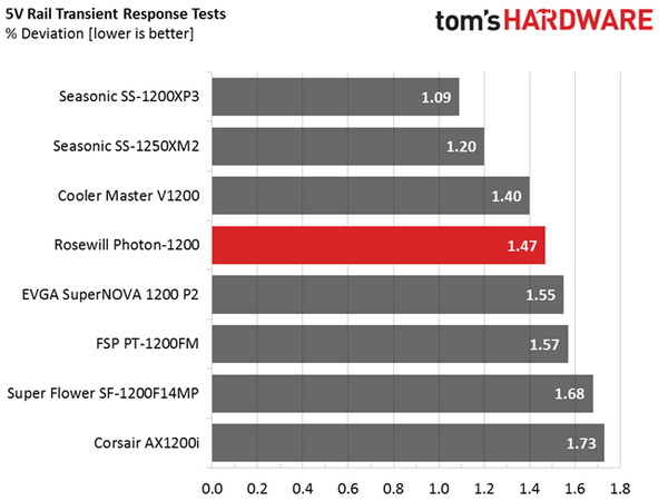
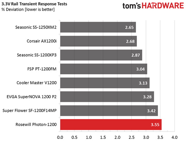
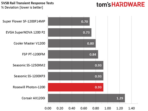
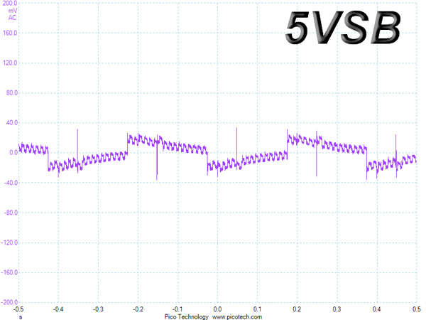
Performance in these tests was pretty good; the +12V rail stayed well below one percent in both cases, while deviations on the other rails were normal for this PSU's capacity. Ideally, we would like to see a deviation within three percent at 3.3V; however, this rail is lightly used by modern systems, so we are satisfied by the 3.56 percent result.
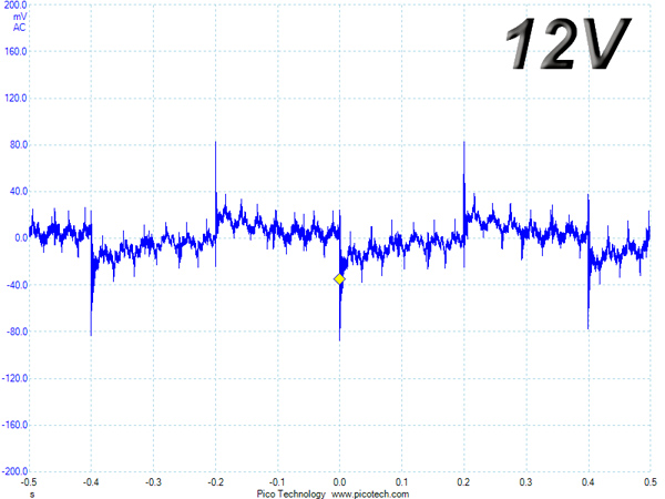
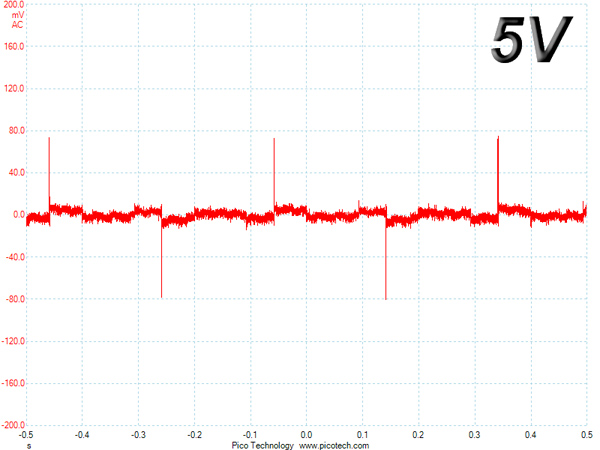
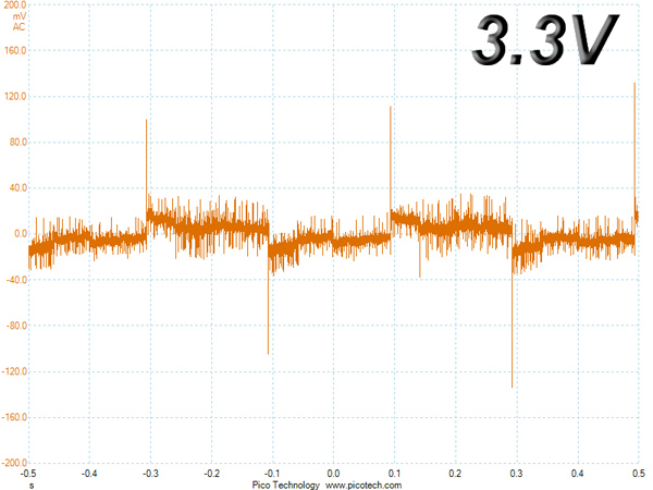
Here are the oscilloscope screenshots we took during Advanced Transient Response Testing:
Transient Response At 20 Percent Load
Transient Response At 50 Percent Load
Turn-On Transient Tests
In the next set of tests, we measured the response of the PSU in simpler transient-load scenarios—during its power-on phase.
For the first measurement, we turned the supply off, dialed in the maximum current the 5VSB could output and switched on the PSU. In the second test, we dialed the maximum load the +12V could handle and started the PSU while it was in standby mode. In the last test, while the PSU was completely switched off (we cut off the power or switched off the PSU by flipping its on/off switch), we dialed the maximum load the +12V rail could handle before switching on the PSU from the loader and restoring power. The ATX specification states that recorded spikes on all rails should not exceed 10 percent of their nominal values (+10 percent for 12V is 13.2V, and 5.5V for 5V).
Get Tom's Hardware's best news and in-depth reviews, straight to your inbox.
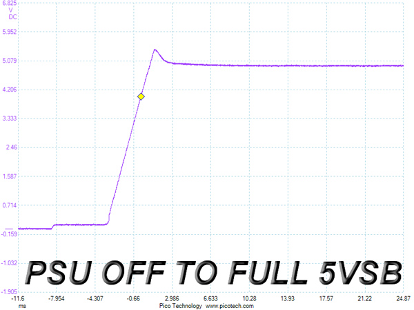
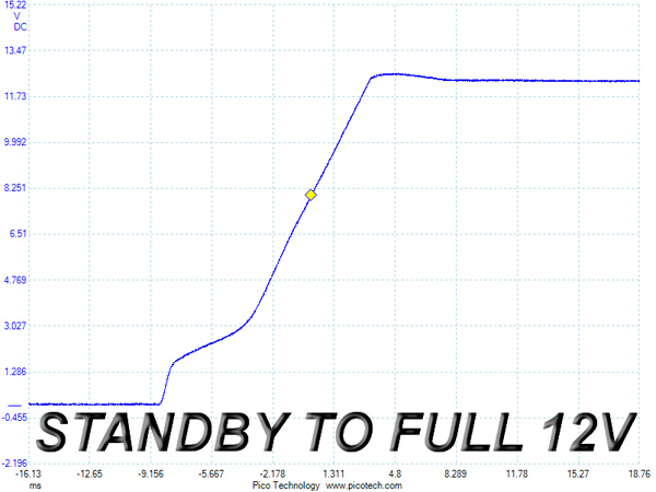
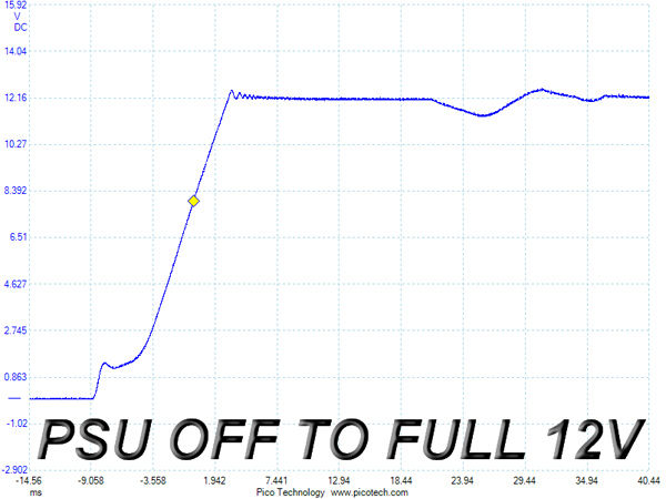
At 5VSB, the spike was quite high at 5.46V, reaching close to the ATX spec's upper limit. Sirfa should look into this. On the "standby to full +12V" load test, performance was good, while in the last test we noticed a pretty low voltage overshoot and a small dive at the start of the waveform.
Overall, we'll call this performance mediocre, with the most significant problem being the 5VSB spike.
Current page: Transient Response Tests
Prev Page Cross-Load Tests And Infrared Images Next Page Ripple Measurements
Aris Mpitziopoulos is a contributing editor at Tom's Hardware, covering PSUs.
-
MasterMace Sirfa has produced too many poor units in the past to get any leeway or benefit of the doubt. It failed 80 Plus Gold in the hotbox at 100% load.Reply -
boller I have a good perspective on that ripple thing: just finished repairs of a PC power supply and when I was measuring ripple I found it was out of whack (300 mV pp). After some investigation I found out that measuring ripple is a tricky thing. Tom's description on how they do it is very incomplete. Eevblog guy spent an entire episode on ripple. In my case I had to do this: limit oscilloscope bandwidth 20 MHz, instead of the grounding clip use that spring attachment and measure loaded PSU at the last cap before leads. Ripple went down from 300 to 48 mV pp.Reply -
Aris_Mp First of all you don't just hook a scope on a PSU's output and measure ripple else you will catch huge spikes, like in your case, which will totally alter the measured result.Reply
Secondly most users aren't interested on how I do things (and even if I elaborated on all the procedures I follow only a fraction of them would understand them) but about the final result. For me the most important is to explain what ripple is and how it can affect the components of a system.
Thirdly. You don't have to watch Dave to see how ripple is measured properly. You can check on the ATX spec which includes the ripple measurement procedure. I follow all guidelines of the ATX spec so if you need to see how I measure ripple or load regulation just take a look at them. In any case the following scheme will show you how to measure ripple on a PSU.
-
boller No need to be defensive, I was just pointing out that your _description_ is incomplete, not that you do it wrong. Although it would be nice for you to place a note over there saying that actual procedure involves some additional caps and an honest to god differential probe (!)Reply -
Aris_Mp I just replied to your concerns. No need to think that I am defensive because clearly this is not the case with me.Reply
I already stated that I don't mention how I measure ripple since among others all of us reviewers have to follow the ATX spec procedure. There is no point in repeating the whole ATX spec from the moment that anyone can download and read this spec with a simple google search.
Besides these two caps (which are already pre-installed on the fixtures that most of us reviewers have. There also present on loaders like the Sunmoon ones) and the good quality probes you also need to isolate all external noise that can pass from the PSU's EMI filter. In other words you need to provide "clean" power to the PSU. Personally I do this with a Chroma AC source and in the near future I plan to get a online UPS with some extra circuits for EMI/noise protection which will feed the AC source (so I will have two layers of protection). In order to check if your line is clean firstly take some readings on the major rails (+12V, 5V and 3.3V) with the PSU in standby. If you see increased ripple (normally it should be close to zero mV) then your scope picks up noise or the PSU isn't properly isolated from the rest devices on your home/lab. -
CTurbo It's not a bad unit, but it's not competitive at all. It's more expensive than an EVGA G2 1300w Gold and and Rosewill Capstone 1200w Gold, and almost as much as an EVGA P2 1200w. Yikes!Reply -
Mac266 Shame it performed badly, a cheap high rated supply could stir the market up nicely!Reply
It's not a bad unit, but it's not competitive at all. It's more expensive than an EVGA G2 1300w Gold and and Rosewill Capstone 1200w Gold, and almost as much as an EVGA P2 1200w. Yikes!
CTurbo! How ya been mate?