Play in 4K: Building a Liquid-Cooled, Dual-GPU Gaming Rig
Dual RTX 2080 Super cards and plenty of cooling.
1 - Graphics Setup
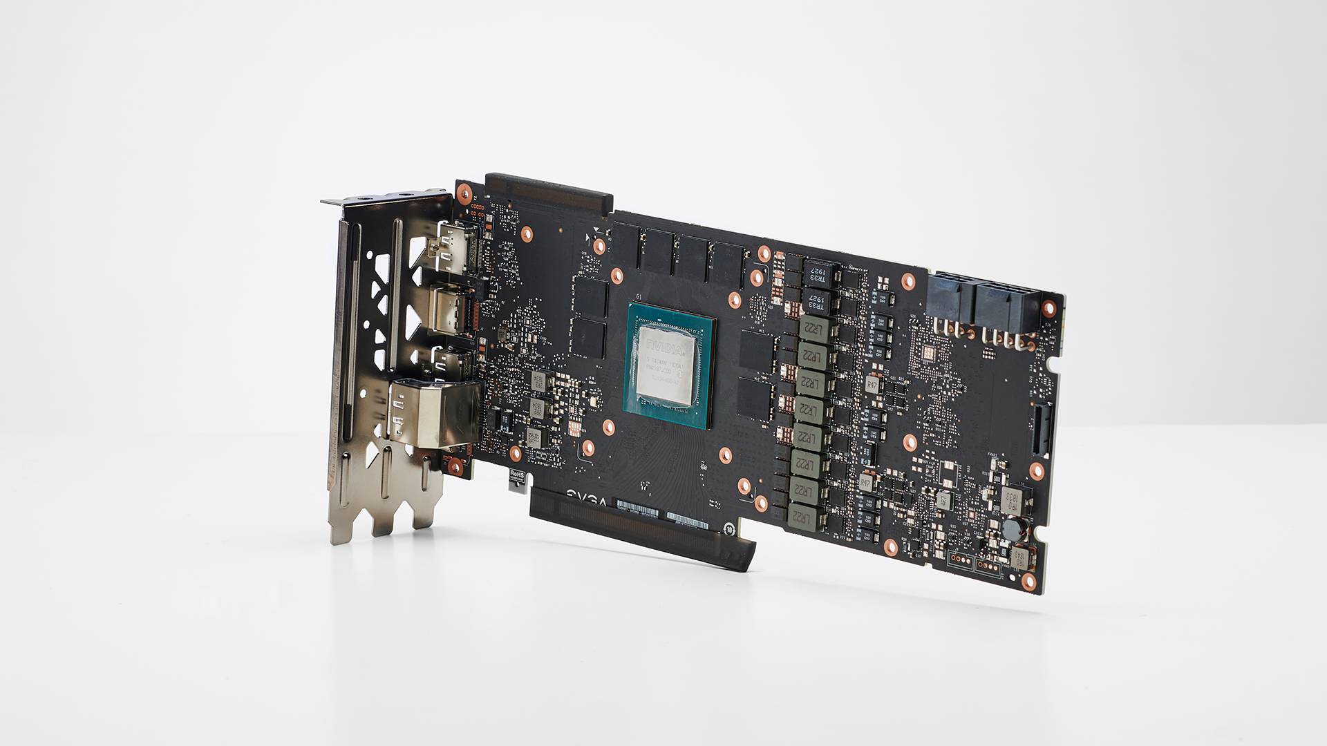
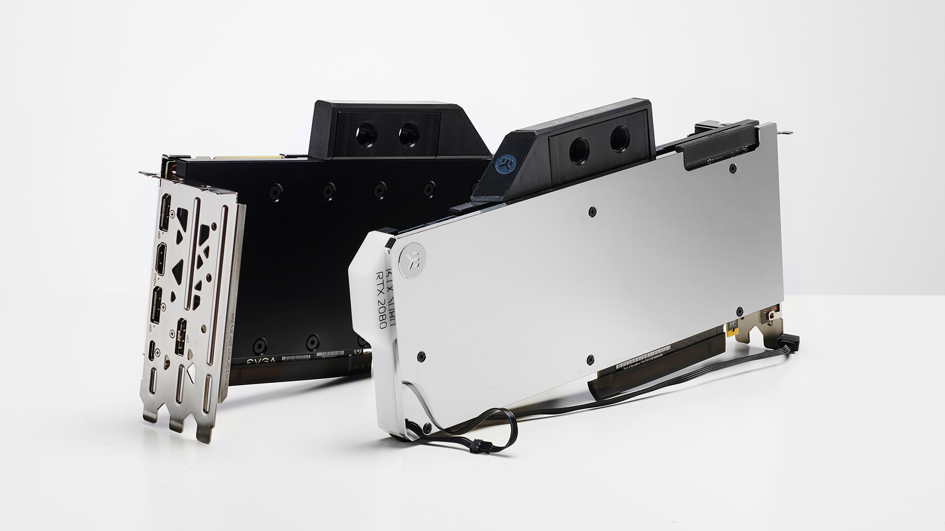
The most nerve-wracking part of any liquid-cooled build is stripping down your $750 GPUs and attaching waterblocks and backplates too them. Fortunately for us, we could leave the 4mm hex socket screwdriver at home, as EVGA uses standard Phillips head screws to mount its coolers to the card itself.
There’s not a lot to be said when it comes to stripping down graphics cards. You’ll often find if you’re buying a waterblock for an aftermarket card with a custom PCB they’ll come with disassembly instructions. However for reference PCB cards where one block will cover multiple GPUs you’re often on your own.
Your best bet is to remove all the screws from the back plate, and some from the rear I/O, and carefully pry the card away from the cooler, being sure to detach any cables in the process. Use your eyes and look for any points of tension where a rogue screw might be hiding holding the thing together. Once that’s out of the way, clean the GPU, apply new thermal pads, new thermal paste, and carefully seat the waterblock on the card. Follow the instructions, and if you’re attaching a backplate afterwards, read the instructions for that too before you begin, as you’ll need to install less screws with the waterblock, than what the waterblock manual will tell you.
2 - CPU Block
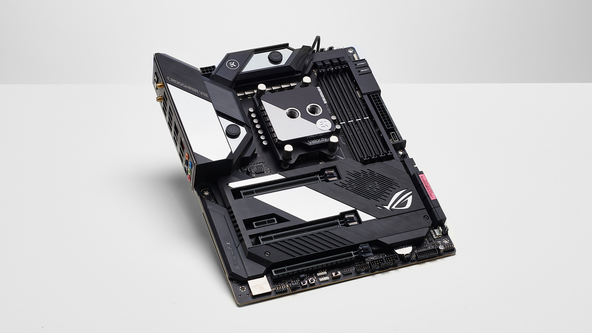
Our Velocity Strike CPU block came as standard in its Intel setup. Rather bizarrely however there’s no instruction manuals anywhere on how to convert it to its AMD mounting plate, not in the box, or on the website.
To do this, you’re going to have to remove the four 2.5mm allen screws at the bottom of the contact plate, carefully remove the copper plate, the mounting plate, the gasket and the JET plate and replace them all in the correct orientation with the new AMD mounting bracket where the Intel bracket was. Keep a careful eye on the orientation of your RGB lighting, and the direction your JET plate is facing, as if you get the latter wrong, it’ll spell catastrophe for your loop reducing coolant flow dramatically.
Once we finished off swapping out our mounting plate, we installed our Ryzen 9 3900X into the Crosshair VIII Formula, applied some Noctua NT-H2 thermal paste and secured it in to position. We love how the mirrored finish on the EK block matches up with the styling on the Formula. If you’re not a fan however, EK also sells a completely mirrored block, or the same one as pictured above but with the mirrored and acetal sides reversed.
3 - Dummy Fitting
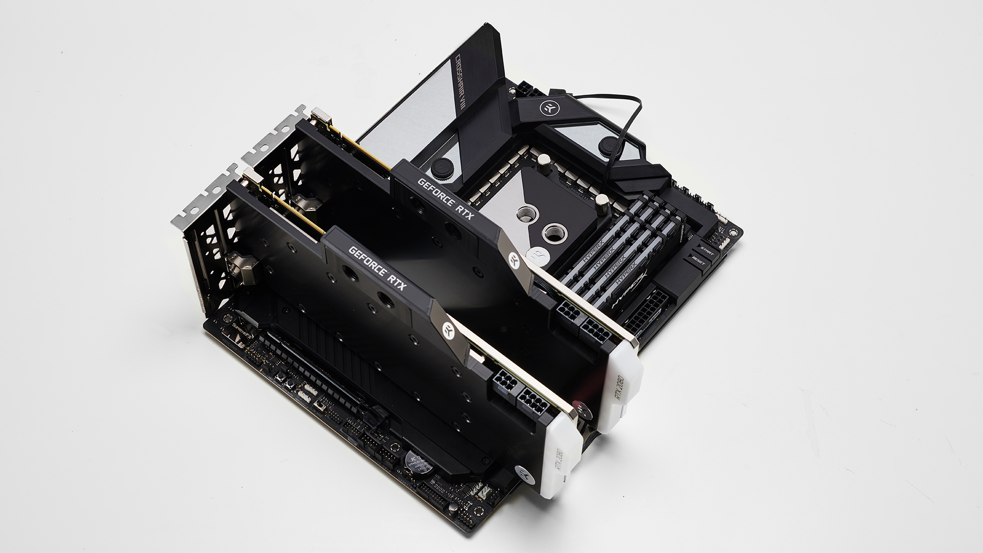
With that out of the way, we took the opportunity to do a dummy installation run to give us a heads up on how things would fit and where our tubing runs would need to be once the motherboard was installed. With the memory and the GPUs in place, it gave us a better grasp of how we’d have to handle the cable management, and when we should install the M.2 PCIe drives.
Get Tom's Hardware's best news and in-depth reviews, straight to your inbox.
4 - PCIe Installation
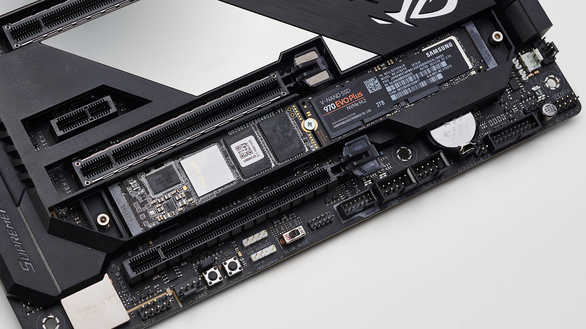
To start installing the PCIe drives we needed to remove the bottom most heatsink from the motherboard. Two small Phillips head screws secure it at both ends. Once removed it’ll simply pull off from the bottom right corner. Inside there’s a single small Phillips screw in the middle and a standoff with an M.2 slot at either end. Remove the screw, slot both of your drives into position, carefully place them down, resecure them with the screw, pull the film off the Laird thermal pads underneath the heatsink, and resecure the heatsink back into position.
Getting the Corsair MP600 drive out of its housing can be tricky. To do that, there’s two small tabs that need to be pressed down on either side of the heatsink. Once they were pressed in, we were able to lift the top of the heatsink off the SSD, and slide the drive out ready for installation in the motherboard.
5 - First Install
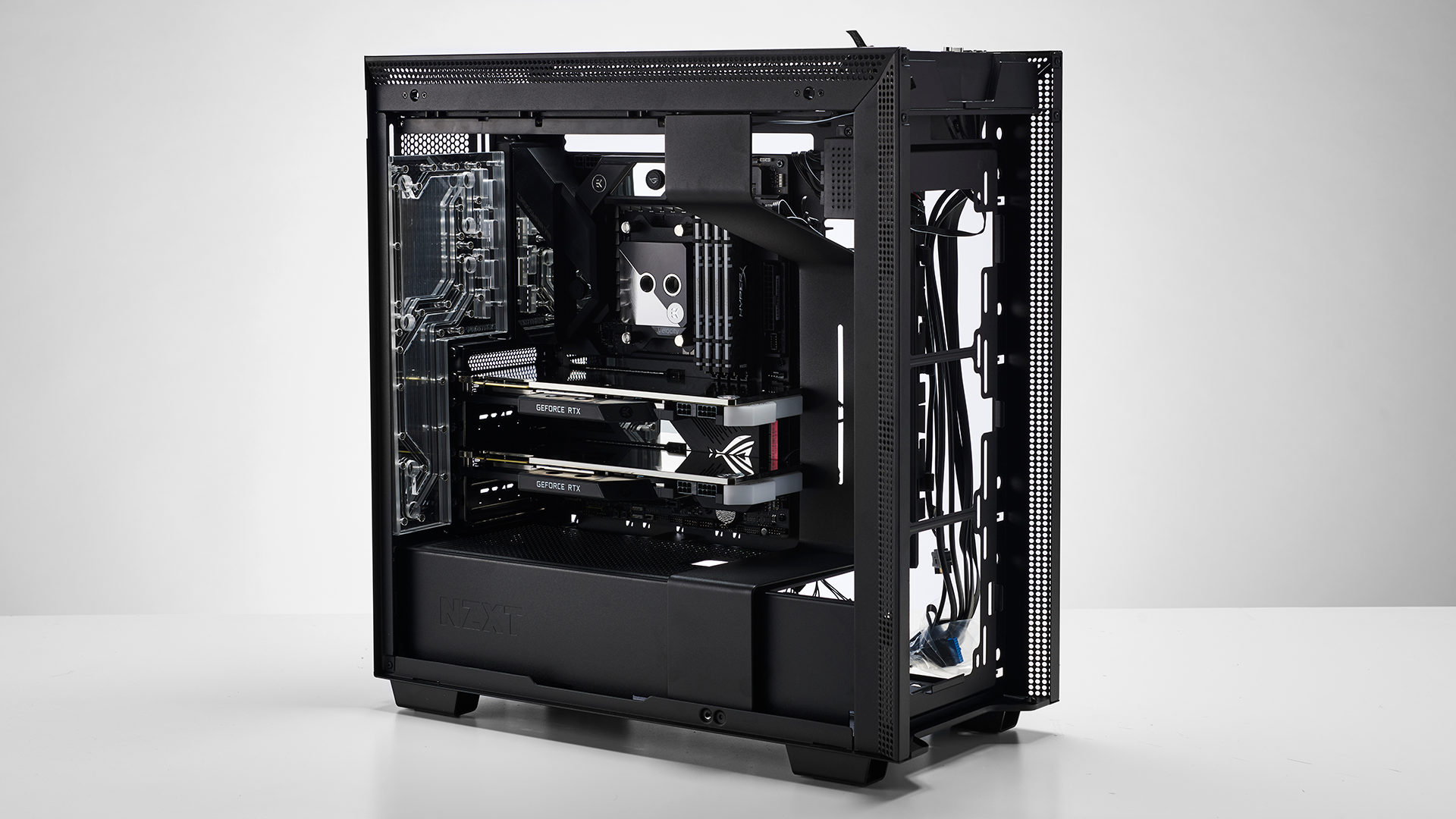
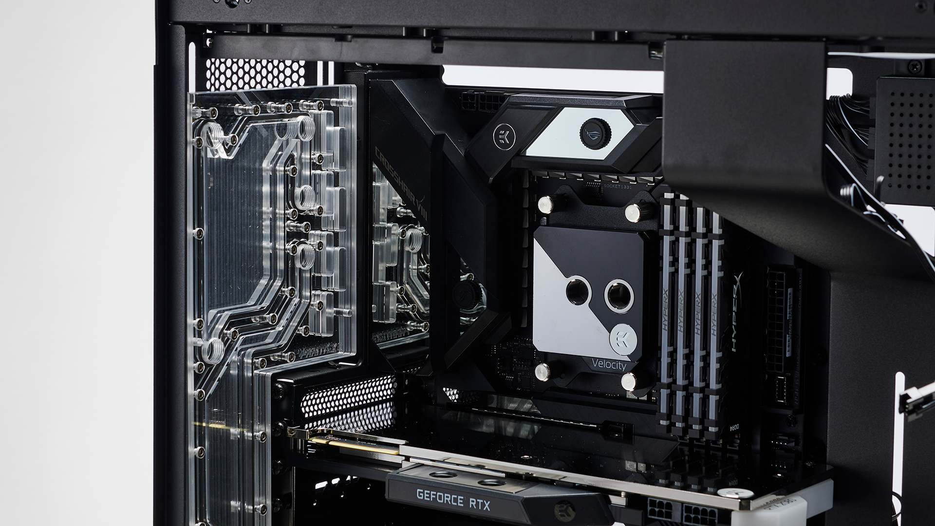
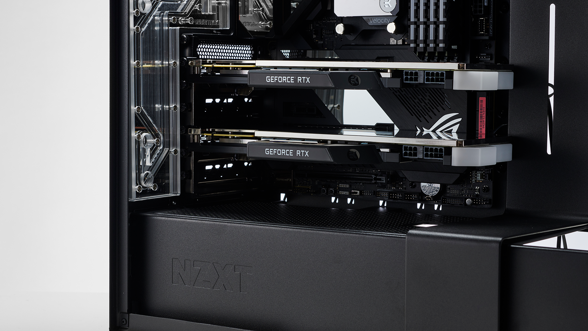
So here we have the first look at our system inside the chassis. We’ve installed the motherboard, secured the graphics cards, popped the memory in, and installed the Phanteks distribution plate in the rear. One thing to note with the distro plate is that you will need to install your graphics cards before installing it, as once the plate is in position you lose access to the screws holding the GPUs in.
Our original intention for this build (and thus why we requested two different sized reservoirs), was to run a horizontal reservoir below the second GPU, connecting up between the distribution plate and the pump. As you can see, however, there’s just not enough clearance below the GPU to allow that to happen, so we knew here that we’d need an alternative solution.
6 - Top Radiator Install
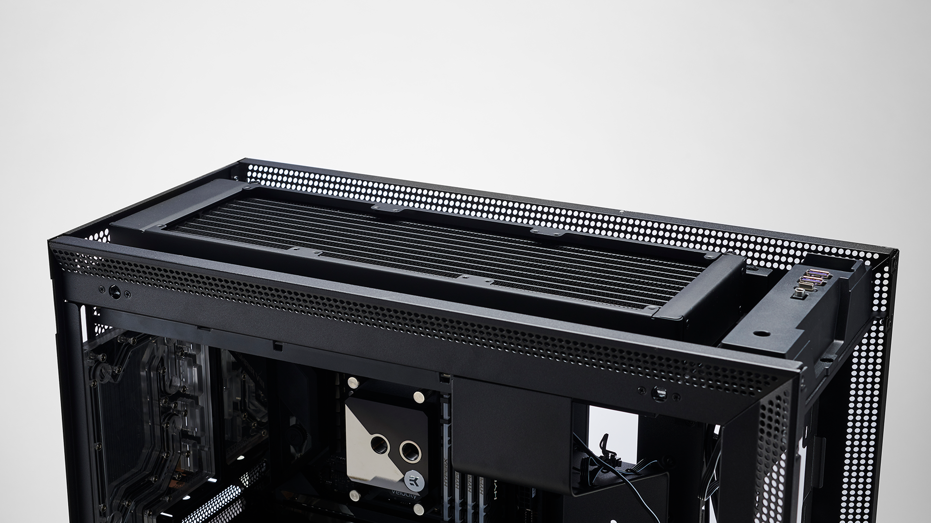
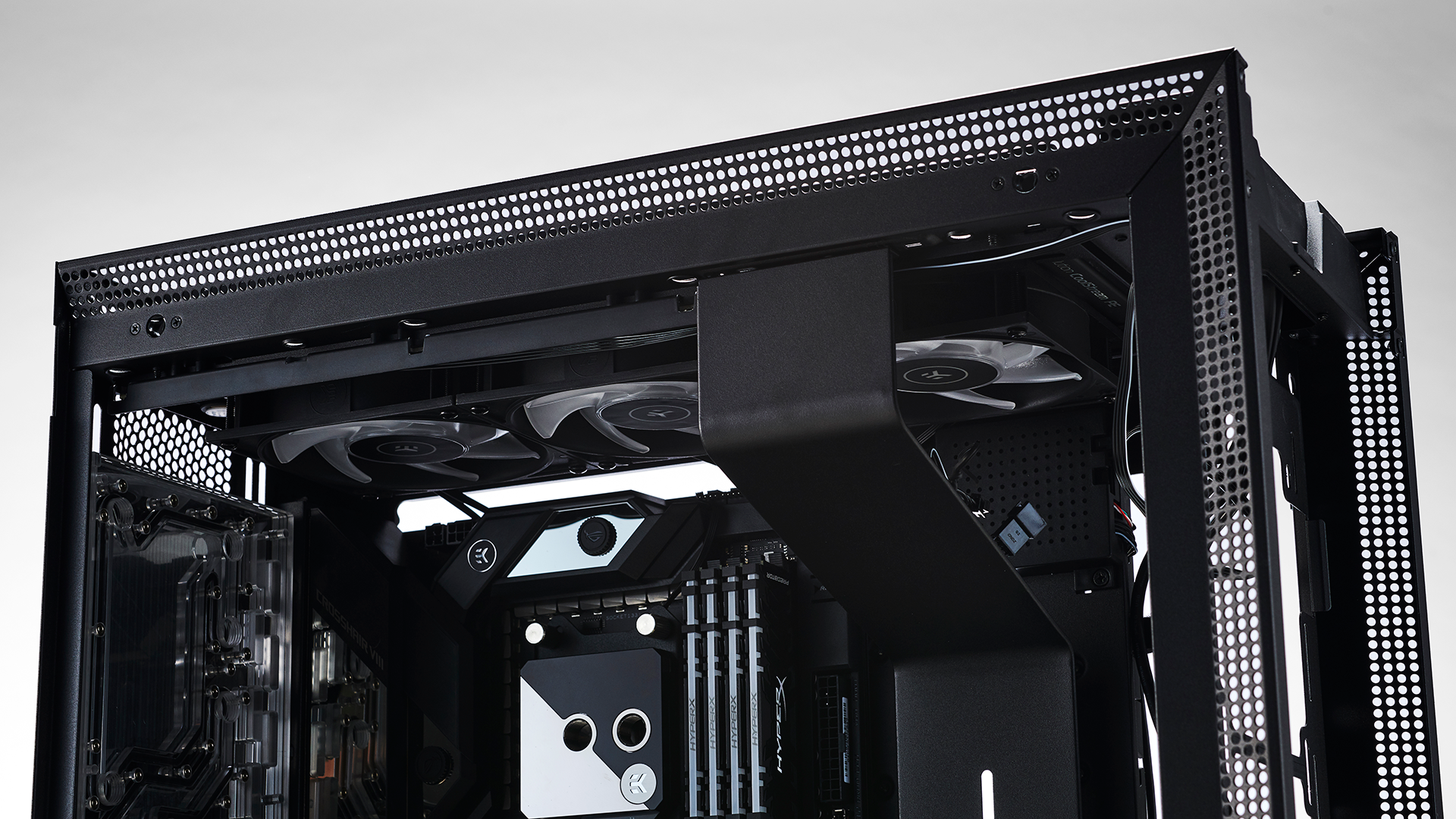
At this point,we decided to install the uppermost radiator to see how the build would come together. We wanted to run a 360mm PE EK rad in the roof with the fans in the interior. However as you may notice, here the radiator is way too tall to gain access to the ventilation. What’s worse than that is that it’s also conflicting with the top most panel. In hindsight we should’ve checked before ordering the parts in, and instead opted for a slim edition radiator (similar in thickness to those commonly found in AIOs). However we’ve got a solution in the works for this one which you’ll see a little later on.
We couldn’t just swap the orientations round and have the fans in the roof, because the rad is so thick that it comes into direct contact with the motherboard and the top of the front radiator.
7 - Front Radiator Install
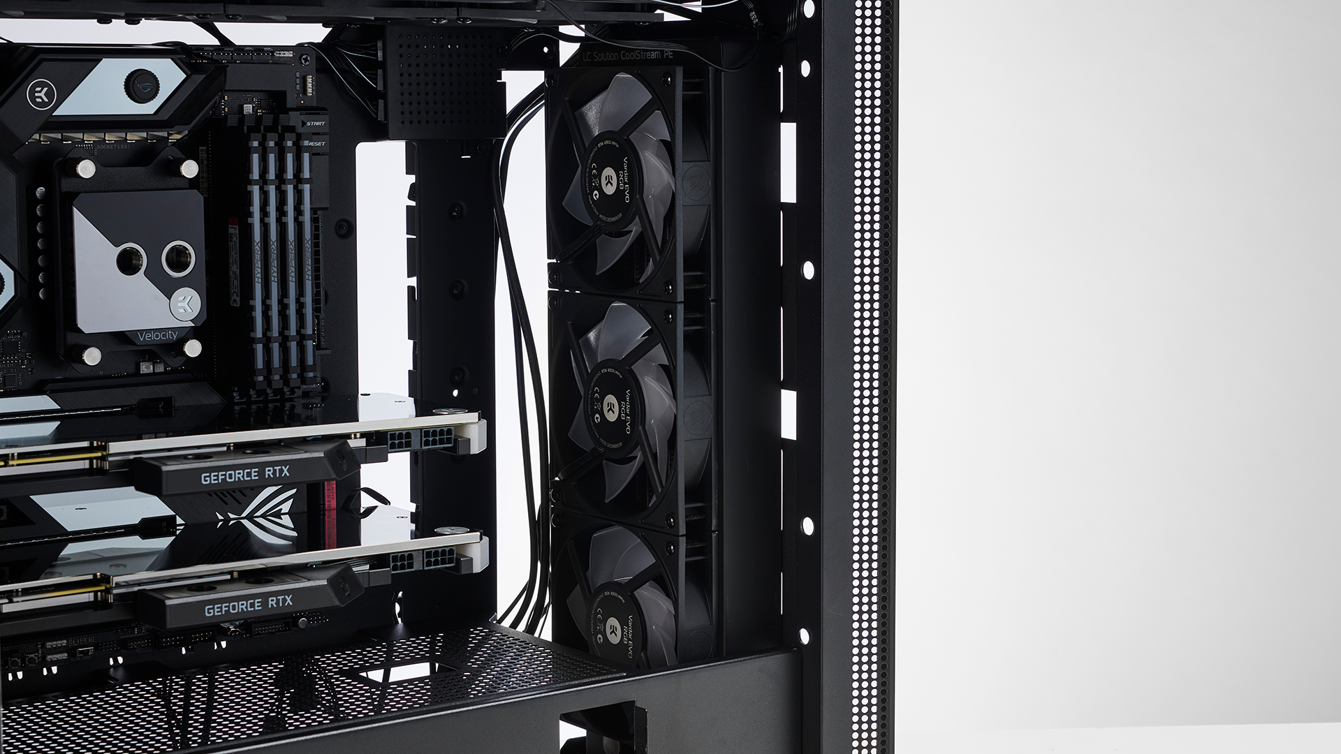
With our front radiator, we also sorta hit a similar frustration, albeit for different reasons. At this point, we’re already thinking about where our tubing runs are going to go, and we know we need to connect our front rad to the roof rad. If we place the three 120mm fans in front, the ports on the bottom of the front radiator are way too far forward to provide us with easy clean lines to make it to the roof, and so, we decided this was the best orientation.
It’s not the end of the world, and the extra lighting internally will be a boon to have, even if it means we have to run our front 3 fans at a higher RPM to offset the net effect of airflow impedance.
8 - Rear I/O of dreams
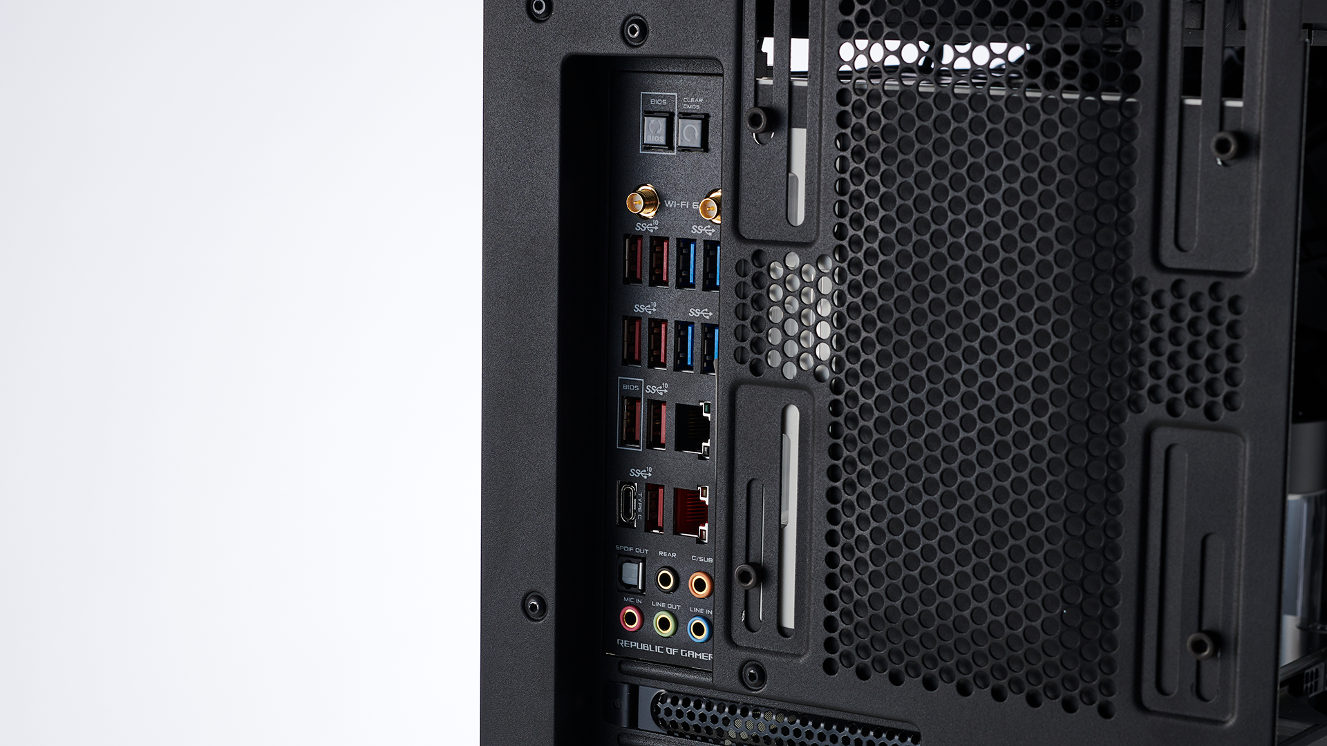
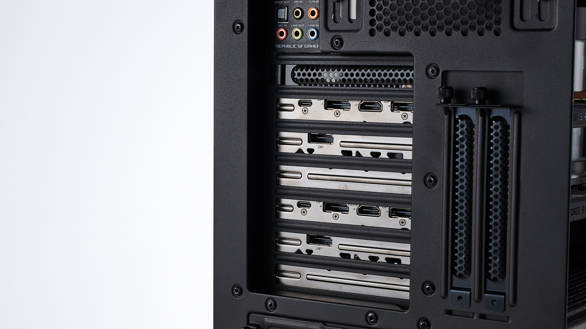
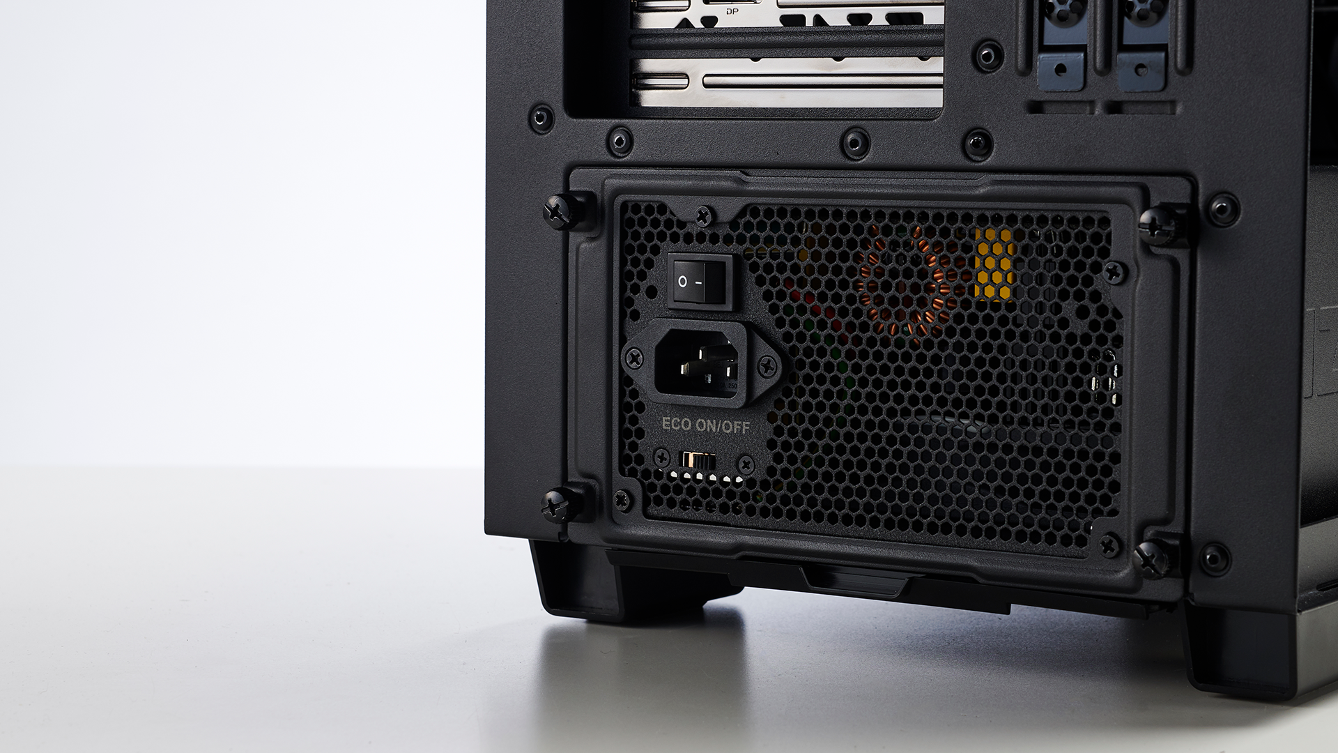
There’s a lot going on here, but the most obvious of which is just an appreciation for how much I/O we’re going to get with this system. 8 USB ports, two ethernet ports (one of which is a 5 Gigabit port), audio out, WiFi AX, Clear CMOS and BIOS reset buttons, six DisplayPorts, two HDMI ports and two USB Type C DisplayPorts as well.
You can also see here how our distribution plate is mounted to the rear of the chassis. Four allen screws hold it in position along the same rails as the 140mm fan would sit, meaning you can adjust it and move it up and down dependent on port orientation, something we’ll aggressively take advantage of later on.
9 - Reservoir Placement
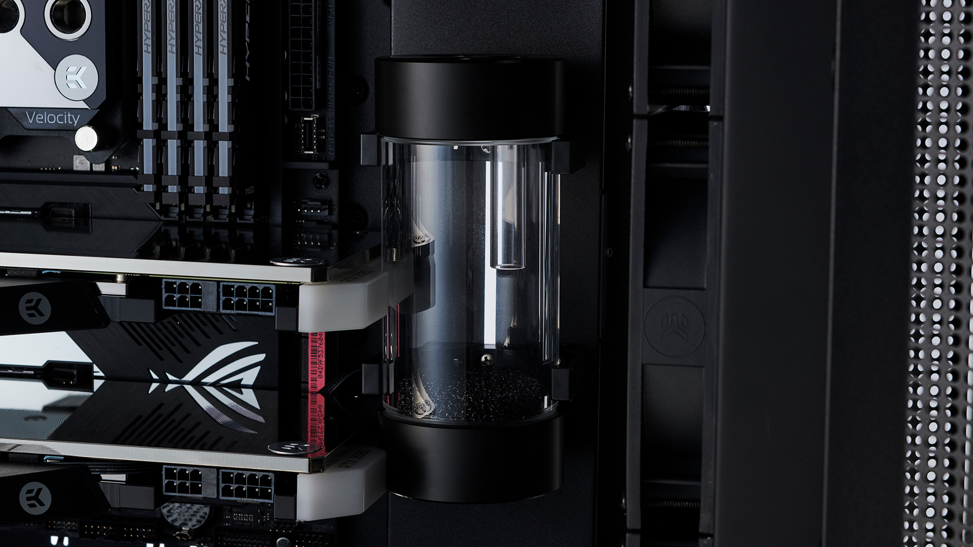
As we mentioned earlier, reservoir placement in this build was somewhat problematic. Now, theoretically the distribution plate itself can act as an additional reservoir. However, for the sake of hiding our pump, we also wanted to include another reservoir closer to it with a gravity fed connection. What we’ve done is mount our 150mm reservoir directly onto the cable bar in the H710i’s interior.
The EK-RES X3 comes with mounting brackets included as standard. To install the reservoir brackets, we removed the cable bar from the chassis, then mounted the brackets by threading the Phillips screw through it and secured it on the other side with a small nut (also included). We then reinstalled the bar back into the case, and moved the reservoir mounts to the position we needed them to be (bearing in mind the clearance of the GPU). Then with a bit of force simply pushed the reservoir into the brackets. The brackets are fairly flexible and will “snap” on, securing the reservoir into position. It’s definitely a tight fit, and slightly nerve-wracking installing it past those two lumps of RGB at the end of the GPU blocks, but it all worked out in the end.
10 - Cable Time
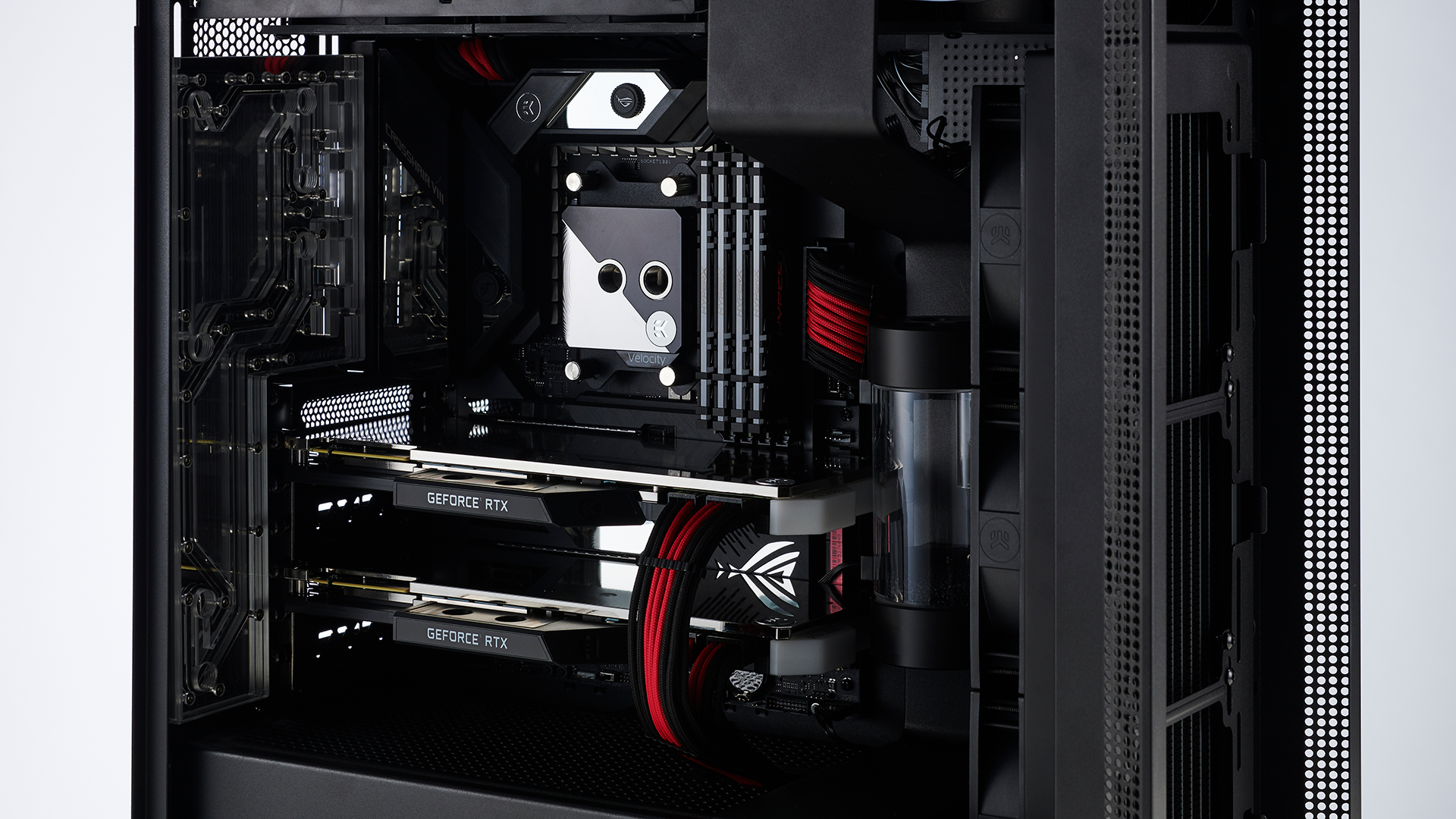
Before things get too messy with tubing runs and pumps, we decided to install the cables. The NZXT H710i comes with a small front panel I/O block (similar in appearance to a USB 2.0 header), that you simply push into the front I/O on the board. This stops you having to worry about what pin goes where, however not all boards support the traditional I/O pin layout (looking at you Gigabyte), so you do have to use an included splitter/adapter if you do go that route.
11 - Pump Mounting
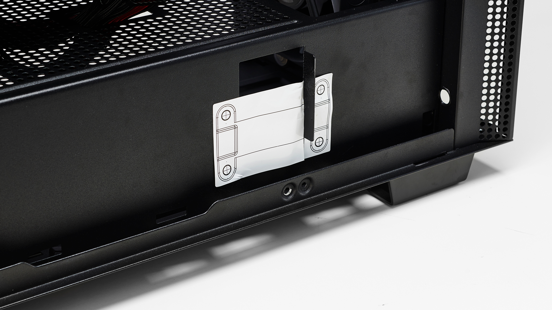
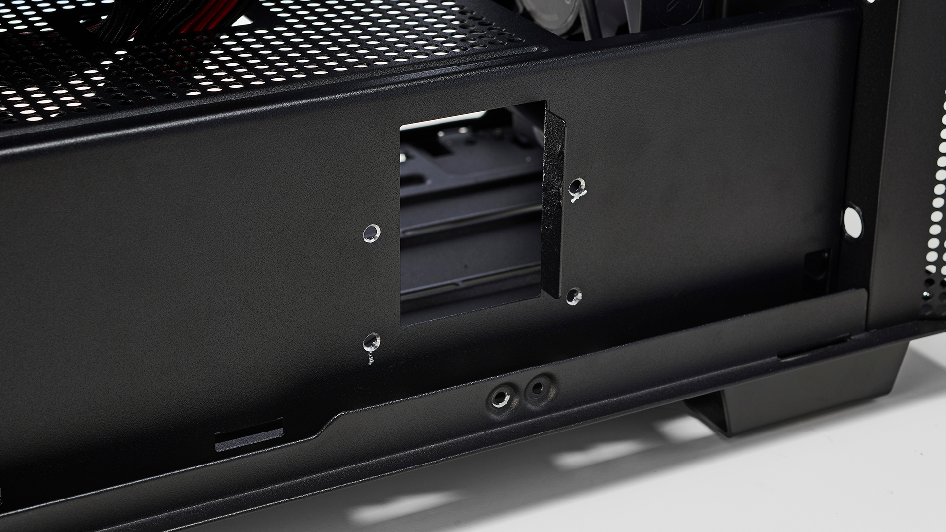
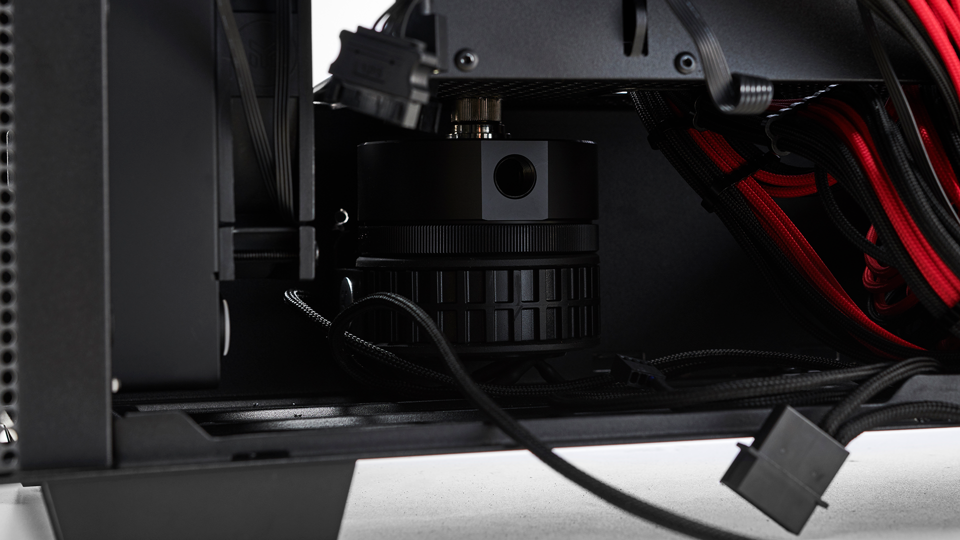
Now on to the pump. We’ve removed the cable bar and reservoir once again for this. EK’s Revo D5 pump can be mounted in a few orientations, however if we were to mount it directly into the floor of the chassis, the inlet would be located in the middle, and the outlet in the roof. That’s less than ideal, so instead we’ve opted to drill four holes in the side of PSU cover behind where the cable bar will be mounted and install the pump there instead. This means our inlet will be at the top (closer to our reservoir), and the outlet will be in the middle instead, and next to our radiator. To do this we used EK’s included sticker guide for drilling mounting points.
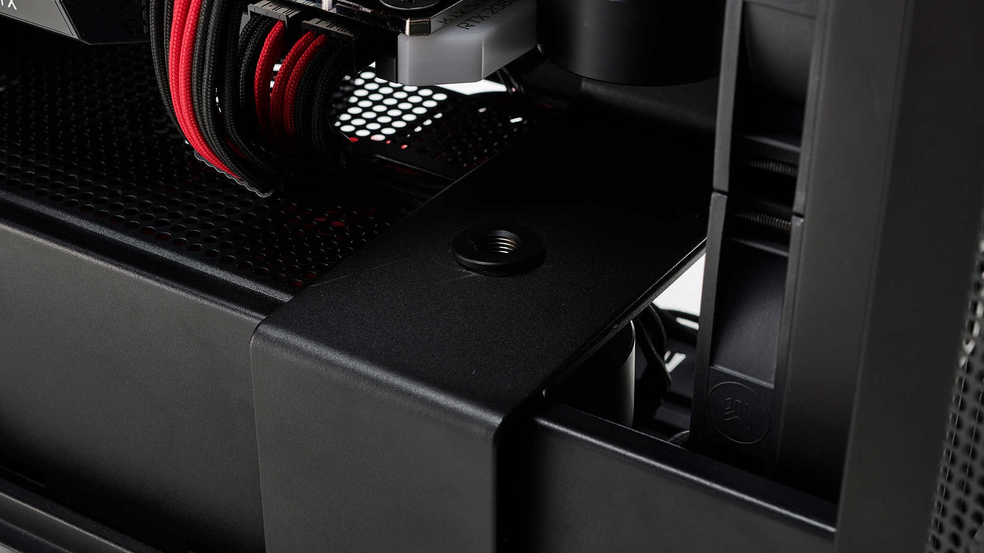
Once that was done, we needed to find a way of connecting the reservoir to the pump. Here we took advantage of a G1/4-inch passthrough fitting and drilled straight down through the cable bar, and through the PSU cover.
Similar to how we drilled these holes with the pump (and because we have so much electrical hardware already installed), we masked off the area with tape, and paper towels to stop shards of metal going everywhere, then used a drill bit to drill a large enough hole through the cable bar and the PSU cover. Once that was complete, we used a male to male fitting to connect the pump to the G1/4-inch passthrough, then secured it to our case using the holes we’d drilled earlier on the PSU cover behind the cable bar.
12 - Installing Fittings
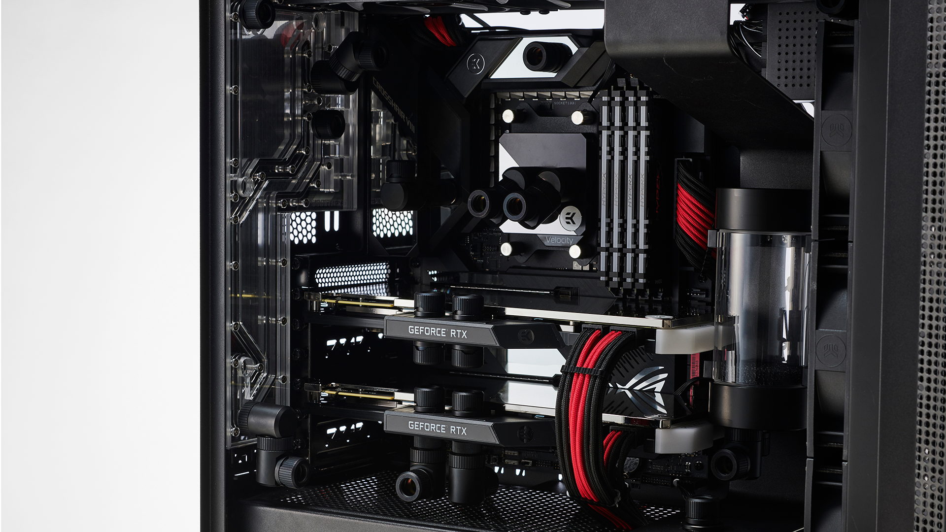
Now that all of our liquid-cooling hardware is in position and all necessary cables are in place it’s time to focus on the fittings and tubing runs. First thing we do is throw the fittings we think we’ll need in position to get an idea of where things might go.
We’ve also adjusted the height of our distribution plate to compensate as well. It’s often a good idea when building a liquid-cooled rig to sometimes leave a problem for one day and sleep on it. Our loop plans on the second day of our build were far different from the day before, and ultimately superior and easier to pull off. Time is your friend when building a completely new system like this. In fact, even this configuration seen in the picture above is far different to the end product.
13 - Tubing Runs
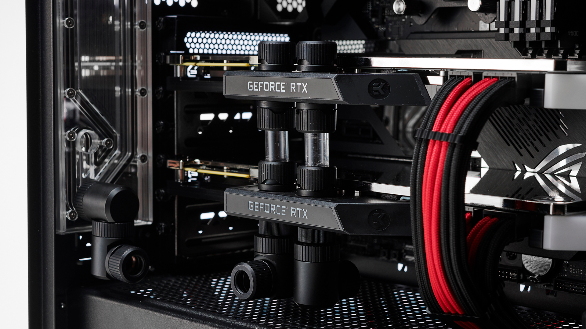
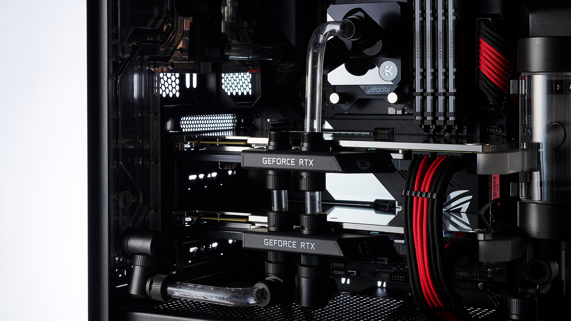
And so begins our tubing runs. We always start out with what appears to be the easiest tubing runs to do, that’s the straight ones. Ironically, getting the lengths correct on the two connecting a GPU in parallel can be quite challenging. The other straight tubing run we found easy to complete was the one connecting the front radiator to the roof radiator. Simply cut it down to size, install your fitting cap, and secure in position with the help of a few angled fittings and extensions, no bends required.
Once that was out of the way, we began to work on some of the simpler 90 degree bends. The one connecting the top radiator to the distribution plate, the two connecting the distribution plate to the VRM block, and a final one connecting the GPUs to the distro plate at the bottom.
90 degree bends are typically the easiest bend to create, and in fact it’s one of the cleanest looking bends too. If you can, we recommend all of your bends should be simple 90s compensated with rotary and angled fittings, and extensions to get them in the correct position. The more bends you add to a length of tubing, the more difficult it becomes to create, and the messier it can look.
14 - CPU Layout
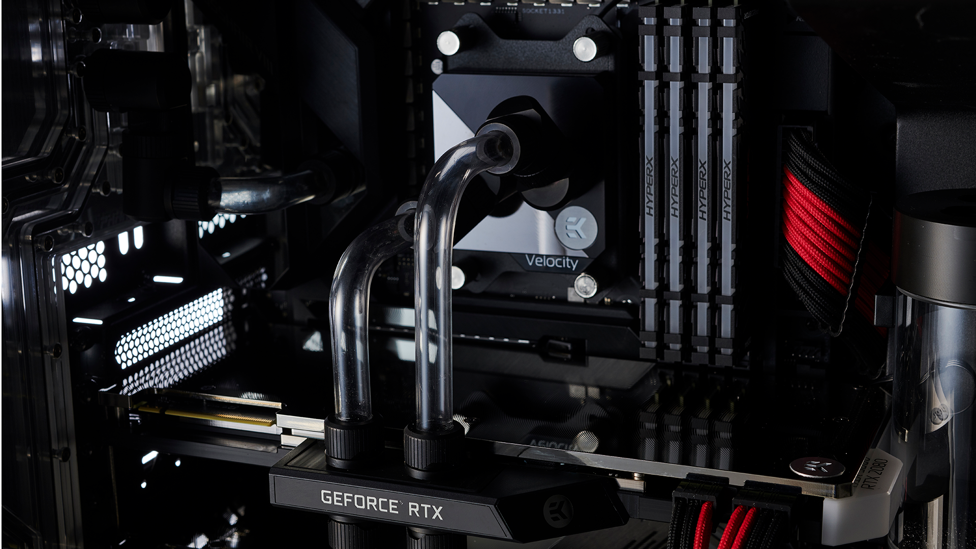
Now we know this is going to be the biggest point of contention for our loop amongst the liquid-cooling aficionados out there. Yep, we’re running a completely parallel CPU loop on top of our GPUs, aside from being a magnet for air bubbles, without a high enough flow-rate, it could theoretically cause trouble in regards to thermal performance.
As you can see from the photography in the step prior to this, we were already trying to suss out the best way of running the two tubes to the CPU. The problem is that, due to the size of the angled fittings (we’re using two 45 degree fittings together to create a more adaptable snakehead style 90 degree fitting), they actually come into contact with one another if we try and keep the lengths of tubing going to the CPU straight. In fact, to get them to align correctly we put them in this stepped setup, with the one on the left being lower than the one on the right. After we sussed that out, it was a simple case of doing another two simple 90 degree bends and cutting them to size.
15 - Pump Tubing Solutions
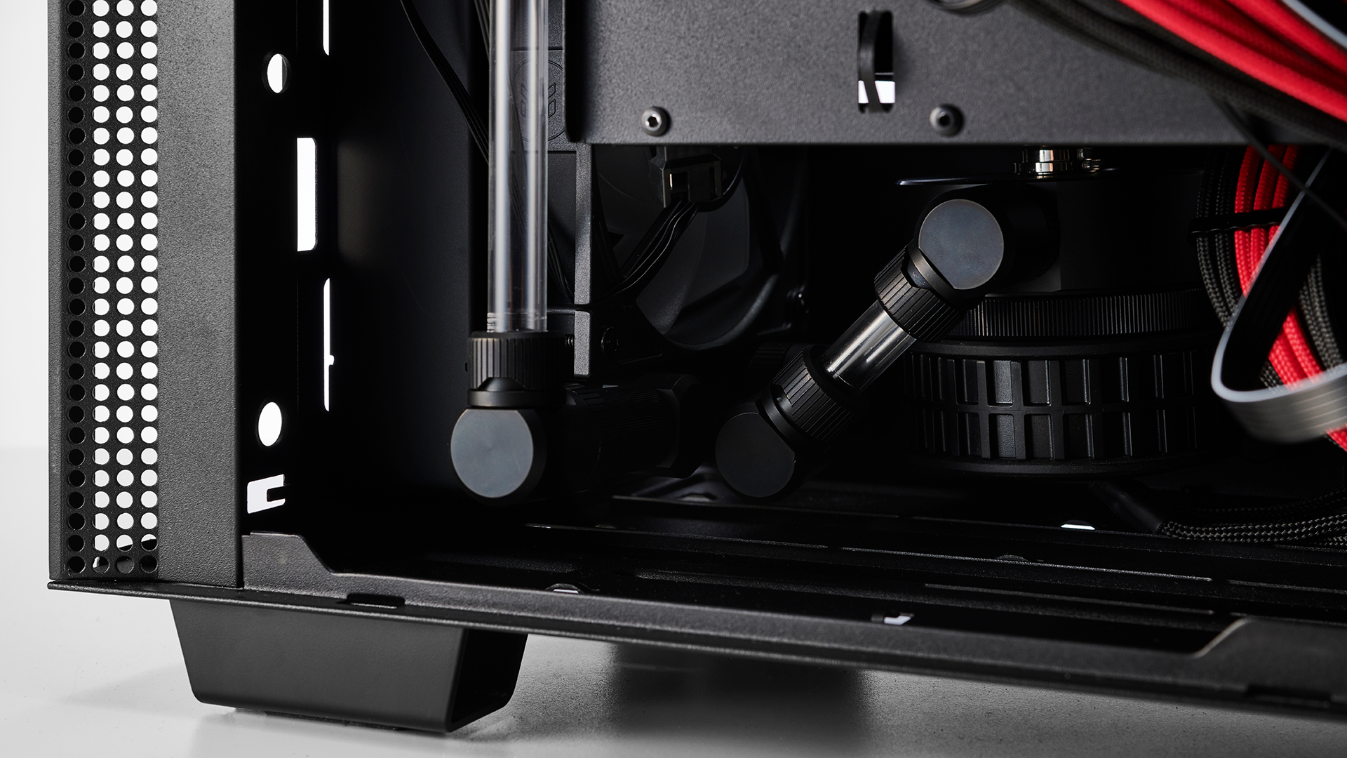
We were shocked at how easy it was to connect our pump to our front radiator. With the help of two 90 degree fittings and two extension fittings in between them on the radiator side, we could run a short straight length of tubing, between the rad and the pump itself. Then to connect the front rad to the top rad we used a similar solution, just at a different angle and with one less extender. Thanks to where we located the pump in this build, the radiator fittings fit perfectly without contacting one another.
16 - Reservoir Runs
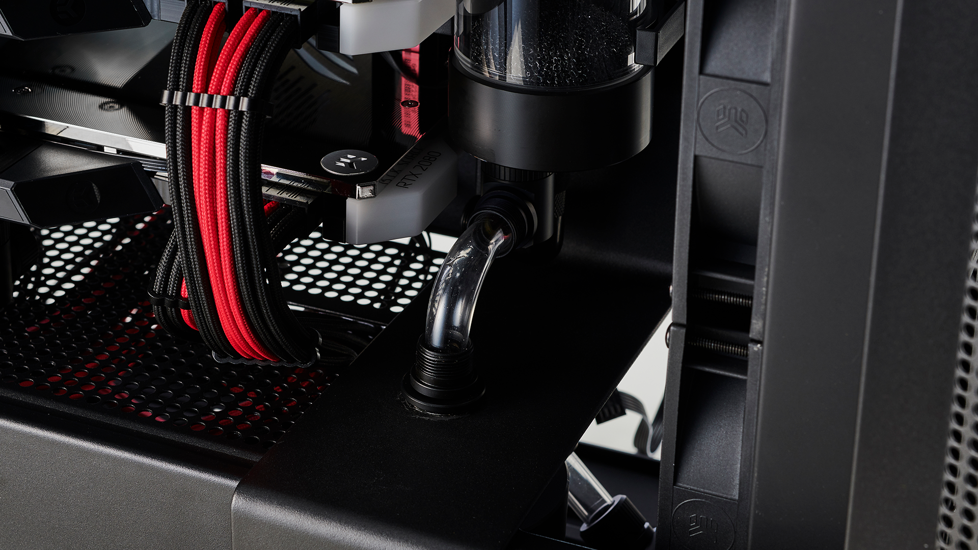
The last piece of the puzzle was how to connect our reservoir to the GPU and to the pump below. The former being the most difficult. Unfortunately again due to the size of EK’s latest Torque fittings, we couldn’t fit two angled fittings on the underside of the reservoir without them coming into conflict with one another. To get around it we had to lean on a single Alphacool 90 degree fitting hidden at the back of the reservoir, out of sight. Because it’s far smaller than the EK Torque fittings, it sits in their snuggly without a problem. You could use one of the older EK fittings to do a similar job. However we had spare Alphacool fittings to hand from previous builds.
Then, to connect the GPU to the reservoir, we bent a single 90 degree bend into a length of tubing, and ran it away from the bottom GPU, directly along the side of the motherboard, and into the reservoir before securing it in place. That last part is the hard part as it’s difficult to see and get your hands underneath the graphics card to tighten the compression caps.
With that out of the way, it was time to do our smallest 90 degree tubing run between the reservoir and the pump. The problem is that, when you put a bend in a length of tubing, the tubing tends to widen at the location of the bend ever so slightly, thus the closer you cut to that bend, the harder it becomes to put the compression fitting cap and o-ring on it without scraping or damaging the tube itself. The o-ring can become particularly troublesome, in fact we often have to push it on to the tube with a small screwdriver before fitting the tube and securing it with the compression cap.
17 - NVLink Woes
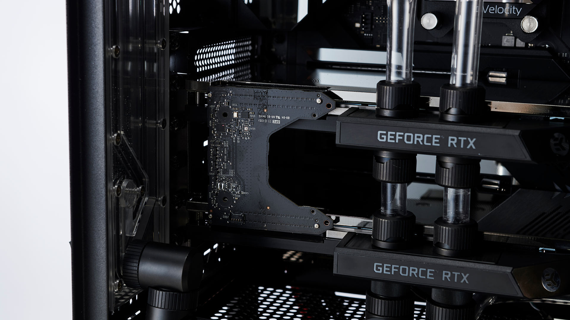
A common problem when it comes to running waterblocks on GPUs that you’re going to use in SLI is NVLink bridge compatibility. As these are designed to fit on cards that don’t have a massive inlet/outlet block on top, most SLI bridges have become glorified RGB totems, massive in scope and size despite the job they perform. The problem with that is they often contact the inlet/outlet area of a blocked up card, and in turn can’t be seated, a problem we found with our EVGA NVLink bridge. To get around this we had to disassemble the bridge itself.
There’s four Phillips head screws on the back of the bridge, remove these and you can then remove the top plastic cover that sits over the RGB LEDs. Underneath you’ll find two separate pieces of PCB. The uppermost one housing all of the lighting, is held in via clips located in four positions, a glue strip, and a small ribbon cable for the LEDs. Detach the cable, and carefully pry the RGB PCB off without touching the components on the board underneath. Then use a heatgun to remove as much of the glue as possible and you’re all set.
It’s a bit of a shame because we do love the look of EVGA’s NVLink bridge, but unfortunately needs must, and in a weird way the angled style of that black PCB still looks pretty snazzy.
18 - Cable Management
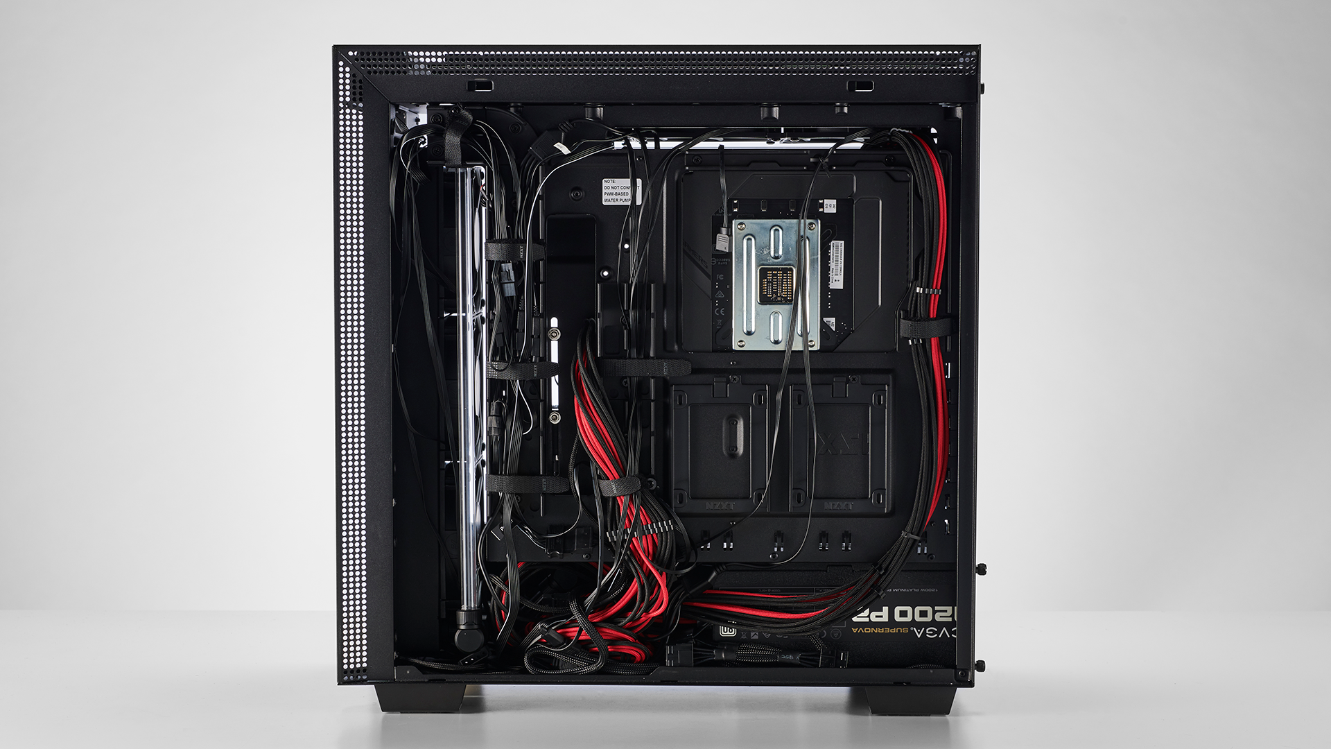
A quick peek at our cable management at the back of the rig, and you can see that it’s not as tidy as we’d like. Once all the RGB cables were in, we removed a few other unnecessary cables here and there. Most of the front I/O, the RGB light strips that NZXT have pre-installed into the case itself on the back of the cable bar and the top, and one length of fan headers coming from NZXT’s CAM fan controller.
At this point in time, we’ve also left the pump unplugged from both the motherboard with its fan header and it’s molex power adapter too. Fortunately the NZXT H710i has a push panel as opposed to a sliding rear panel. It works by slotting it into grooves in the bottom, then pushing and locking into place on top of the case making it far easier to secure the rear side panel and get those cables into position.
19 - Filling Time
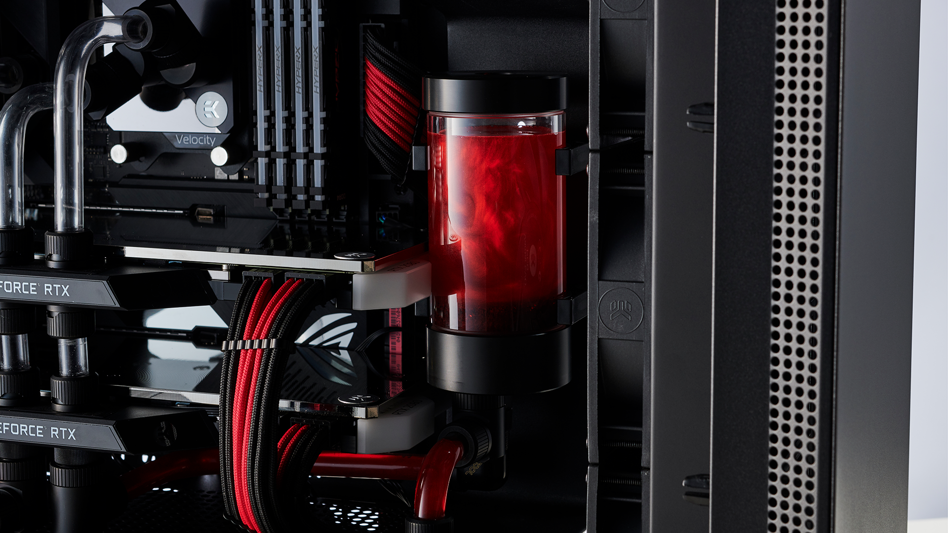
And finally we get to the filling part of our long journey. We’re using a mixture of Mayhem’s Aurora Red concentrate with some Ultra Pure H2O, and a couple of drops of Mayhem’s Silver Aurora Booster for the photography (it will be swapped out later for something a little more performance oriented). On filling our loop, we also noticed that the top of the reservoir was too tall to fit an angled fitting onto it, so, as we had a spare reservoir top, we swapped it over to the light version instead as it’s skinnier and allows us to fit a 90 degree fitting on top and a plug to help the filling process. It’s also something we’ll be leaving on until we’ve entirely bled the system of air, as it makes it far easier to fill it.
During filling, we actually use a spare PSU, with only a 24-pin cable with a bridged adapter, and a molex cable on it. This way we can power just the pump, and nothing else, without necessarily unplugging every cable from the system.
20 - Building Complete
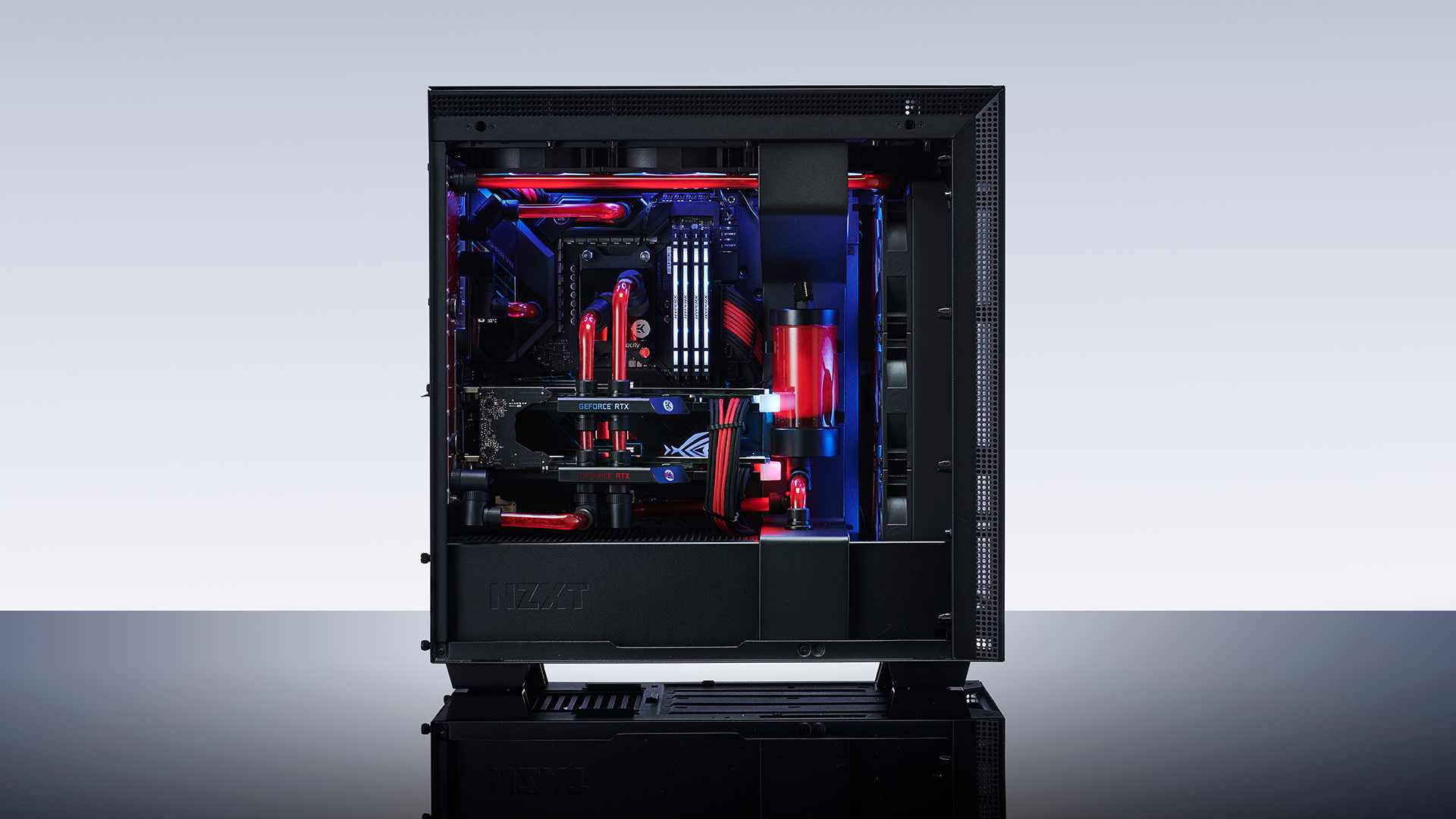
And there you have it folks, one complete liquid-cooled NZXT H710i, complete with Ryzen 9 3900X, twin EVGA GeForce RTX 2080 Supers, 32GB of DDR4 @ 3600 and a positive cornucopia of storage and liquid-cooling support. Is it perfect? Absolutely not.
So let’s point out where things could’ve gone better. From an aesthetic perspective, the biggest bug bear is that bottom left tubing run connecting the distro plate to the GPU, the angle on it is just frustrating, to get around this we have two options. First, as the 90 degree fitting connecting it to the distro plate is at an angle we could add a 10mm spacer in between it and the other 90 degree fitting, hopefully lowering the height of the fitting itself and the tubing run by doing so. Alternatively we could lower the distribution plate entirely to bring it in line, and then move the combo angled fittings at the top to compensate instead. The reason for the latter is that, with an extension fitting in between the two 90s at the bottom, it could potentially contact the glass side panel, stopping it from closing.
The last problem child as so far as tubing is concerned, is the bottom most VRM block to distribution plate fitting, there’s a bit too much pressure on it, and it’s being pushed ever so slightly backwards. Although it’s more aesthetically displeasing than anything else, over time it’s a potential leak hazard. To get around this we’d simply have to sand down the edge of that tubing run to reduce the pressure on the fitting, bringing it back in line.
The biggest performance problem by far however is the top radiator. Now we really ought to just swap it out for a slim-edition radiator instead, as in its stock configuration the PE just doesn’t fit. The top panel will not sit on it at all. To get around this, there’s actually a plastic layer attached to the top panel underneath with the push pins on it that secure it down to the case. We’ve removed that panel, as its secured only via Phillips screws, and cut it in half, as the conflict is at the rear end of the chassis (the radiator’s reservoir hitting the butt of the internal plastic sheet). Although it looks good for photography, as the panel is so close to the radiator, there’s zero airflow here.
The other solution outside of a straight swap to a skinnier rad, is to do something a bit more custom with the steel panel itself. In short, the best thing we can do is to take the panel to a machinist and have them cut out some ventilation from the top panel for that 360mm radiator, before having it resprayed. It’s a bit of a drastic step, but if you’re committed to that PE rad being in the roof, it’s the only solution.
MORE: Best Gaming Desktops
MORE: How To Build A PC
MORE: All PC Builds Content
Current page: Build Notes: Cool Runnings
Prev Page Building a Liquid-Cooled, Dual-GPU Gaming Rig Next Page What We Learned
As Associate Editor of Tom's Hardware's prestigous British division, Zak specializes in system building, case reviews and peripherals, and has a particular penchant for liquid-cooling. He's also a lover of all things Viking/Scandinavian (thus the poor attempt at a beard).
-
redgarl Is this an april fool joke? Dual GPUs is dead. I cannot believe I am saying that, but you are better just getting a 2080TI at this point. Be ready to wait a year for having decent drivers support for CF or SLI... if you get any at all.Reply
Anyway, really pointless article. -
djayjp "...using an Intel Core i9-9900KS may have given us a slight advantage in game due to its far superior single core IPC."Reply
No. Ryzen 3000 series has demonstrably higher IPC than this chip, but the Intel chip can have higher performance due to higher clocks. -
NightHawkRMX Reply
It depends. IPC varies much on what an application demands.djayjp said:No. Ryzen 3000 series has demonstrably higher IPC than this chip, but the Intel chip can have higher performance due to higher clocks.
AMD 3rd gen does have a superior IPC to 9th gen for programs like cinebench. You put a 3700x vs 9900k both at 4ghz, the 3700x will win cinebench.
However, a 9900k @4ghz will still outperform a 3700x@4ghz since Intel's gaming ipc is still superior. -
rugupiruvu why 2080TI inside “Silent But Deadly” got so bad results in 3dmark ?Reply
Worse than "Console killer" with RTX2080.
“Silent But Deadly” - TS - 9775, PR - 5967, FS U - 6801, FS - 22503
My 8600k + 2080 - TS - 10368, PR - 6690, FS U - 6548, FS - 22392 -
Blitz Hacker Reply
what your saying makes absolutely no sense at all. Instructions per Cycle/Clock is an averaged measurement, it's static on a cpu architecture. A measurement of the amount of work done, and it doesn't change dependent on core/clock speeds. If anything it's a base multiplier for the performance equation with the amount of useful work done per clock cycle. Speeding up the clock cycles doesn't make it do more work per cycle, it just makes it do more cycles faster. So saying the intel's gaming IPC is superior is a lie. Ryzen 3rd gen processors have been measured to have a marginally higher IPC vs Intel currently.NightHawkRMX said:It depends. IPC varies much on what an application demands.
AMD 3rd gen does have a superior IPC to 9th gen for programs like cinebench. You put a 3700x vs 9900k both at 4ghz, the 3700x will win cinebench.
However, a 9900k @4ghz will still outperform a 3700x@4ghz since Intel's gaming ipc is still superior.
As stated both ran at the same core speed the AMD will win, which is a result of a higher/better IPC. There is no differentiation of IPC based on 'gaming' 9900K(s) will run gaming better currently, with a lower IPC and a much higher clock speed making up for the IPC deficit -
Blitz Hacker yHvSKY8View: https://i.imgur.com/yHvSKY8.pngdid someone have a stroke at the end of the article about the memory, cause that wasn't really english and didn't make much sense at all 'Build and T??' What's a Theat?Reply