How to Use FreeCAD for 3D Printing
Design and prepare your 3D models for 3D printing using FreeCAD
FreeCAD is a free and open-source 3D modeling software ideal for designing and preparing your designs for 3D printing. It uses a parametric approach which enables you to make changes and dimensional accuracy on your designs. In this approach, the history of objects and their relationships to each other is recorded, allowing you to modify them at any stage of the design process easily. You can adjust parameters like dimensions, angles, and constraints while maintaining the structural integrity of your design. Additionally, FreeCAD allows you to create G-code directly from your designs. But before diving into these features, let’s explore the overview of the software.
Overview of FreeCAD
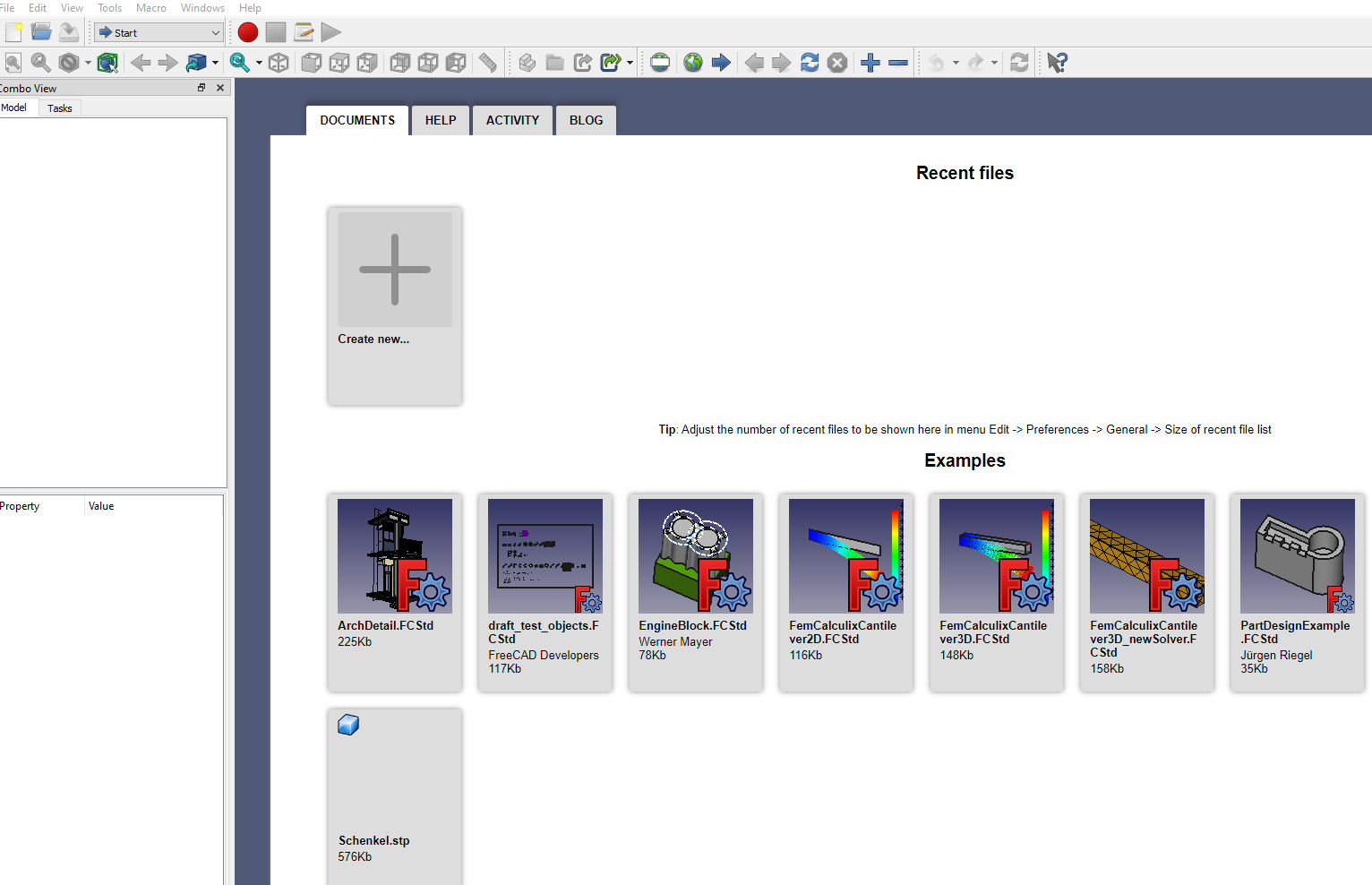
Go to the official FreeCAD website to download the software. It supports Windows, macOS, and Linux. You can choose the one for your operating system and then download and install it. After installation, you will see the interface shown below.
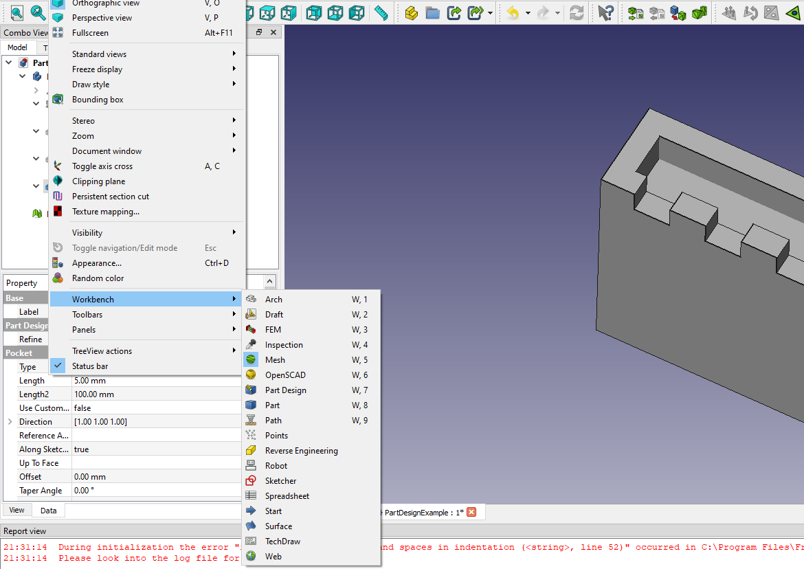
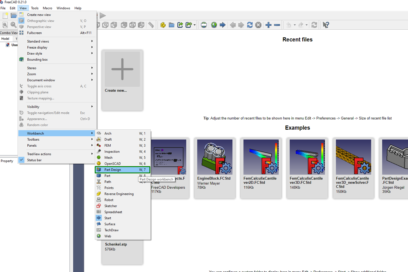
In the interface, you will see the menu bar and the tools section, just like what you would expect from standard software. What differs from FreeCAD is that it is organized into Workbenches, each providing a specialized set of tools for a particular task or workflow. There are workbenches specifically designed for part design, mesh editing, drafting, reverse engineering, and even architecture. You can find them from View > Workbench.
Each workbench typically comes with its own toolbar and menu settings; you can find them either at the top of the window or as side panels. We shall focus on the part design and mesh editing workbenches in this article, as they are the ones mostly used for 3D printing.
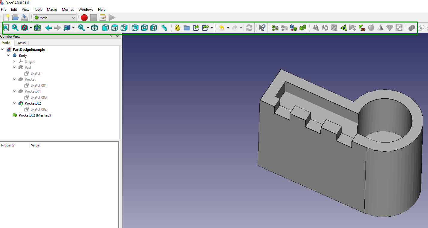
Menus for file operations, view controls, and general tools for modifying your designs are arranged along the top bar.
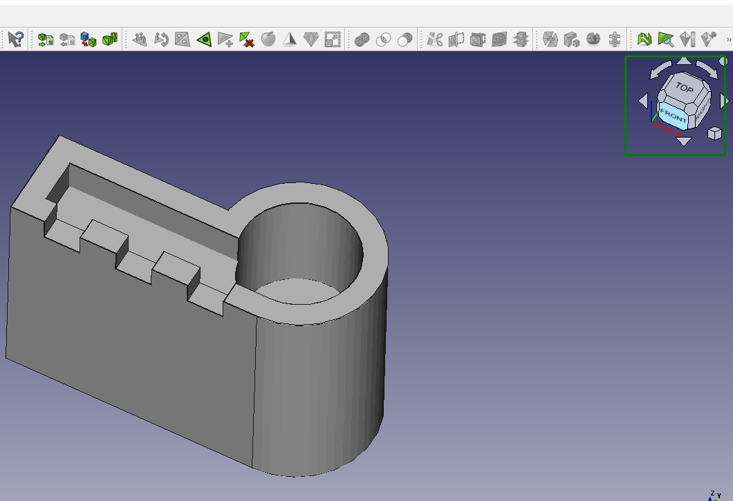
You can change the angle view of your design on the top-right section of the interface, as highlighted below.
Having looked at the overview of FreeCAD, let’s now have a look at how you can use it for 3D Printing.
Get Tom's Hardware's best news and in-depth reviews, straight to your inbox.
MORE: Best 3D Printers
Designing 3D Models in FreeCAD
For creating 3D models for 3D printing, there are various tools that you can use. One option is to switch to Part Design in the workbench section. As we mentioned above, this feature is great for designing solid models that are appropriate for 3D printing. It achieves this by combining 2D sketches, extrusions, and various modifications.
When 3D printing, you must ensure that your objects are designed as solid structures. Although they can have hollow interiors, you need to clearly define which areas are filled with material and which are not. The PartDesign Workbench is an ideal option as it automatically helps you maintain the solidity of your designs. You can find this option from View > Workbench > Part Design.
To use this option, you can follow the steps below:
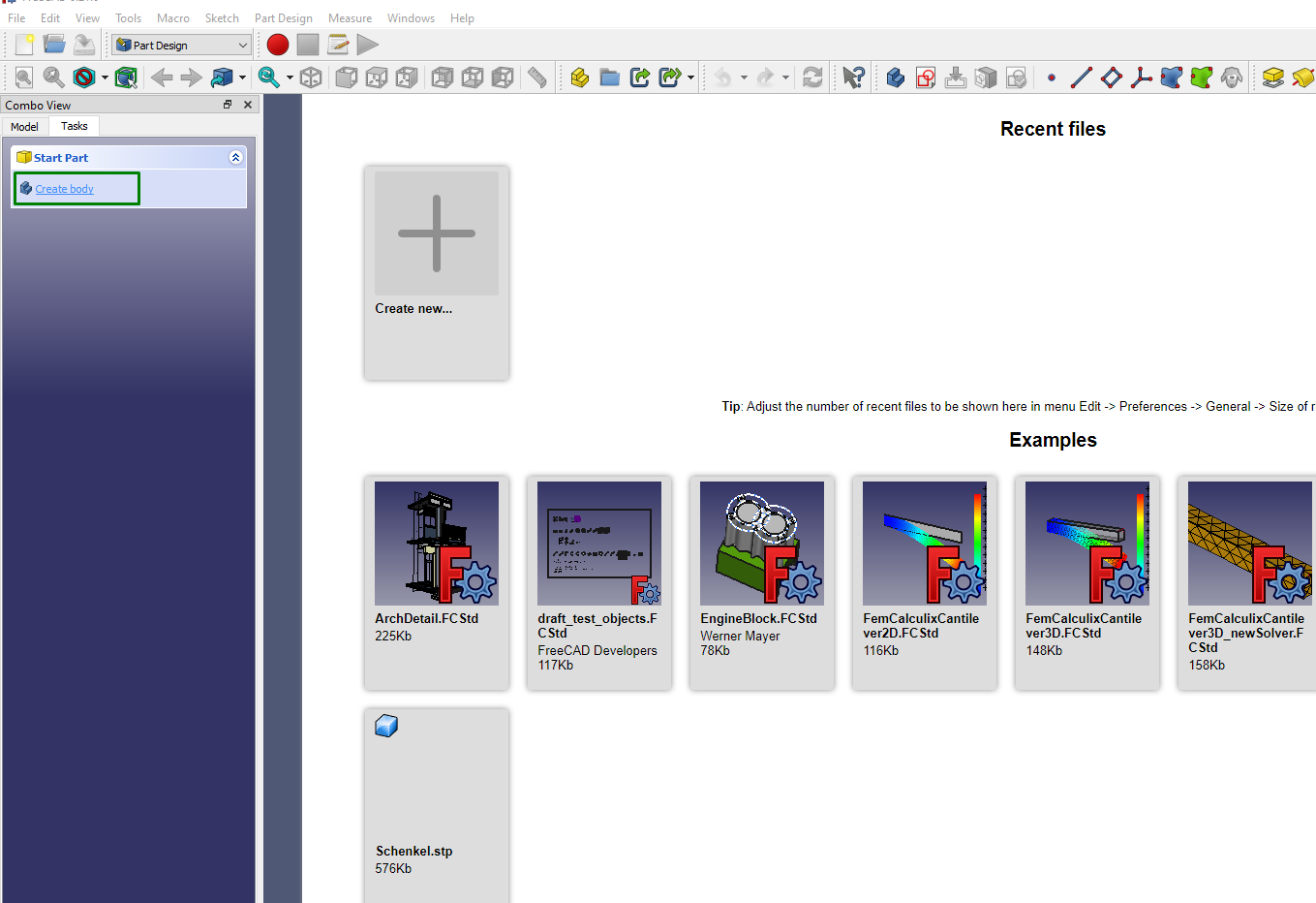
1. After selecting Part Design, you will see an option to create a body. Click on it.
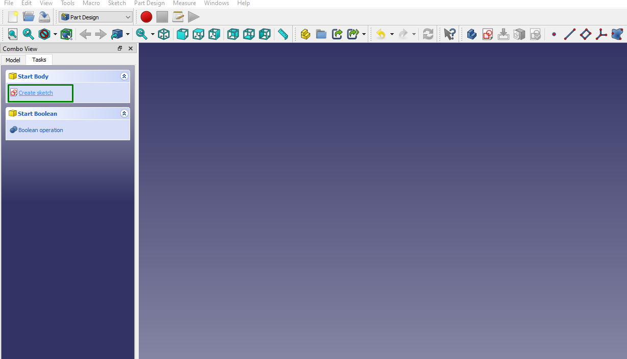
2. Click Create Sketch to create 2D sketches using lines, arcs, circles, and other sketching tools to serve as the building blocks for your 3D model.
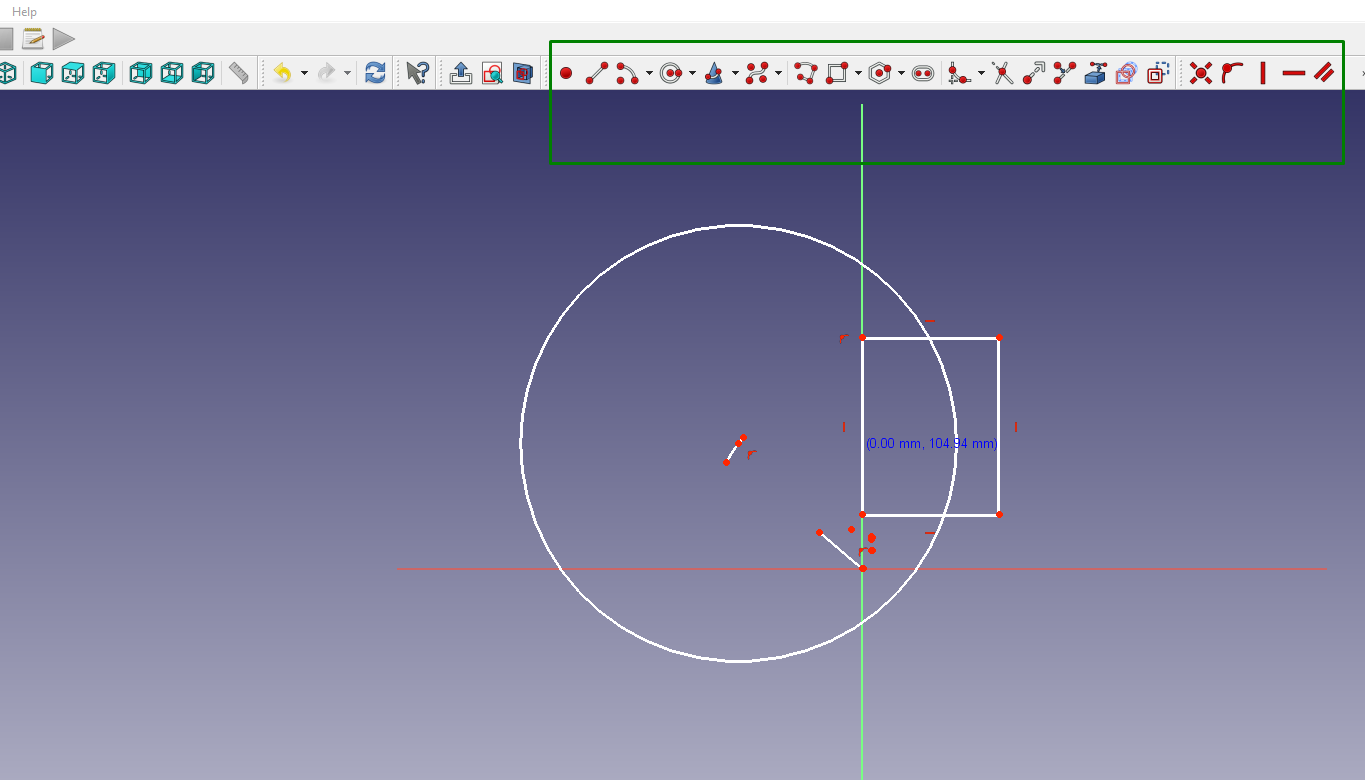
You can also choose Boolean operation if you would like to create the body by working with two or more bodies. If you select Sketch, you will see various sketching options available on the menu bar, and you can use them to create your drawings.
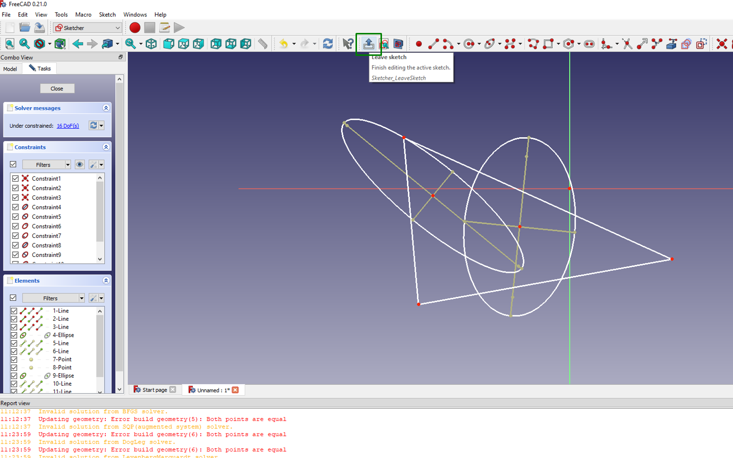
3. After sketching, click the icon to leave the sketch to finalize it.
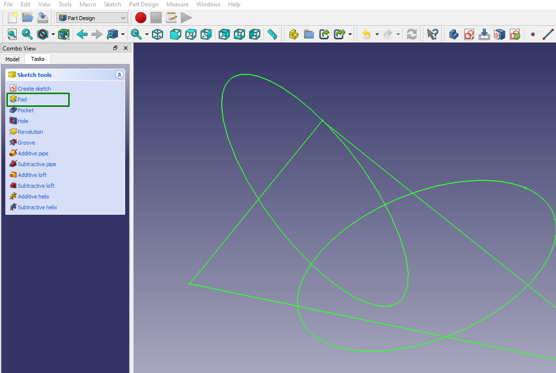
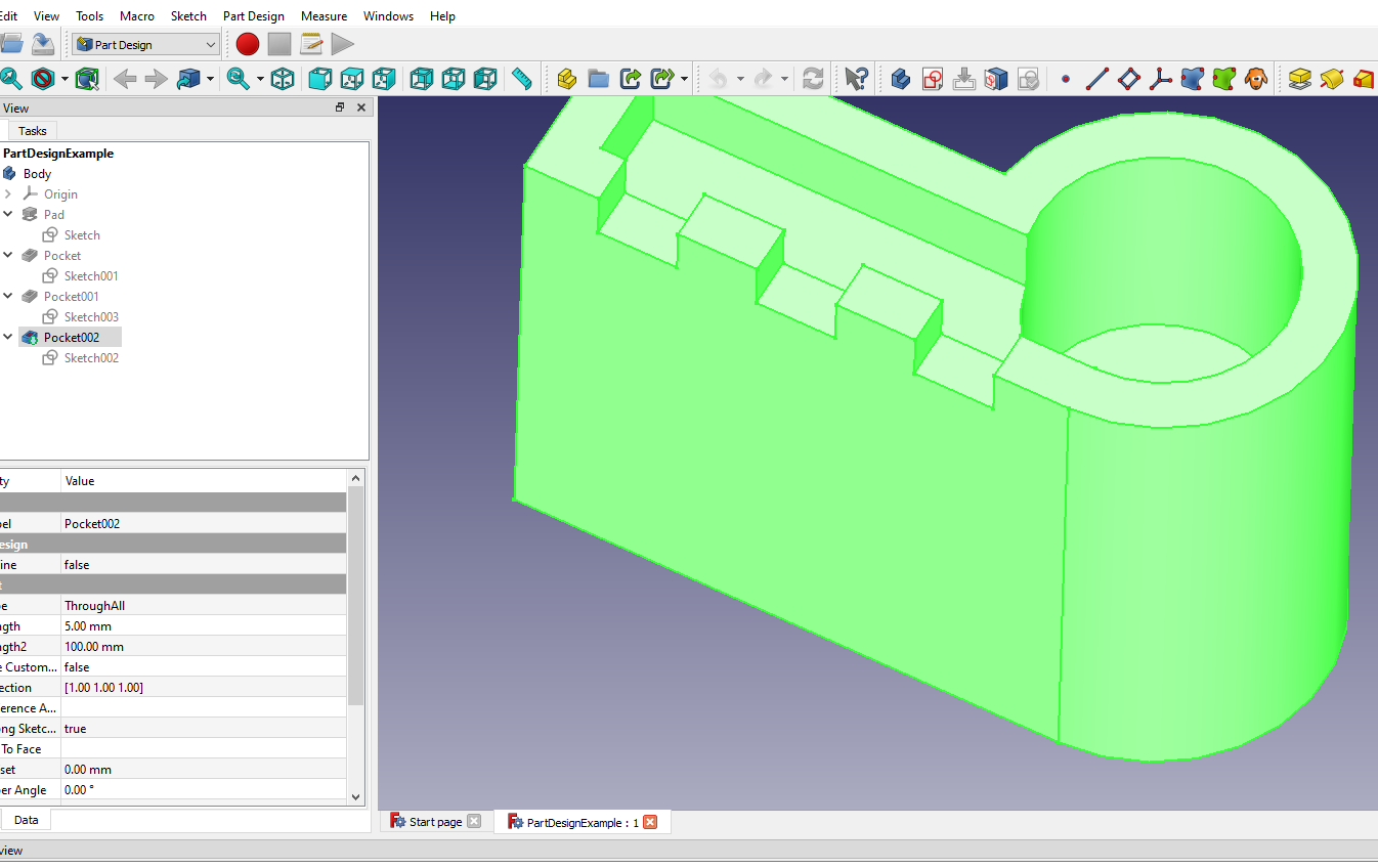
4. Choose the Pad tool from the left section of the workspace to extrude the sketch and turn it into a 3D model.
The extrusion process creates solid volumes from the flat sketches.
The Part Design workbench promotes a feature-based design approach. Each extrusion or modification you apply is a feature you can access and edit anytime. This allows you to adjust your model while maintaining a history of changes. In addition to extrusions, you can apply modifications like fillets (rounded edges), chamfers (beveled edges), and pockets (cutting away material) to refine the shape and appearance of your model.
In addition to the Part Design approach, you can use the Sketcher workbench to create 2D sketches that you can use as a foundation for 3D objects. In this method, you also use sketching tools to draw 2D shapes, lines, arcs, and other geometric elements. After that, you apply constraints to ensure the sketch is fully defined and maintains its intended shape.
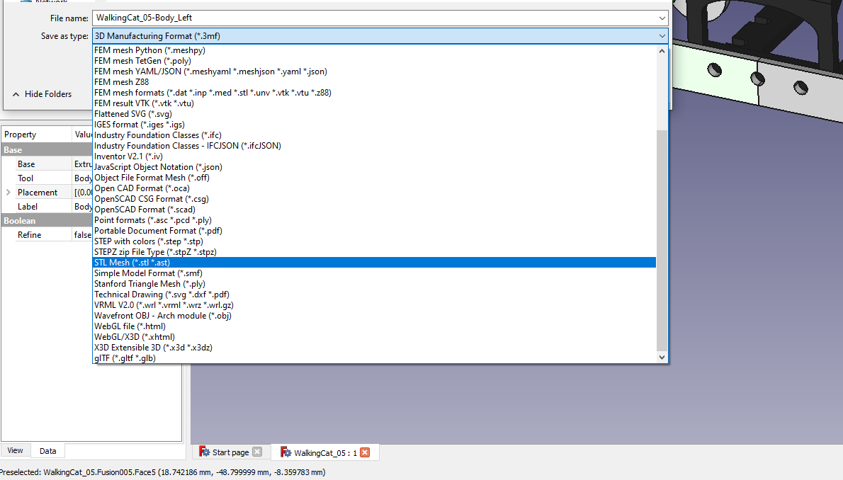
Once you finish creating your design, you can export it in STL format by going to File > Export and choosing the STL or OBJ file format.
This is the standard format used for 3D printing.
MORE: Best Budget 3D Printers
Converting Objects to Meshes in FreeCAD
After creating a solid object, we need to convert it into a format that 3D slicers can open: a mesh. However, note that once you convert a parametric object to a mesh, you lose all the parametric editing capabilities for that object. You can follow the steps below to convert an object to a mesh in FreeCAD.
1. Import your object by going to File > Import. Navigate to the location of the object file you want to import, select it, and click Open. You can proceed to the next step if you already have the design in FreeCAD.
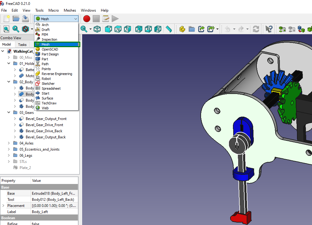
2. Switch to Mesh Design by selecting Mesh from the dropdown menu.
3. Select the object or part in the Model tree to convert to a mesh.
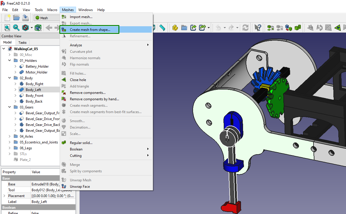
4. Go to Meshes > Create mesh from the shape with your object selected. This will open a dialog where you can set various meshing options.
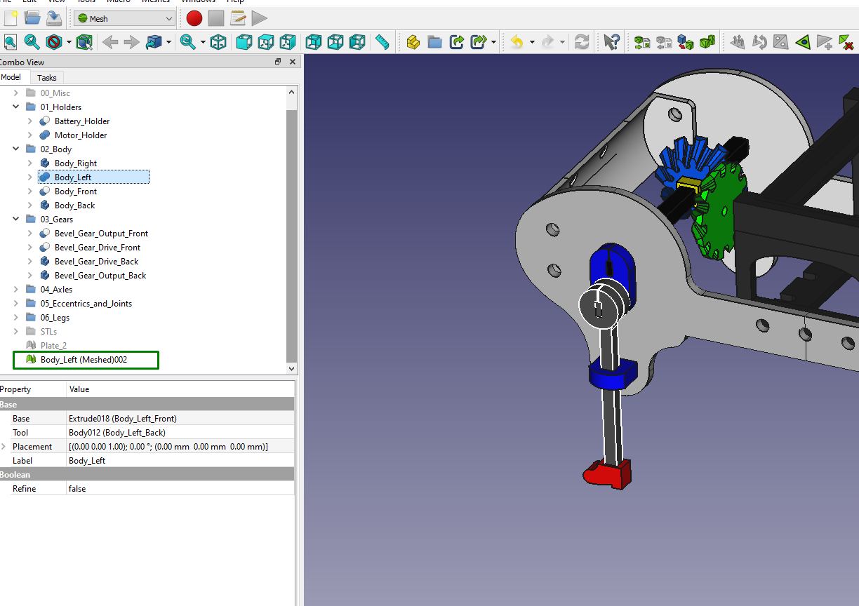
5. In the dialog, choose a meshing option and set the value of surface deviation. In my case, I retained the values in their default states. When you finish, click OK. A new mesh object should appear in the Model tree. You can see in the design below a new mesh is created.
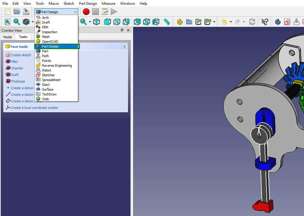
6. Another way to convert your object to a mesh is to choose Part Design on the menu bar.
Then go to Part > Create shape element > Convert to mesh.
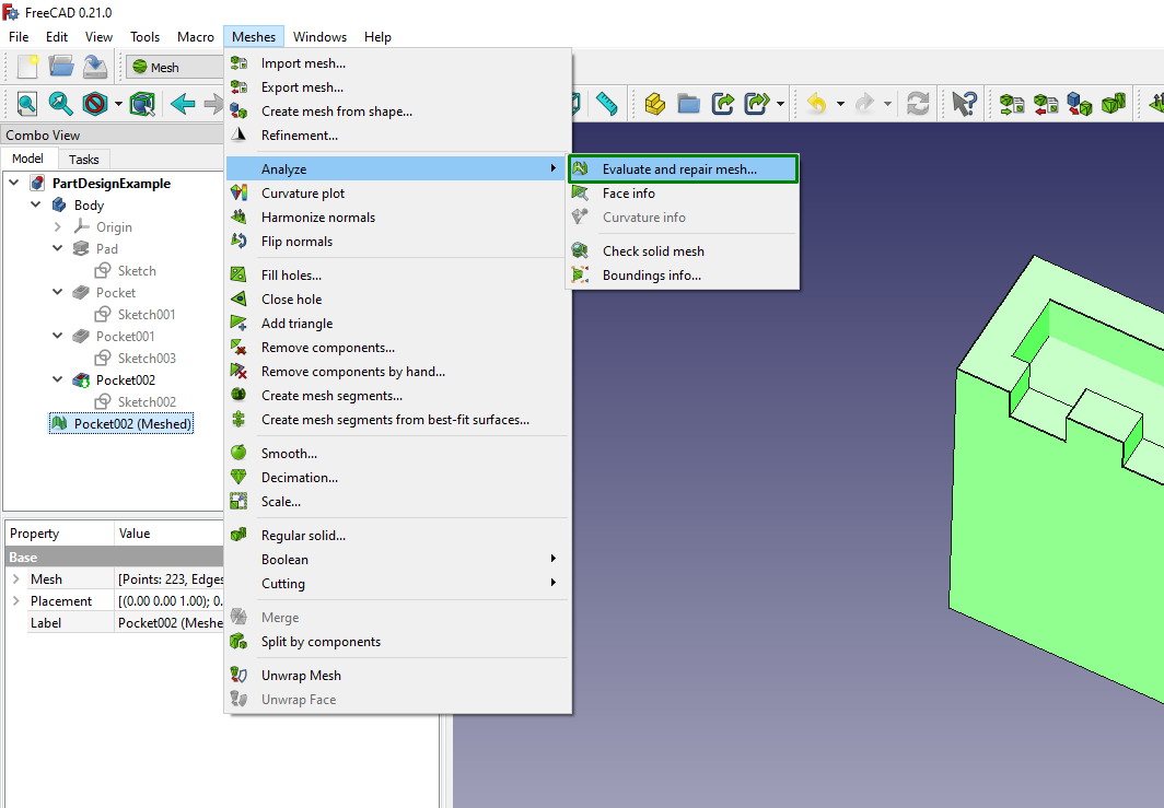
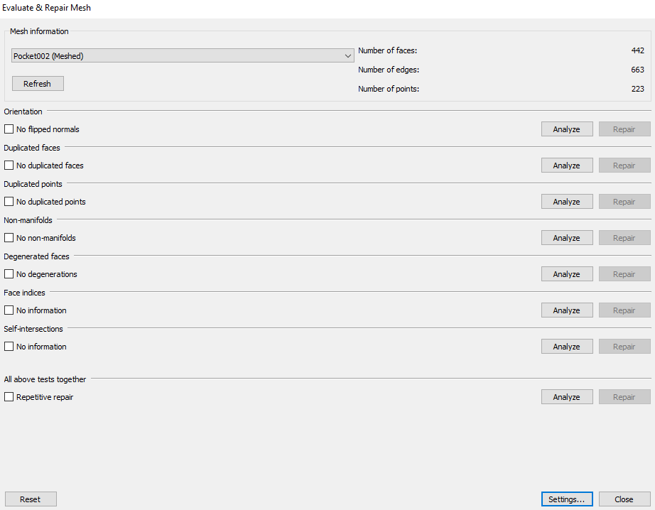
4. To save the mesh, select it, and then go to File > Export, and choose OBJ or STL. But before exporting, it’s crucial to analyze it first and see if there are any errors and fix them. To do this, go to Mesh > Analyze > Evaluate and repair meshes.
A new window will launch where you can analyze and repair if there is any issue.
You can also go to Mesh > Analyze > check solid mesh to confirm if your design is a mesh.
There are other mesh tools that you can use, and you can find them in the Mesh section on the menu. Some of the mesh editing tools include:
- Create mesh from shape: This allows you to create meshes from shapes.
- Refinement: This command will enable you to refine or coarsen the mesh, improving its quality and adapting it to your needs.
- Evaluate and repair mesh: Found in the analysis section; this allows you to evaluate and repair your meshes.
- Face info: You get to know the information of the faces in your mesh.
- File holes and close holes: For filling holes in your mesh.
- Remove components and remove components by hand: Remove faces and components from mesh objects.
- Cutting: In this section, you get options like Cust mesh for cutting faces from mesh objects, trim mesh for trimming parts, and faces from mesh objects. Create section from mesh and plane for creating a cross-section on the mesh object and Cross sections for creating multiple cross-sections on your mesh object.
- Merge: For combining meshes of two or more objects.
- Split by components: You can use this to split your mesh object into various components.
- Unwrap mesh and unwrap face: For creating flat representation of faces and meshes in your object.
MORE: Best Resin 3D Printers
3D Slicing From Cura in FreeCAD
You can use Cura slicer inside FreeCAD. Instead of designing your model in FreeCAD, saving it, and importing it to Cura to slice, you can install and use the Cura addon to FreeCAD. It is available in the FreeCAD add-ons repository. Once you download it, you can follow the steps below to install and use it. To install the add-on, I am going to show you two ways. One way is using the add-on manager of FreeCAD, and the second is using a terminal.
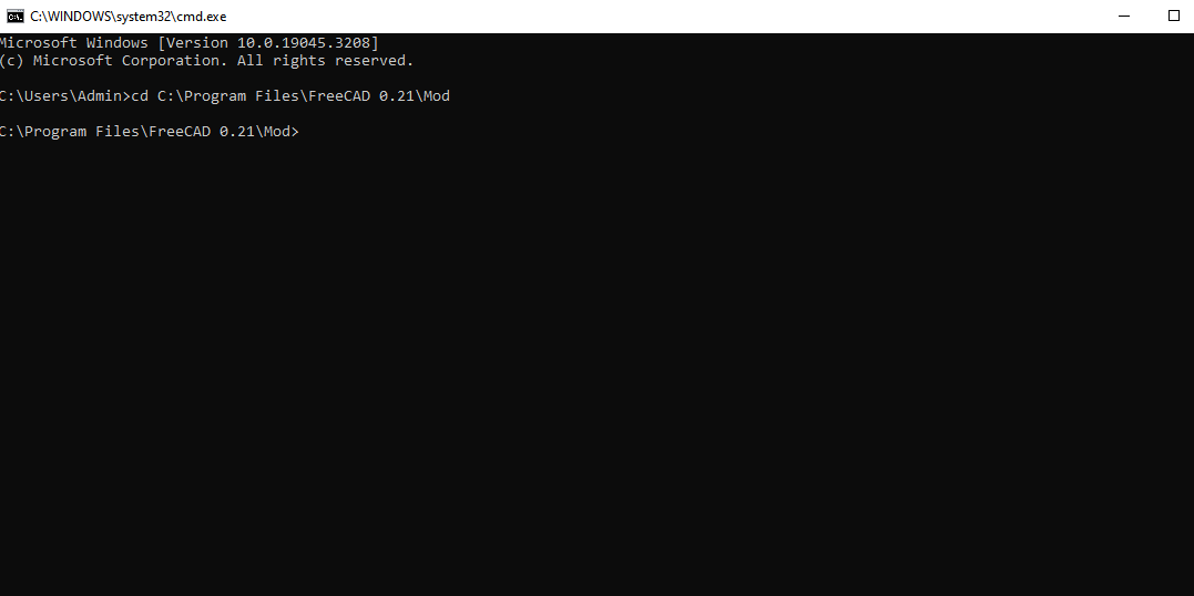
1. Open your command prompt and run it as an administrator.
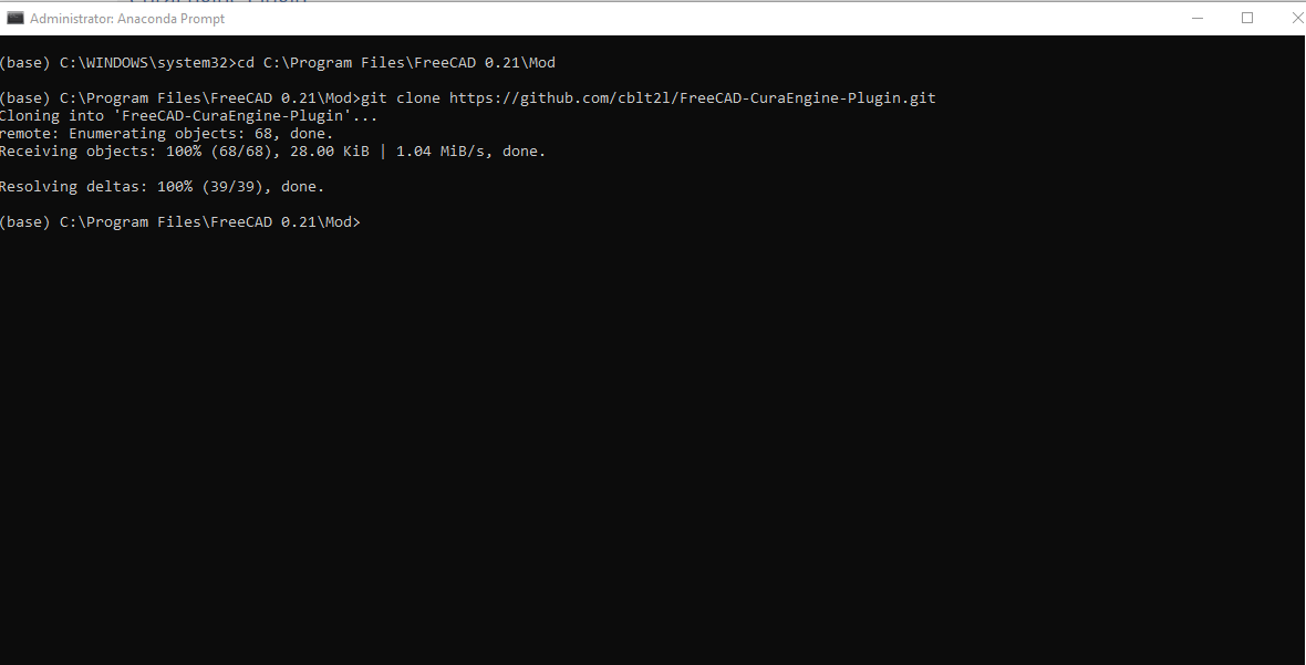
2. Navigate to FreeCAD add-on directory. If you are using Windows, it’s usually in C:\Program Files\FreeCAD 0.21\Mod. In your terminal, type CD followed by that directory.
3. Clone the repository directly using the command git clone [Addon Repository URL]. The URL is https://github.com/cblt2l/FreeCAD-CuraEngine-Plugin. Wait a few seconds, and you will see it’s installed.
4. Restart FreeCAD to activate the addon, and then go to View > Workbenches, and you will see 3D printing.
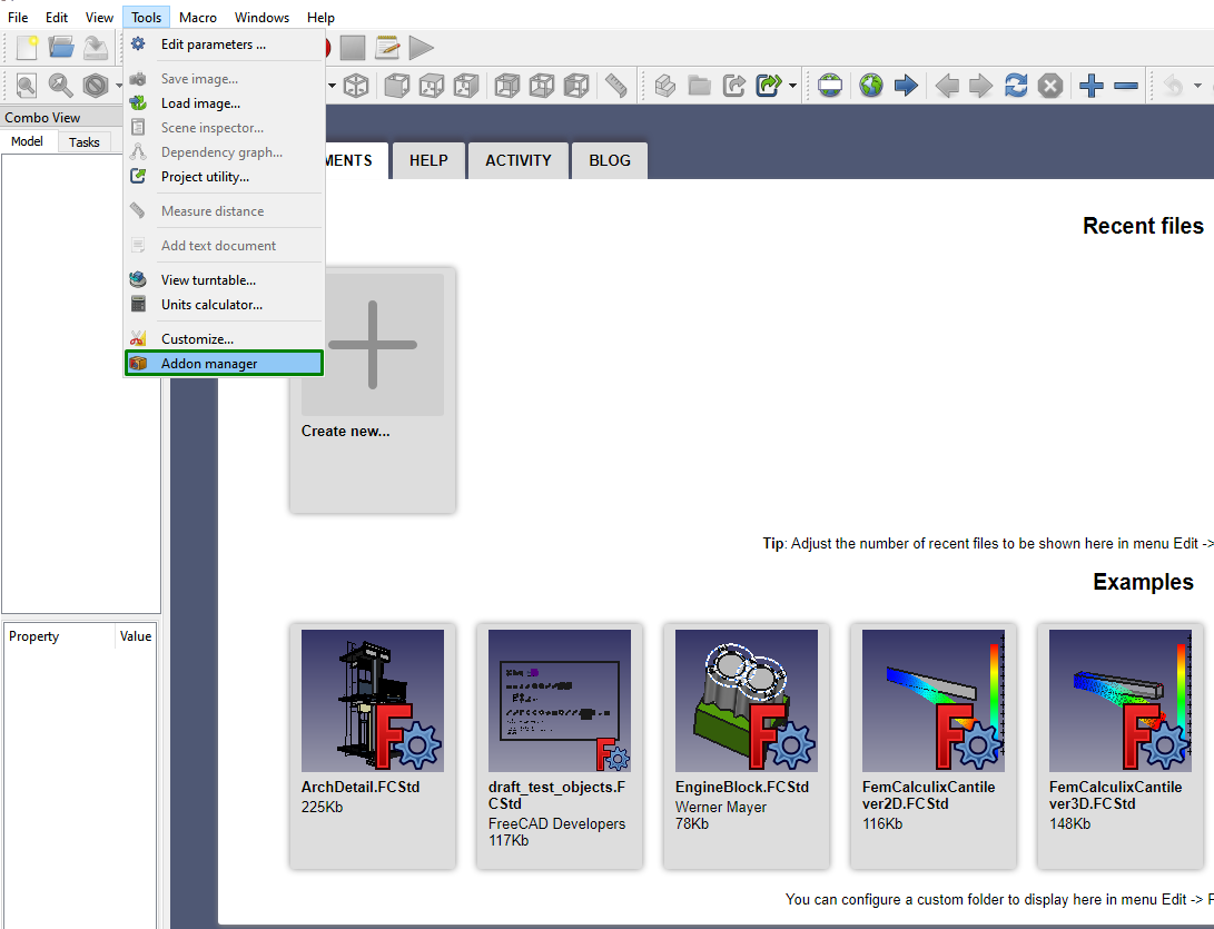
Another option to access a slicer in FreeCAD is to go to the Addon Manager section. To do this, follow the steps below.
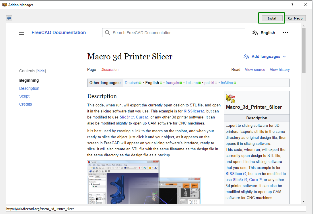
1. Go to Tools > Addon Manager.
2. Then select 3D printer slicer and click install.
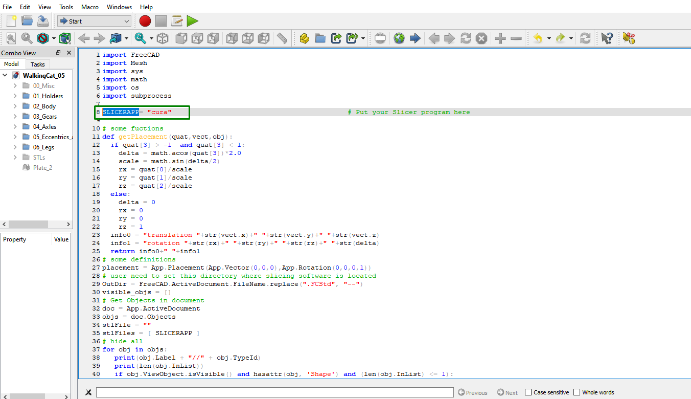
3. Run the macro, and you will see a code opening in the workspace. This is a Python script you can use to automate the slicing process of your files. Instead of downloading and exporting it to your slicer, it prompts the slicer to open and exports your design directly. You can change the slicer in SLICERAPP section. Mine is Cura, as that is the one I am using.
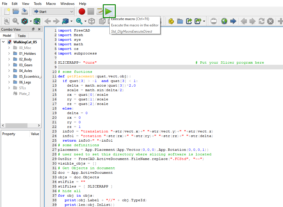
4. Click on execute the macro when you finish specifying your settings, and Cura will open, and you will see your file there.
This process is still tiresome, and you might face issues like the macro not executing you can simply export your design as an STL file and then import it to your 3D printer slicer.
Creating a G-code Using FreeCAD
Though FreeCAD is not primarily used for generating G-code, you can use it to do so, though the process is tiresome, unlike when you could download and import it to your preferred 3D printer slicer before sending it to your 3D printer. A G-code is the language that any of the best 3D printers understand. It controls the printers’ movements, speed, feed rate, and other settings. To create the G-code:
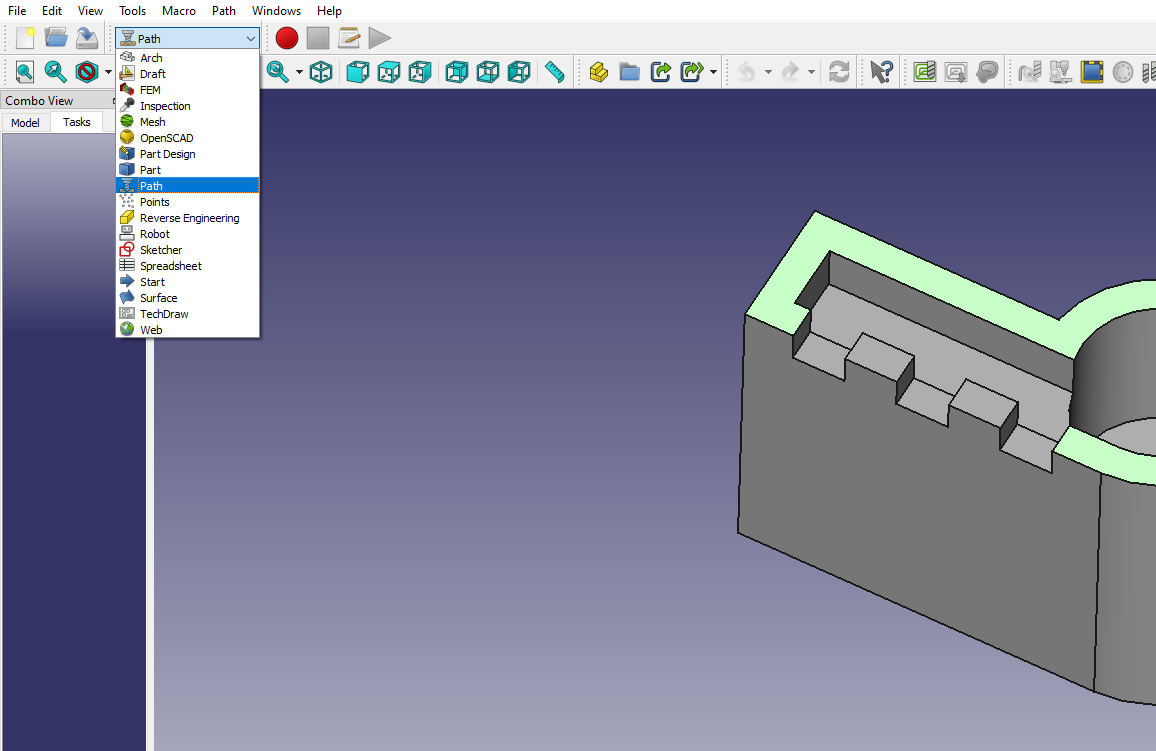
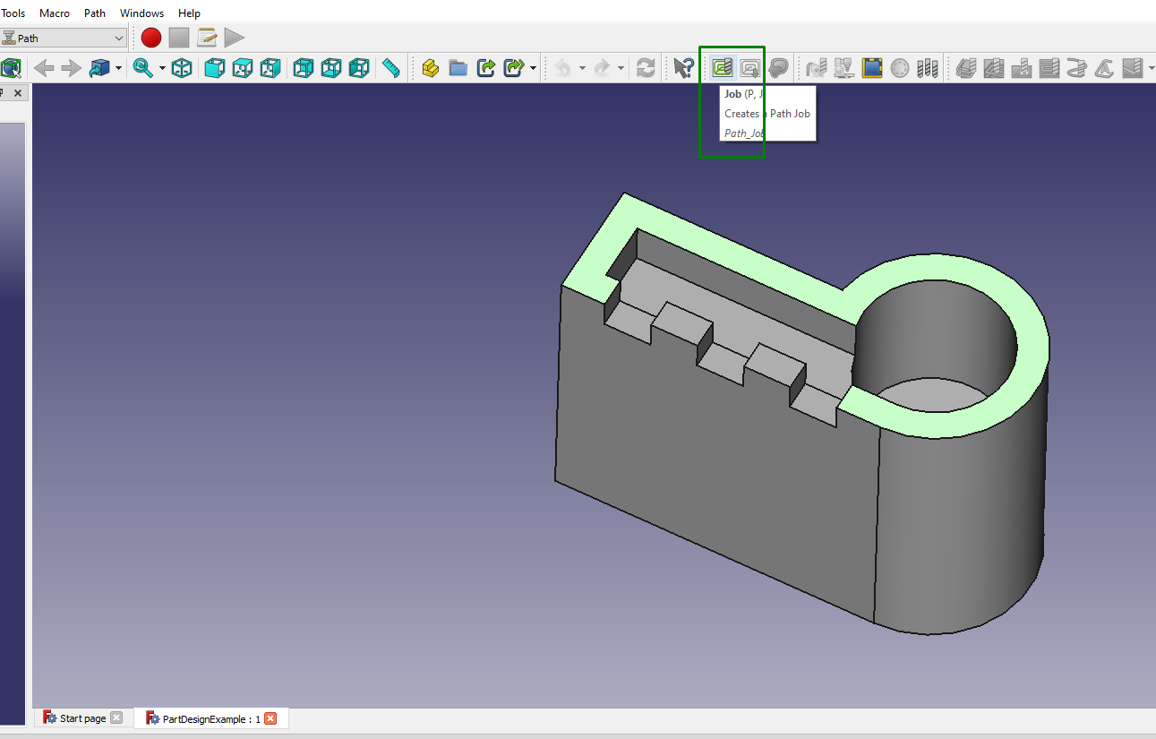
1. Switch to Path Workbench from the dropdown menu, as shown below.
2. Click on Job on the menu bar.
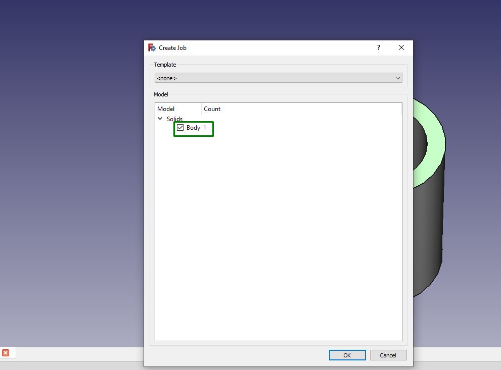
3. Click the checkmark for the body in the new window that launches.
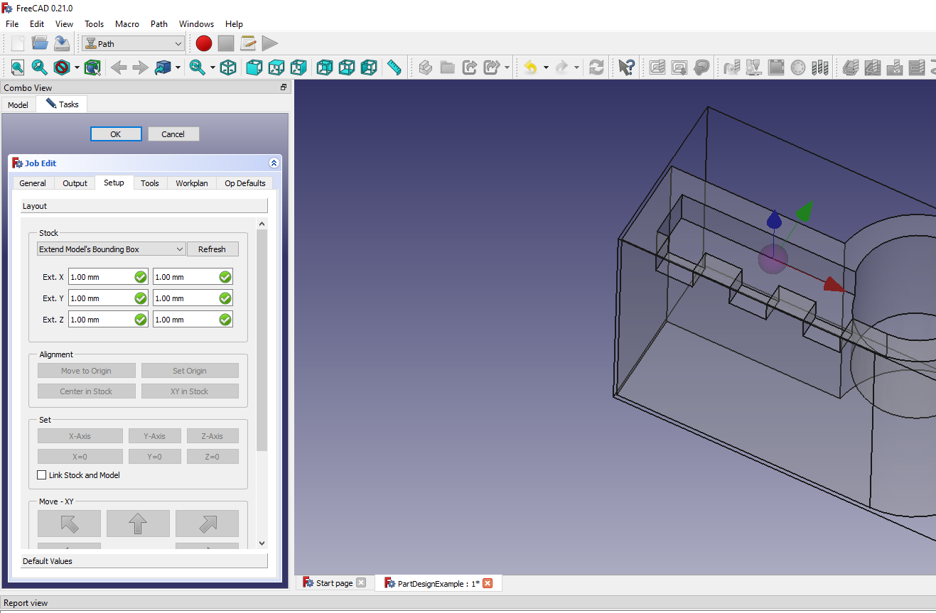
You will see the X, Y, and Z axis values on the left side of the workspace, and your design will change from solid to path, as shown below.
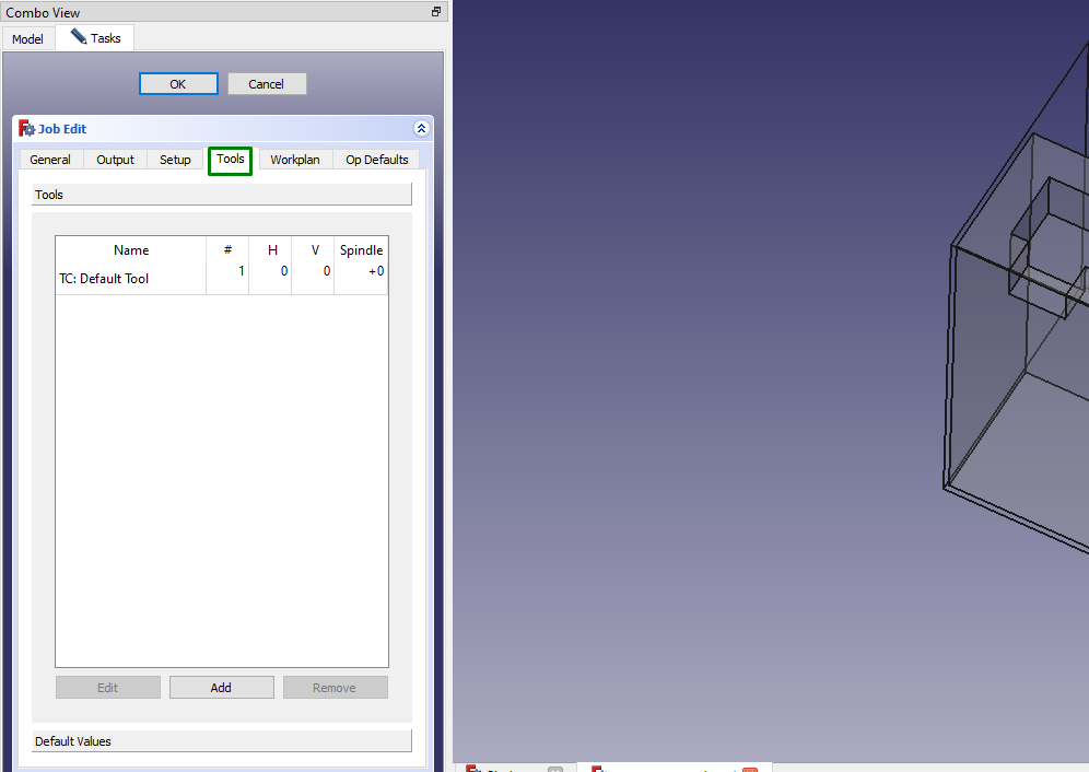
4. Next, you must define the tools you’ll use. Go to the Tools section in the window.
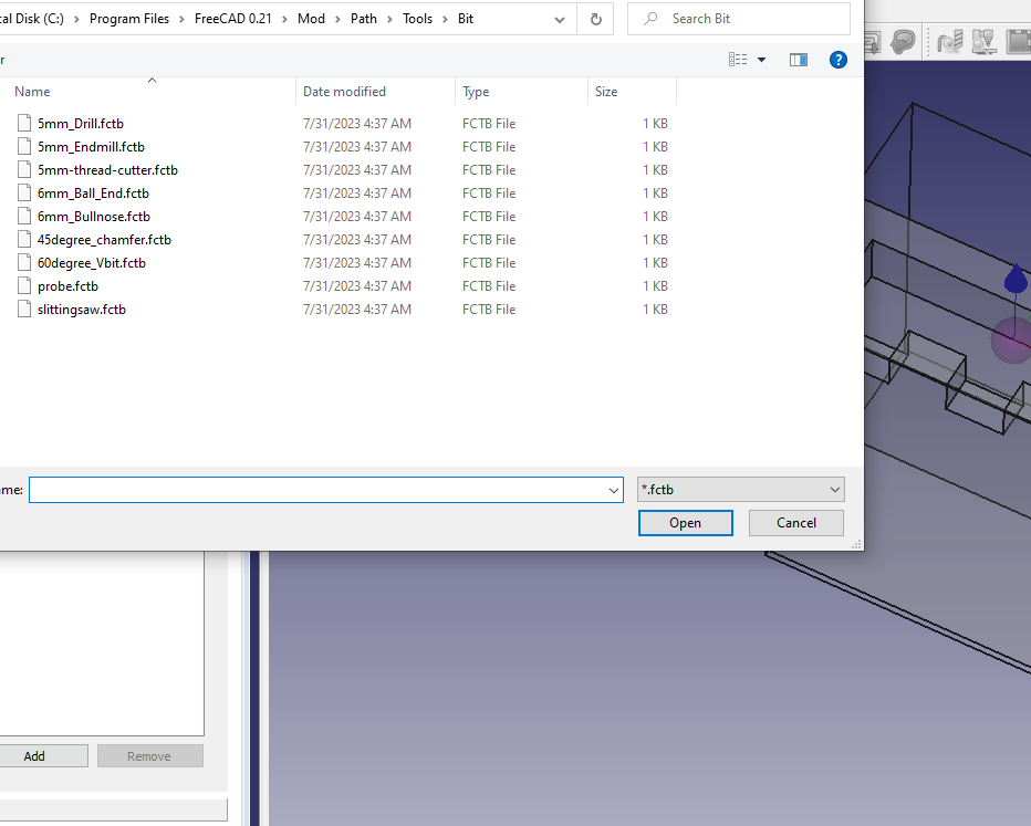
You can retain it as we are not using a CNC machine. If you are using CNC, you will click on the Add option, which will take you to the tools section, where you can select the most appropriate one.
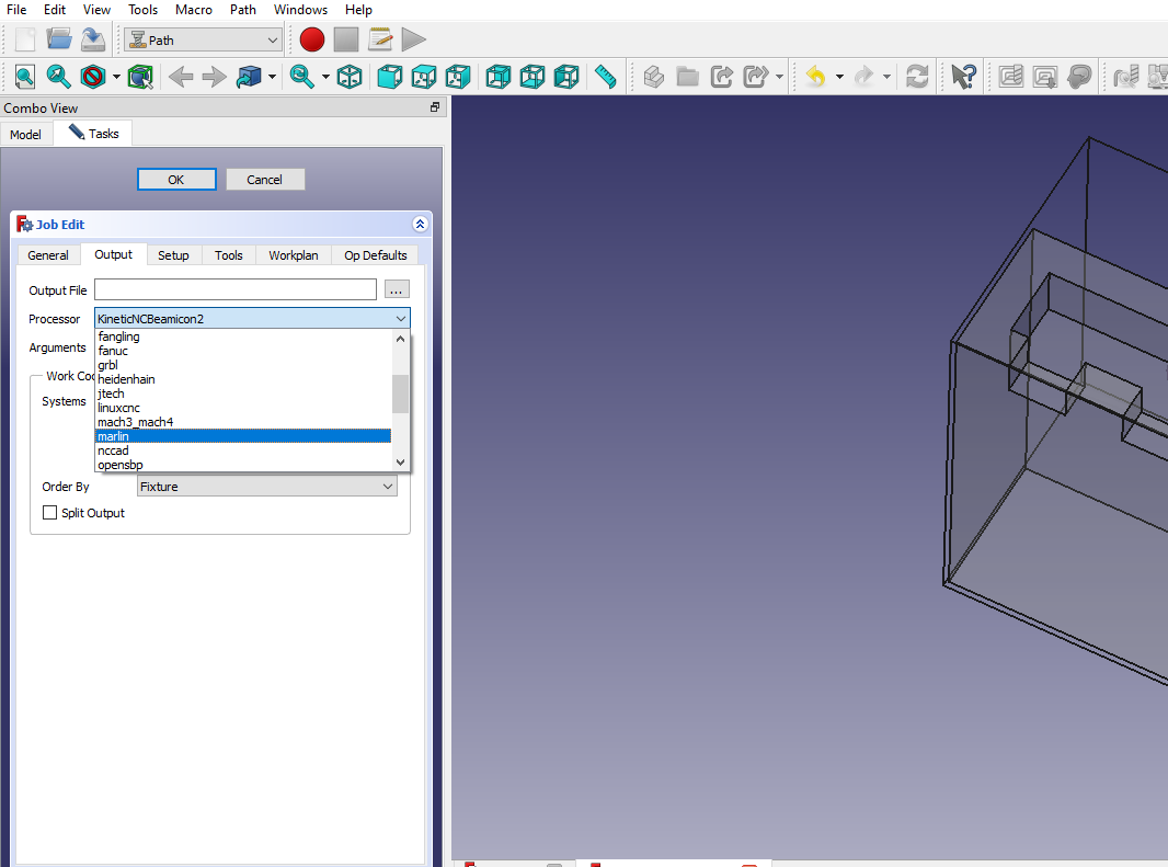
5. Next, we need to choose the processor that will be used. In the dropdown menu of the Output section, select Marlin.
Marlin is a firmware for controlling stepper motors and executing G-code, and it is primarily used in 3D printers, but you can also use it for CNC machines.
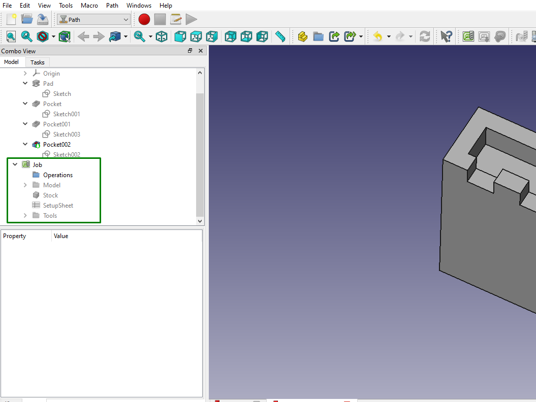
6. Click ok, and you will see a new job appearing.
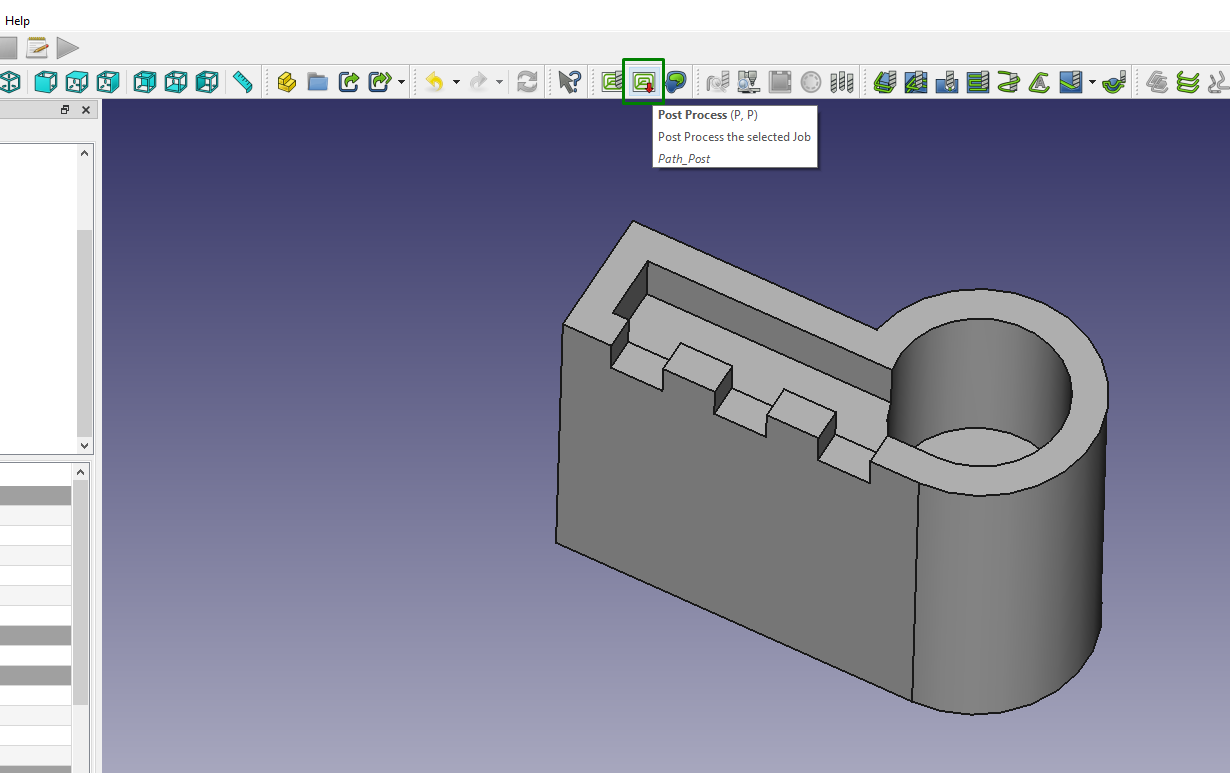
7. Select the job, then click the post process option in the menu bar to generate the G-code.
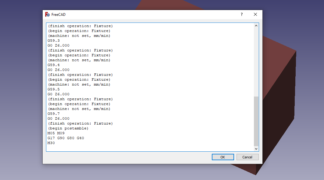
A new window will launch, and you will see your G-code generated. The one below is a sample G-code for a CNC machine and not for a 3D printer, as I selected the CNC machine in this tutorial for demonstration.
You can review the generated G-code to ensure it contains valid commands for your specific machine. With the above information, you should now be able to utilize FreeCAD for creating and preparing your designs for 3D printing.
More 3D Printing Tutorials
Sammy Ekaran is a freelancer writer for Tom's Hardware. He specializes in writing about 3D printing tutorials and guides. You can find more of his work on various publications, including Makeuseof, All3dp, and 3Dsourced.
-
Grobe If completely new to 3D software, the models shown in the article are too complicated to make without the basic skills. Luckily there are good video tutorials on youtube.Reply
I'm currently in the very start trying to learn to use FreeCAD myself this days. Nb: be aware that many of the tutorials are dated more than 2 years ago, and the GUI has changed since then (e.g. when importing images or svg files). One channel I follow to learn is the "mangojelly solutions" that have a ton of good videos out there.
As an extra bonus, the official forum for FreeCAD has being a good source for help, since even by following tutorials blindly, there are situations you can get stuck into.
