Antec Aria AR300 PSU Repair
Have you ever bought a computer case with a proprietary PSU form factor? What do you do when it eventually wears out? One option is to repair it.
The TL431 And You
What is a TL431? It is one of many widespread three-terminal programmable references, often referred to as programmable zener diodes due to how they mimic the zener diode's shunt mode voltage regulation.
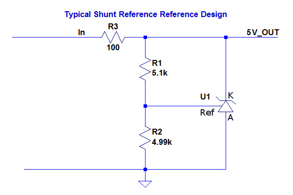
What is a shunt regulator? It is a regulator that works by sinking however much current as it has to or can across its main terminals to prevent the voltage across them from exceeding a set value, similarly to how surge protectors short out surge energy. In the programmable reference's case, the current it shunts from its cathode to its anode is a function of the voltage difference between the voltage applied to its reference pin relative to its anode and the device's own internal reference, 2.5V in this case. Using a simple voltage divider between the anode and cathode to drive the reference pin makes it possible to program any shunt voltage from the internal reference value (VRef tied to the cathode) up to its maximum voltage rating, provided that total power dissipation also remains within limits. If you read my SL300 repair, you saw my little shunt regulator schematic, which I used to drag the surging 5VSB output down to about 5.2V using a PNP transistor to boost the shunt current.
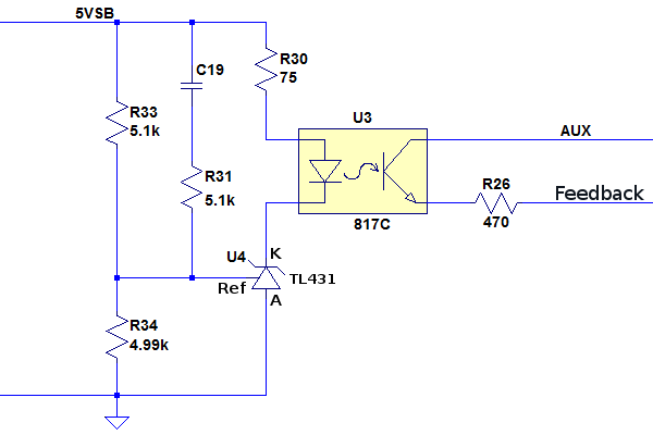
The TL431 and its countless variants from multiple power management and linear integrated circuit manufacturers are the duct tape of instrumentation electronics. They get used everywhere some sort of input needs to be weighed against a known quantity, and there are many creative ways to use them. In the case of power supplies, they function as comparators to drive the feedback photocouplers due to their flexibility and simplicity: two resistors to set the reference pin ratio, which sets the comparator's threshold, one resistor to limit current through the photocoupler, the *431 and the photocoupler, five parts in total, seven if you include an RC filter to improve transient response. Of course, it has other common uses as well, such as fan speed control and combining (ORing) feedback output from the 3.3V remote sense wire, as was the case in both the SL300 and AR300.
This is the AR300's actual 5VSB feedback circuit. If the 5VSB voltage is below roughly 5.1V, the resistor divider brings the reference pin below 2.5V, the reference stops drawing current and its cathode's voltage rises to rail voltage minus the photocoupler's diode voltage drop. If the output is above 5.1V, the resistor network pulls the reference pin above 2.5V, the cathode current increases, turns on the photocoupler, signaling the primary side to reduce power.
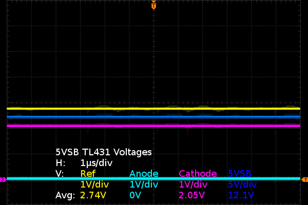
Looking at voltages around the AR300's 431, we see the reference pin at 2.74V and anode at 0V, which means it should be fully turned on. This is further confirmed by the 2.05V cathode-anode (VKA) voltage. The path from cathode to anode within the 431 and direct equivalents has three base-emitter junction voltage drops, and at about 0.65V each, 2V is just about the lowest possible shunt voltage. There is little doubt that the photocoupler and its current-limiting resistor are seeing the balance of the 12V currently present on the 5VSB output.
From the looks of it, the 431 appears to be working perfectly fine. Its state is consistent with a shunt reference trying to pull its cathode down as hard as it can. Time to move on to the next step: the photocoupler's LED.
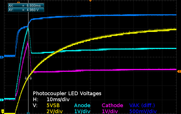
What does the signal across the photocouper's LED look like in action? I'm glad you asked since I have a screen capture of that--it is that 10VSB picture I said I would get back to later. Now is later.
Get Tom's Hardware's best news and in-depth reviews, straight to your inbox.
Here is what happens to the 5VSB feedback photocoupler LEDs as the 5VSB output starts ramping up after the power supply gets plugged in. Until the 5VSB output reaches 5V, voltage across the LED settles at about 1V due to the TL431's minimum operating current of about 100µA. Shortly after the 5VSB supply passes the 5V mark at the vertical cursor, though, voltage across the IR LED increases to 1.5V, indicating a significant current increase through it. You can also see the LED's anode and cathode voltages dropping by roughly 2V when the TL431 turns on. With 5VSB at 12V, the LED's anode at 3.6V and the 75Ω in-between, Ohm's law dictates about 112mA must be flowing through them, which is just over double what the 817 photocoupler's LED is rated for and slightly more than the 100mA the TL431 is specified at.
Despite the high current flowing through the LED, it appears to still be behaving like a typical infrared LED should, so I am inclined to believe it is still perfectly fine after possibly weeks of operating at more than twice its rated power. I did not take measurements while the power supply was connected to the motherboard so I have no idea exactly what the motherboard and 5VSB output were actually exposed to back then, and I had no intention of plugging it back in just to find out. I wonder how much longer this could have continued going on if I had not happened to need to use my Pentium 4 for a while longer. If the photocoupler's LED had failed, there would have been no feedback whatsoever left and things could have become much worse.
The fact that the 5VSB output was indeed 5V (if you overlook switching transients before I added external capacitors or replaced the internal ones) indicates that the primary side of the feedback loop was still at least sort of working, much like the SL300's. After investigation, it looks like it is none the worse for wear.
There's nothing more to see in the relative safety of the secondary side. It's time to start poking around the primary side.
-
iam2thecrowe That was a good read. I have a lot of custom power supplies (not PC atx) that i would like to fix at work instead of replace, would be a lot cheaper (there's some high wattage power supplies that cost $5000 to replace). Need to convince the boss to buy a good oscilloscope.Reply -
Rookie_MIB I have several of those cases - they make nice little machines for office use but the PSUs tend to flake. I've had to replace several...Reply -
Daniel Sauvageau All the standby power supplies I remember looking at are of the good old flyback design and one particularity of the flyback topology is that it has the worst ripple current on the output capacitors of all converter topologies or in other words: it is the harshest on output capacitors. Until I saw the waveforms while poking around the SL300, one little yet important detail skipped my mind: the harsh current waveform behavior applies to ALL outputs.Reply
Any flyback supply with sub-par output capacitors on any of its outputs will inevitably fail in relatively short order.
After that 'oops' moment, I decided to pop the lid on my LG 204WT which I thought had dying CCFL tubes, popped three of its auxiliary supply capacitors off the board, measured them at 5-20 ohms of ESR, replaced them, no more flicker or random turn-on issues. -
gnyff I love it when stuff is repaired! It's so sad that almost every consumer device today is made to fail and be replaced. Even in the cases where the designer did not specifically design for failure most commonly it's definitely not cost-effective for the user to have it repaired. :-(Reply
Anyways, I've also replaced one of those lousy non-standard PSU. Hard to find and depressingly expensive. Thus, I am avoiding non-standard parts as much as possible now! ;-)
By the way, in one of my systems the standby power was around 12W (!) even after shutting off 5VSB functions (wake on LAN, keyboard etc) in the BIOS. I did on bother to investigate further (thinking "lousy supply"!) and simply added a proper "full off" power switch. Probably other owners should think of doing the same ;-) -
Rookie_MIB Reply16509494 said:Anyways, I've also replaced one of those lousy non-standard PSU. Hard to find and depressingly expensive. Thus, I am avoiding non-standard parts as much as possible now! ;-)
By the way, in one of my systems the standby power was around 12W (!) even after shutting off 5VSB functions (wake on LAN, keyboard etc) in the BIOS. I did on bother to investigate further (thinking "lousy supply"!) and simply added a proper "full off" power switch. Probably other owners should think of doing the same ;-)
I wonder if a SFX PSU could be mounted in those cases. Might be a viable solution... -
nukemaster Another great one!Reply
I actually was interested in that case back when it was released, but just kept rocking the Sonata and Sonata II. While my power supplies did not fail. caps leaked after a while(power supplies still worked)and I took the power supplies out of service forever.
Rookie_MIB,
SFX would be an interesting idea to see for sure. My SFX is still going after 5 years of 24/7 operation(not bad for a case included 300 watt unit). -
Daniel Sauvageau Reply
The dimensions might fit but mounting holes would be on the wrong side (for mounting in a way that might fit internally) and the IEC socket would face either the motherboard or the top cover. Nothing some drill-and-tapping with some wire splicing cannot fix for people who would favor this route instead of a repair of the existing unit where that is possible.16509868 said:I wonder if a SFX PSU could be mounted in those cases. Might be a viable solution...
BTW, the total repair cost for the 5VSB side is about $1.50 for the caps and resistor. The rest is basically free since I scavenged the SCs from a dead (catastrophic primary-side failure) PSU and would have cost around $2.50 otherwise. If Asus had specified higher quality parts from Channel Well though, the PSU may have cost less than $0.50 extra to get right on the first try. Evem doing as little as specifying Teapo SC as the minimum requirement would have easily doubled the trouble-free service life over using SEK..
It always bugs me when only a few pennies worth in parts and materials can spell the difference between a product that might only last 2-3 years and a product that should easily last 10+ years. -
nukemaster That small cost per unit adds up.Reply
I can not count the number of times I say, gee a xx cent part would have solved this damn issue and yet no one does it.
Drilling and making it fit is no issue. :)
I still get my small system fix with an SG05 case.
Where do you get your parts from? Digikey is not too expensive, but many times the shipping cost more than the parts(especially with resistors that are cheap to begin with.). -
Daniel Sauvageau Reply
The "small cost" may add up but if you charge $1 to put the $0.50 worth of better quality parts in, you still make a 100% profit on that extra cost and you score points in the quality/reliability column. For the most part, those better quality parts are the same physical size, so no fitting or PCB layout concerns there.16511613 said:That small cost per unit adds up.
Where do you get your parts from? Digikey is not too expensive, but many times the shipping cost more than the parts(especially with resistors that are cheap to begin with.).
As for where I get my parts, they are mostly Digikey. I either lump my order with parts I need to repair something for someone else (and pass the shipping cost to them) or build my order for multiple non-urgent projects until it qualifies for free shipping.
Edit: and for things like 0805 resistors and capacitors, I usually order in cut-tapes of 100 since we're still only talking $1-2 there. If I had more storage space, I would order whole reels for $10-15 (2000-3000 units) and likely never have to worry about ordering more of that resistor or capacitor value (for personal use) for the rest of my life. -
pjmelect I often repair computer power supplies and I enjoyed reading this article. One comment, that may help others and may explain some things in the article such as the power reduction of the fixed power supply.Reply
Capacitors with high ESR always have a very high leakage current near their rated voltage. The leakage current at low multi-meter voltage levels is not normally measurable, but increasing the voltage across the capacitor dramatically increases the leakage. Circuits with capacitors with high ESR in them normally fail not due to the ESR or the reduction of capacitance, but due to the high leakage current. If you do not have a ESR meter you can simply put a suspect capacitor across a power supply at its rated voltage and check the leakage current. A high leakage current is a good indication of a high ESR value.
I use a in-circuit ESR meter to test all of the electrolytic capacitors (even the small ones) before I even start trying to fault find a power supply.


