Super Flower Leadex Titanium 1600W Power Supply Review
Corsair's mighty AX1500i PSU must now face some stiff competition, as Super Flower's new Leadex Titanium 1600W offers even more power and efficiency.
Why you can trust Tom's Hardware
A Look Inside And Component Analysis
Our main tools for disassembling PSUs are a Thermaltronics soldering and rework station and a Hakko 808 desoldering gun.
Parts Description
| Primary Side | |
| Transient Filter | 6x Y caps, 2x X caps, 2x CM chokes, 1x MOV |
| Inrush Protection | NTC Thermistor & Electromagnetic Relay |
| Bridge Rectifier(s) | Bridgeless Design - 1xΒ US30K80RΒ & 8x Infineon MOSFETs |
| APFC MOSFETs | 8x Infineon MOSFETs |
| APFC Boost Diode | 4x Infineon IDL10G65C5 |
| Hold-up Cap(s) | 4x Nippon Chemi-Con (400V, 390uF each; 1560 uF combined, 105 °C, KMW) |
| Main Switchers | 4x IPP50R140CP |
| APFC Controller | SF29603 |
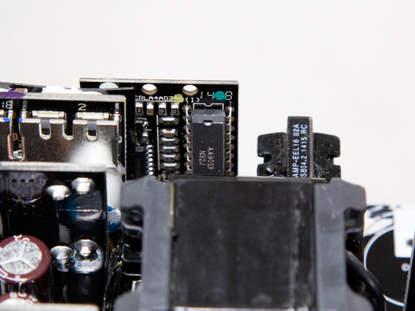
| Switching Controller | SFAA9013 |
| Topology | Primary side: Bridgeless PFC & Full-Bridge LLC & Resonant Converter Secondary side: Synchronous Rectification & DC-DC converters |
| Secondary Side | |
| +12V MOSFETs | 12x Infineon BSC027N04LS |
| 5V & 3.3V | DC-DC Converters: 8x Infineon IPD060N03Β FETs |
| Filtering Capacitors | Electrolytics: Chemi-Con, 105 °C, KY & KRG Polymers: Chemi-Con |
| Supervisor IC | AA9013 (probably) & LM324ADG |
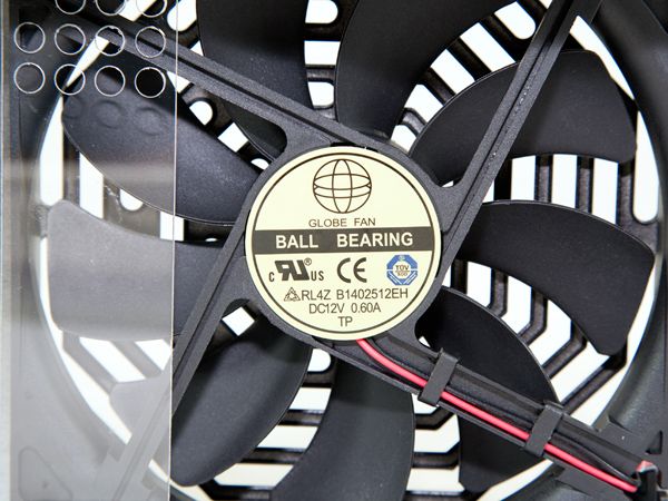
| Fan Model | Globe Fan RL4Z-B1402512EH (140mm, 12V, 0.6A, 2000 RPM, 153.47 CFM, 39.5 dB(A), 70,000-hour MTBF) |
| 5VSB Circuit | |
| Rectifying Diode | Mospec S10C60C |
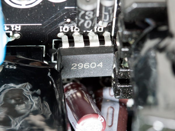
| Standby PWM Controller | 29604 |
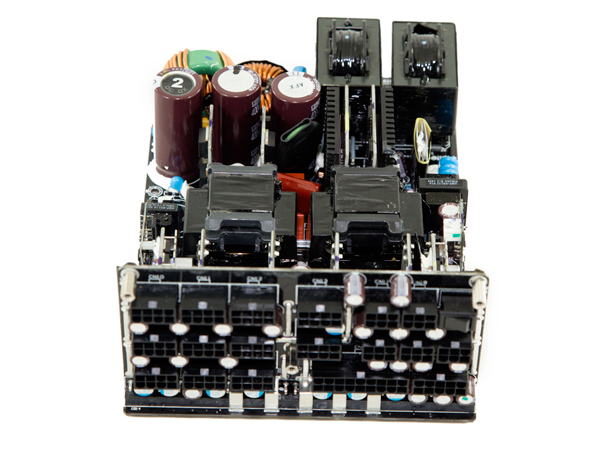
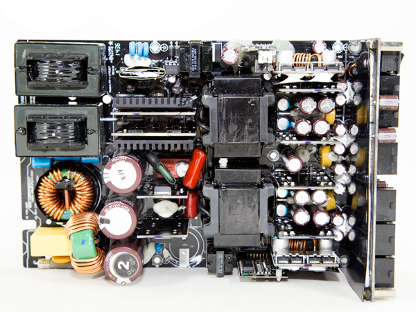
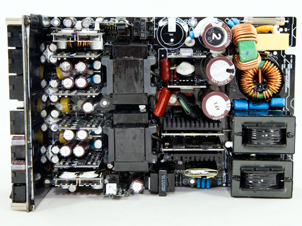
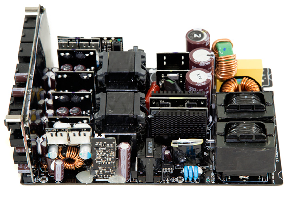
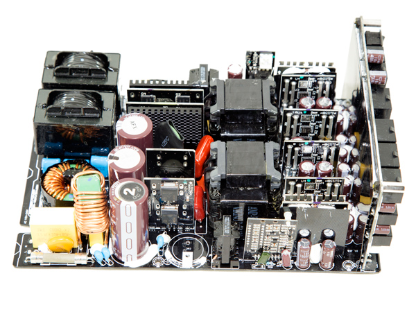
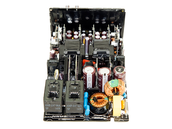
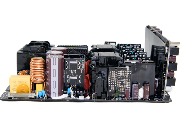
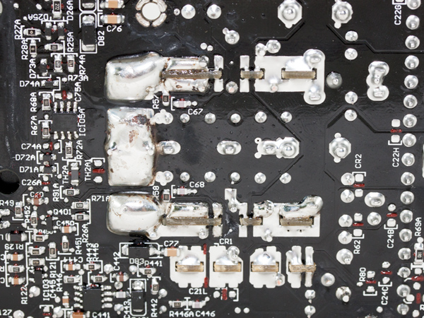
The PSU uses a modified version of the EVGA 1600 P2, which we previously reviewed. This is a modern design featuring a bridgeless APFC converter, along with a full bridge topology and an LLC resonant converter for improved efficiency. In the secondary side, only MOSFETs (metal-oxide-semiconductor field-effect transistors) are used for the regulation of the +12V rail, while two DC-DC converters or voltage-regulation modules (VRMs) handle the minor rails.
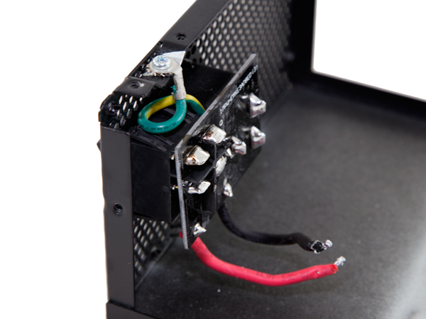
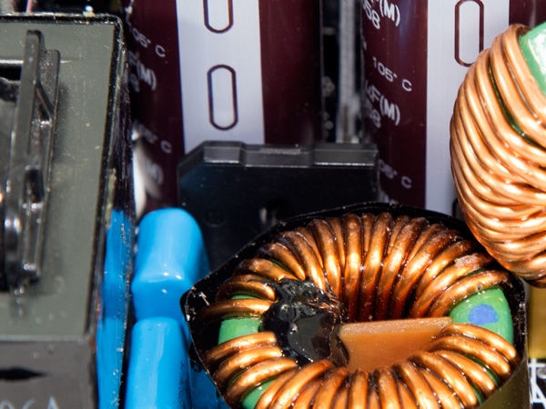
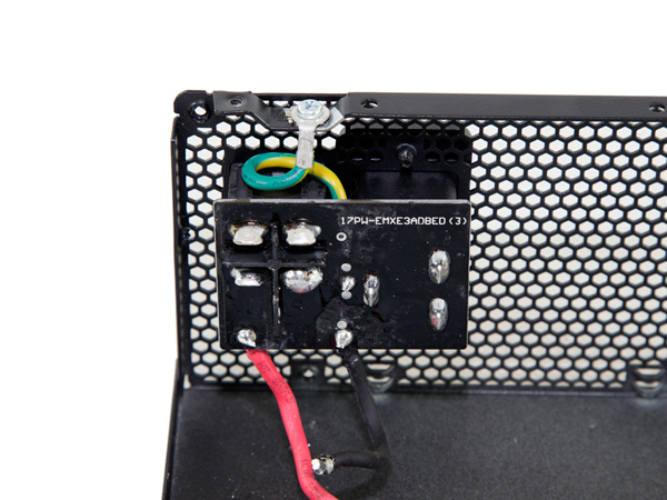
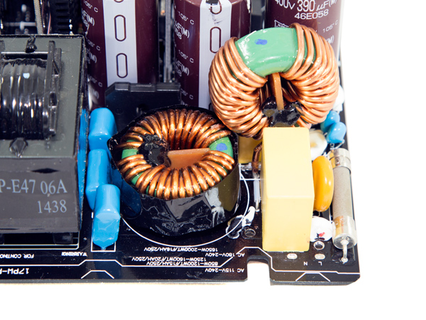
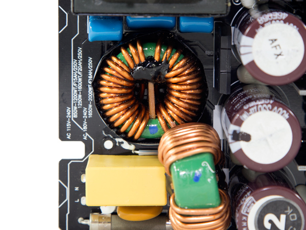
A small PCB hosts the AC receptacle and the on/off switch. All parts of the EMI/transient filter are installed on the main PCB, including three pairs of Y caps, a pair of X caps, an MOV and two CM chokes.
The single US30K80R bridge rectifier is probably only used by the 5VSB rail, since the main rectification takes place in the APFC converter.
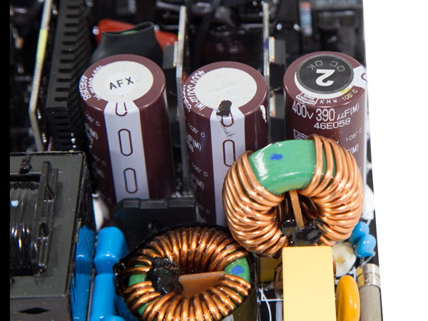
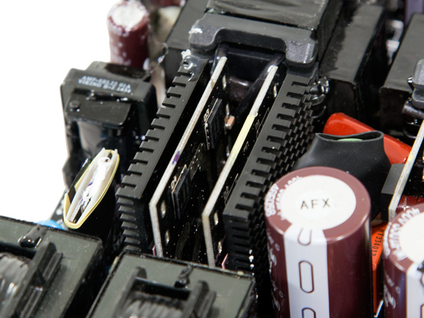
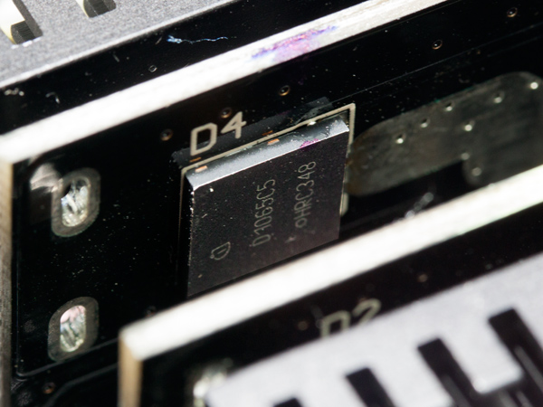
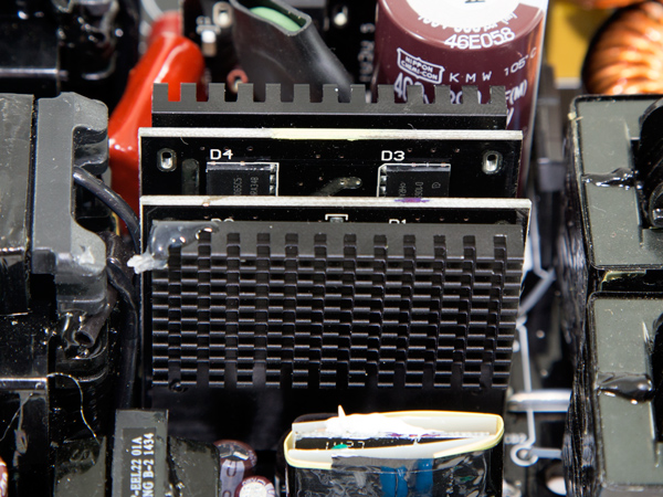
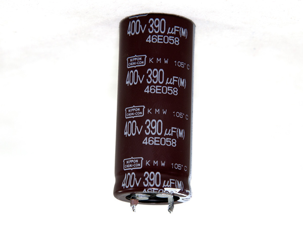
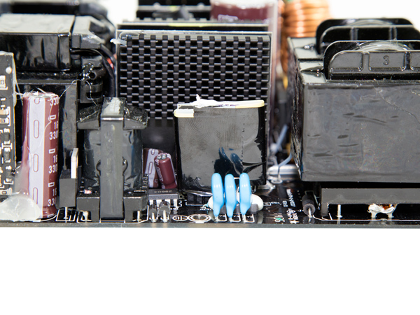
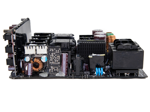
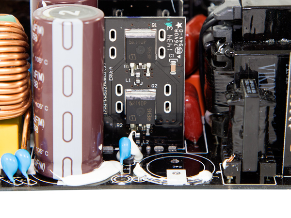
In the APFC converter, eight FETs fully rectify the AC mains voltage and, at the same time, shape the current waveform to match the voltage. This helps to bring the power factor closer to unity by restricting the flow of reactive or apparent power back to the source. In addition to the above FETs, we found four Infineon IDL10G65C5 boost diodes. The bulk caps are four parallel Nippon Chemi-Cons (400V, 390uF each, or 1560uF combined, 105 °C, KMW).
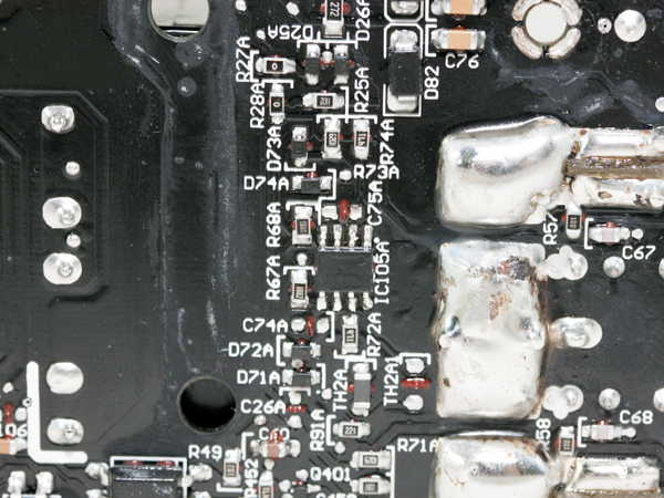
The PFC controller is an SF29603 IC, for which there is no documentation available. It is installed on the shielded PCB, located in the APFC converter's area.
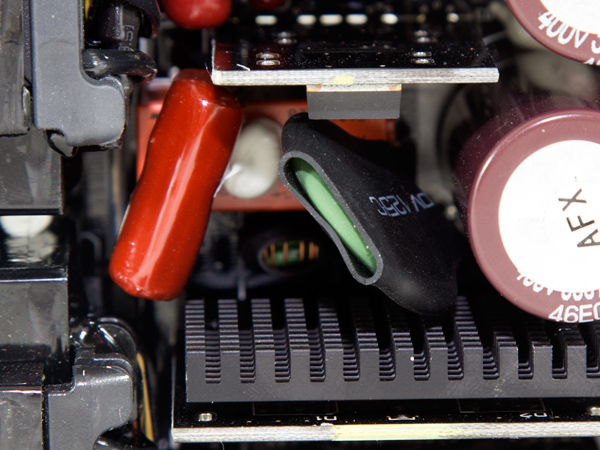
A pretty large negative temperature coefficient (NTC) thermistor provides protection against large inrush currents that occur during the PSU's start-up phase. An electromagnetic relay isolates the thermistor once the APFC capacitors are fully charged, allowing it to cool down while providing a small efficiency boost, as this NTC has some resistance even at high operating temperatures.
Get Tom's Hardware's best news and in-depth reviews, straight to your inbox.
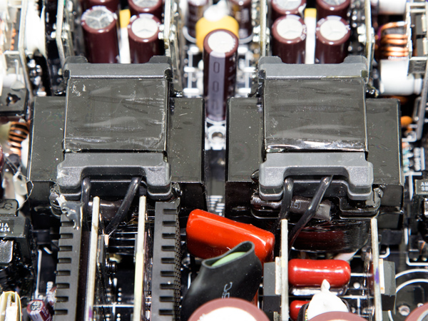
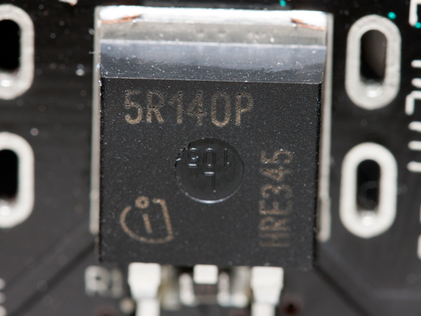
We removed one of the APFC's capacitors to provide you with a better view of the main switchers. The four Infineon IPP50R140CP main switchers are arranged into a full bridge topology, which is ideal for high power outputs. At the same time, it is able to provide good efficiency levels. An LLC resonant converter is also used for a significant efficiency boost.
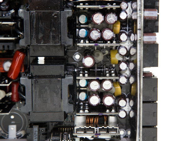
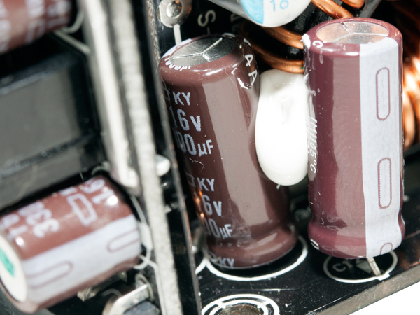
To restrict energy loss—and because there was no space for a single large main transformer—Super Flower uses two smaller parallel transformers. Between the main transformers and the modular PCB are many electrolytic capacitors rated at 105 °C (KY series), along with some polymer caps. All of them are provided by Nippon Chemi-Con, so the caps are of high quality.
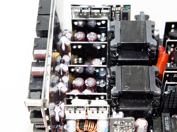
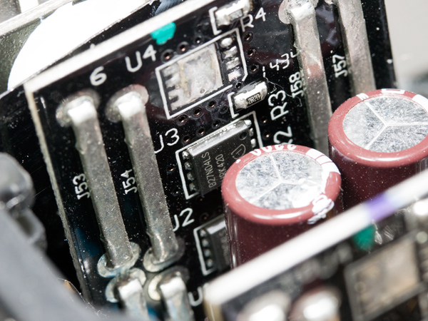
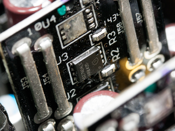
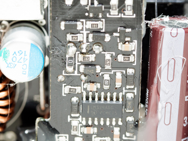
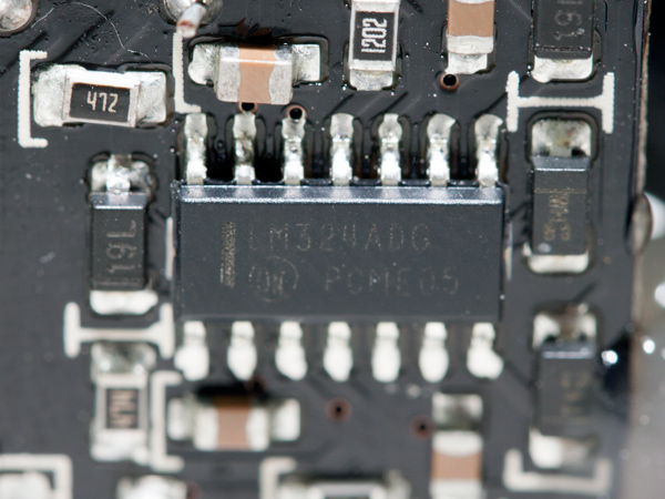
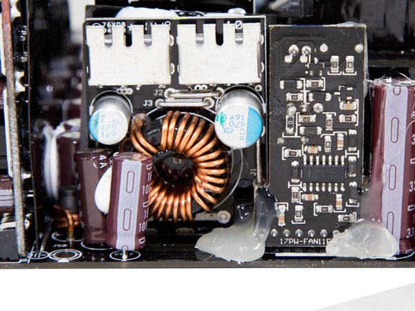
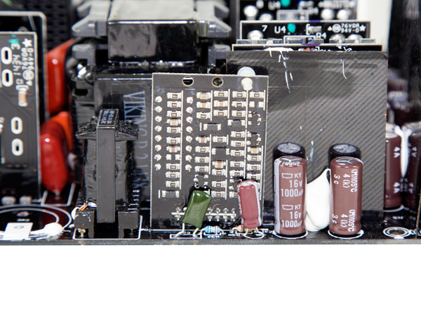
We found that all FETs rectify the +12V rail on four vertical daughterboards. Twelve Infineon BSC027N04LS MOSFETs are used for this purpose—fewer than the 16 BSC035N04LS that are used in the Platinum version of this platform. The first type of FETs (model number BSC027N04LS) have a smaller RDS (on) value, which leads to significantly lower power losses, especially as the load increases.
We applied lots of glue at the PCB that holds the fan header while trying to remove the fan from the PSU. Super Flower should look into this matter closely and either attach the fan header directly onto the main PCB or reinforce the base of the PCB. On the daughterboard that houses the fan control circuit, an LM324ADG operational amplifier (op-amp) is installed, and a little farther up there is a Mospec S10C60C SBR, which generates the 5VSB rail.
The standby PWM controller is an IC with the number 29604 written on it—a clue that didn't help us find any information about it.
The resonant controller is the AA9013 IC, which is used by all Leadex platforms. There is also an LM324ADG op-amp on the same PCB that hosts this controller.
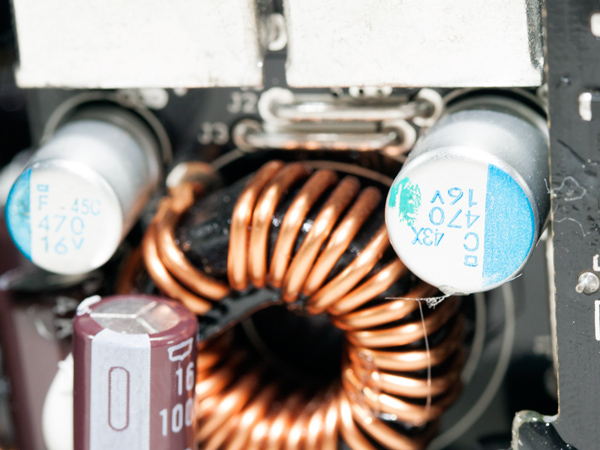
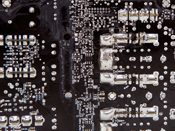
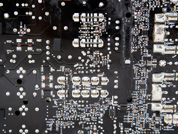
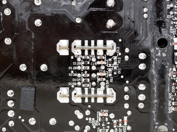
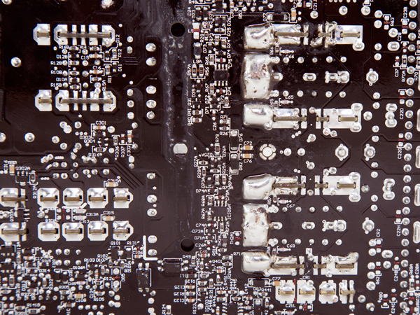
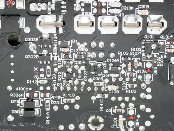
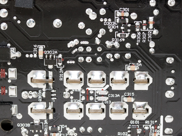
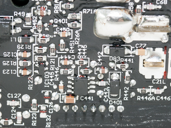
Two DC-DC converters generate the minor rails. Both of them use Chemi-Con polymer caps.
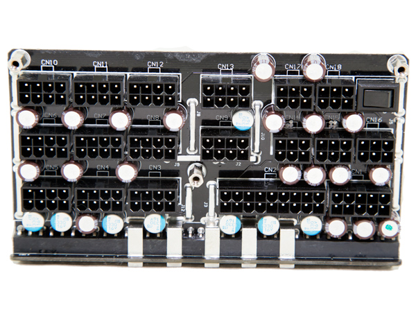
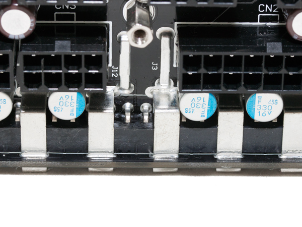
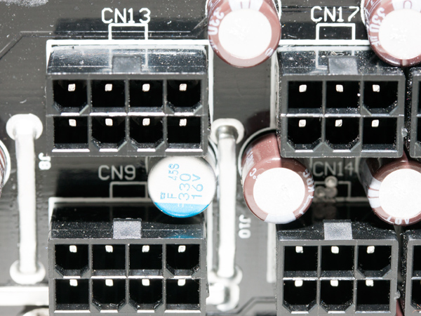
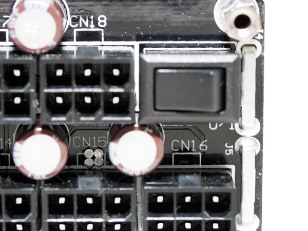
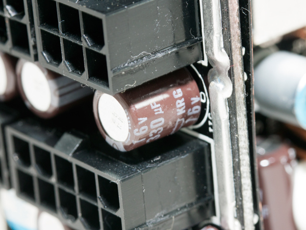
On the front of the modular PCB, we found lots of sockets as well as a multitude of polymer and electrolytic caps, which provide some extra ripple filtering; all of these caps are also manufactured by Chemi-Con.
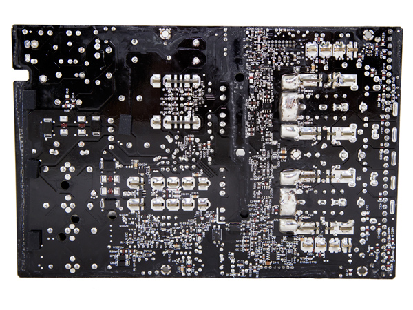
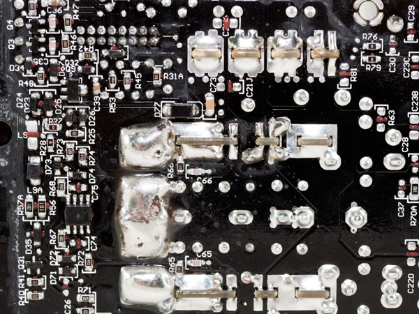
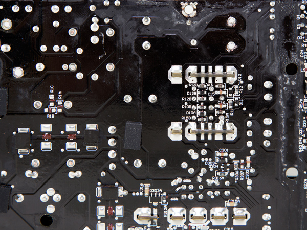
In general, the soldering quality is good, although we noticed some minor issues with it. The finish of the PCB could be better in some spots as well. We also believe it would be better if Super Flower used a thicker PCB featuring more layers.
Super Flower uses the same fan on most of its products, so in this unit, we found the usual fan by Globe Fan with model number RL4Z-B1402512EH (140mm, 12V, 0.6A, 2000 RPM, 153.47 CFM, 39.5 dB[A], 70,000-hour MTBF). This fan has double ball bearings for an increased life span, and it can be very loud when it rotates at full speed. Thankfully, the fan profile is far from aggressive, so you will have to push the PSU really hard, as we did, to make the fan spin at its max RPMs.
Current page: A Look Inside And Component Analysis
Prev Page Packaging, Contents, Exterior And Cabling Next Page Load Regulation, Hold-Up Time And Inrush Current
Aris Mpitziopoulos is a contributing editor at Tom's Hardware, covering PSUs.
-
Shankovich As much as these super powered PSU reviews are interesting, I wouldn't mind seeing more PSU's for the regular non 4-way Crossfire/SLI user. I think in July you guys did some 450W reviews? Wouldn't also mind a battle of the basement review for those cheap PSU's just for fun. Again, love these 1000+ Watt reviews, but maybe toss in some sub 600W stuff in there more often if possible. Love the depth you guys go to in your PSU reviews!Reply -
MasterMace The Power Supply failed 80 Plus Titanium specifications at 50% (93.34% vs 94%) and 100% (89.61% vs 90%)Reply -
tanjo Page 9 graphs shows a different PSU (Corsair CS850M) though they all link to the correct full list images when clicked.Reply -
ko888 Reply15706850 said:The Power Supply failed 80 Plus Titanium specifications at 50% (93.34% vs 94%) and 100% (89.61% vs 90%)
80 PLUS certification occurs at 23°C only.
Tom's Hardware is testing in a hotbox at over 42°C. So how is that failing 80 Plus Titanium specifications when 80 PLUS Organization doesn't certify or even test at that temperature?
Kitguru.net measures efficiency at 35°C and the SuperFlower Leadex Titanium 1600W has no problem meeting 80 PLUS Titanium:
http://www.kitguru.net/components/power-supplies/zardon/superflower-leadex-titanium-1600w-review/6/ -
alidan ReplyAs much as these super powered PSU reviews are interesting, I wouldn't mind seeing more PSU's for the regular non 4-way Crossfire/SLI user. I think in July you guys did some 450W reviews? Wouldn't also mind a battle of the basement review for those cheap PSU's just for fun. Again, love these 1000+ Watt reviews, but maybe toss in some sub 600W stuff in there more often if possible. Love the depth you guys go to in your PSU reviews!
i personally cant see a reason to go lower than 650 watts, the most basic computer with a gpu may only use 50-60% of it at load, but the head room is valued by me far more than the cheaper outset cost...
i had a psu blow up on me... never again. -
Aris_Mp ReplyAs much as these super powered PSU reviews are interesting, I wouldn't mind seeing more PSU's for the regular non 4-way Crossfire/SLI user. I think in July you guys did some 450W reviews? Wouldn't also mind a battle of the basement review for those cheap PSU's just for fun. Again, love these 1000+ Watt reviews, but maybe toss in some sub 600W stuff in there more often if possible. Love the depth you guys go to in your PSU reviews!
As much as these super powered PSU reviews are interesting, I wouldn't mind seeing more PSU's for the regular non 4-way Crossfire/SLI user. I think in July you guys did some 450W reviews? Wouldn't also mind a battle of the basement review for those cheap PSU's just for fun. Again, love these 1000+ Watt reviews, but maybe toss in some sub 600W stuff in there more often if possible. Love the depth you guys go to in your PSU reviews!
As much as these super powered PSU reviews are interesting, I wouldn't mind seeing more PSU's for the regular non 4-way Crossfire/SLI user. I think in July you guys did some 450W reviews? Wouldn't also mind a battle of the basement review for those cheap PSU's just for fun. Again, love these 1000+ Watt reviews, but maybe toss in some sub 600W stuff in there more often if possible. Love the depth you guys go to in your PSU reviews!
The next PSUs will be more down to earth, with sub-1000 W capacities
-
Aris_Mp ReplyThe Power Supply failed 80 Plus Titanium specifications at 50% (93.34% vs 94%) and 100% (89.61% vs 90%)
Page 9 graphs shows a different PSU (Corsair CS850M) though they all link to the correct full list images when clicked.
Already informed the editors responsible to fix this. Thanks!
