LG W2452V 24-Inch Monitor Tear-Down And Repair
The 5V Supply
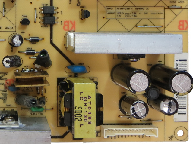
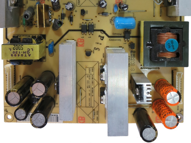
This board's bottom-right area is almost entirely dedicated to the 5V supply. There are no discrete external transistors here. The chip under that thick U-shaped copper sink is driving the 5V transformer directly. Based on the silkscreen, the output can provide up to 3A.
The two larger caps are the ones I replaced during my original repair. They're on the 5V rail, as is the smaller original cap on the left. The bulging small cap to the right is on the 12V output and I did not bother replacing it originally, since it still looked fine back then.
About That Heatsink
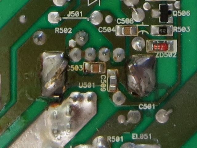
If you want to see the chip hidden under that copper heat-sink, you need to wick the solder off and straighten the pins holding it down. Since I still use the W2452V as my primary display, I would rather not risk going that far.
I have looked at a bunch of DIP-7 off-line standby PWMs from various vendors to find what this chip might be, and the closest probable match I found for this wiring configuration was Sanken's STR-A60xxH.
The 12V And 24V Rails
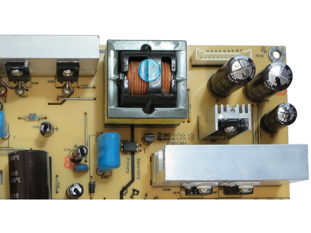
This is where I ran out of spare parts during my first repair effort. The two larger caps in the top-right corner provide the 24V required by the CCFL inverter board. The crustier capacitor on the left had one of the largest mounds of dried-out electrolyte I had ever seen on a cap, but I accidentally knocked it off before taking a picture. The smaller cap below them is on the 12V rail and also looks like it has seen better days.
These two output rails are regulated by the ST L6599D resonant-mode controller on the bottom with help from the two MOSFETs on the heat sink to drive the transformer and its series resonant capacitor.
Going Close-Up
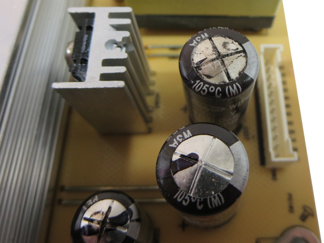
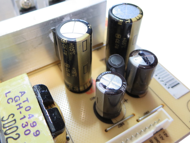
Since the previous image does not do justice to how crusty that capacitor's top is, here is a different angle. Before I accidentally knocked it off, the pile of dried black electrolyte formed a nearly perfect cone roughly 10mm tall covering the whole metal top.
Get Tom's Hardware's best news and in-depth reviews, straight to your inbox.
Those of you who know their bad caps might recognize these from the infamous Samwha WB series, which was allegedly discontinued in 1999 but found its way back into products manufactured in 2007-2008. Somehow, they still appear readily available on the Shenzen market, even today.
The Last Centurion
The third and only pristine-looking original cap on the 5V rail (bottom-left) is connected downstream from the large caps and inductor, isolating it from most switching noise. This goes to show you that even “bad caps” can last quite a while when they're not exposed to harsh current waveforms.
Curiously enough, the footprint tells us that a fatter, presumably beefier capacitor was originally intended to go in this low-stress location.
Meet The Family
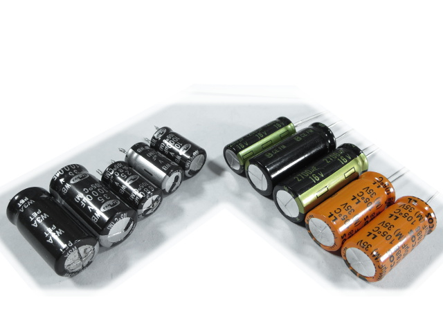
One often overlooked capacitor specification is ripple current rating. Based on the Samwha WB specs I managed to find, the 35V 1000µF caps are rated for a respectable 2.7A, the 25V 680µF for a more modest 1.8A and the 10V for a wimpy 1A. I will be replacing them with 35V 1000µF Epcos B41888 rated for 2.4A, 16V 2700µF Panasonic FM rated for 3.6A and 16V 1200µF FM rated for 2.5A.
Will the Epcos' slightly worse specifications on paper bite me in the rear a few years down the line or will higher quality prevail with more graceful aging?
Patched Up
There we go; the caps look much better without those bulgy tops. Is it just me or does the board look much sexier now?
Rigged For Testing
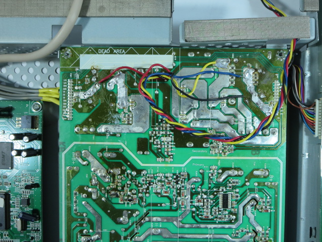
Before I can turn the monitor on to take any measurements, I have to almost completely re-assemble it. Since I cannot access the PCB once the panel is back on, I had to solder wires and bring the rails out. I mention this now because long wires will introduce common-mode noise, making switching transients look much worse than they actually are. In other words, try to ignore the high-frequency ringing and spikes.
Let's Have Some Results
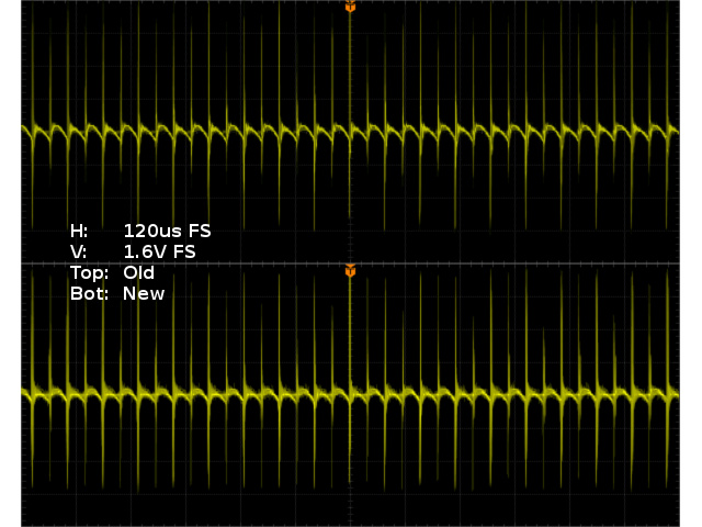
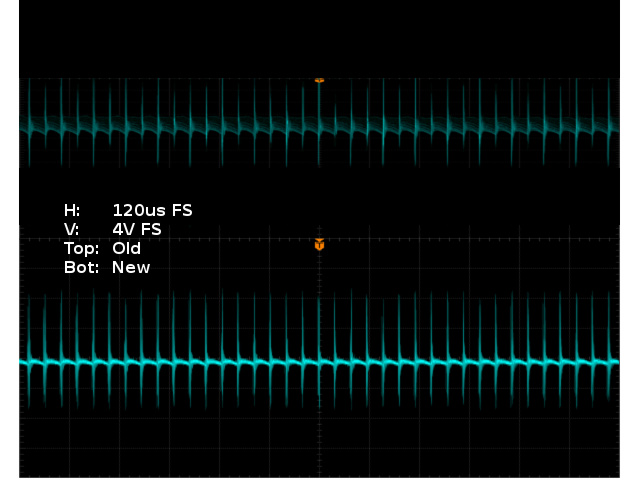
Since the graticule is nearly invisible after scaling oscilloscope screen caps to fit two in a single image with matching scales, I traded the normal “per division” vertical scale for a “Full Scale”, which applies to individual image halves.
Going from 680µF to 1200µF on the last original 5V cap did not have a big impact. The ripples look marginally better, while the fuzzier lines are caused by slightly worse ringing, courtesy of the new cap's lower ESR providing less damping.
Something More Encouraging
It looks like more of the same on the 12V rail. I replaced the cap closest to the rectifiers with a 2700µF and the second cap with a 1200µF, roughly tripling total rail capacitance. Ripples are halved at best, but ringing also increases noticeably from the decreased ESR.
As shocking as it may sound, the two leaky, bulgy Samwhas on the 12V rail were still getting the job done about as well as my new super-sized caps.
-
iam2thecrowe I normally find in Samsung monitors a Samxon capacitor leaking. I swear monitor manufacturers put them in on purpose as a time-bomb capacitor. They fail after about 5 years, long enough that you thought, ok well i had a good run, but not short enough that it is an early failure. Its good to see an article like this, many monitors can be saved this way if you have a little soldering skill.Reply -
coolkwc Bad cap again...the cheapest yet effective time bomb of all components. Seldom got ppl want to dismantle dead old monitor even they have solder skill, simply because dismantle process before you can access to that tiny component itself already stopped alot of ppl ambitious. So i say this is effective time bomb to kill the device.Reply -
iam2thecrowe Reply15491836 said:Bad cap again...the cheapest yet effective time bomb of all components. Seldom got ppl want to dismantle dead old monitor even they have solder skill, simply because dismantle process before you can access to that tiny component itself already stopped alot of ppl ambitious. So i say this is effective time bomb to kill the device.
I generally have no problem getting anything apart and it only takes a few minutes. But yea i agree with this a little, a HP monitor i recently tried to fix was held together with noting but plastic clips, it was not designed to be taken apart once assembled. The plastic clips often break and they don't go back together 100%. -
crmaris When you want to check which capacitor is preventing a PSU (embedded in a device or a standalone) from starting try heating the ones that look defective with the heating iron. The bad cap once heated will allow the PSU to start and then you will know which one is bad.Reply
If you want a more scientific way then you should get an ESR meter. I have seen many caps that weren't bulged but still were bad (high ESR). -
coolkwc Basically none of them except those 'audiophile' equipment and PC component hear about our rant over internet/forum about badcap. Consumer product they often use dirt cheap component to maximize their profit. Nowadays especially those Japanese and Korean brand, they just provide design, and left manufacturing process (material decision) to those China maker, so basically Japanese and Korean device = China brand. A good example is Panasonic product never use a single piece of capacitor from its own brand or any other Japanese brand despite the fact that its capacitor is highly reputable. What a shame.Reply -
Daniel Sauvageau Reply
To use an ESR meter properly, you have to remove the caps from the circuit first and that's half of the replacement job for a cap you are already suspecting might be bad to start with. I went with the "targets of opportunity" strategy there: I'm already elbows-deep into this thing, might as well replace all potential suspects while I am in there instead of discovering a few more years down the road that another one that I skipped decided to go bad.15491955 said:If you want a more scientific way then you should get an ESR meter. I have seen many caps that weren't bulged but still were bad (high ESR).
If you paid someone $75-100 to repair an LCD, would you risk having to pay for having it repaired again 3-4 years due to skipping a $5 ($1 part + $4 time) opportunistic part replacement?
As far as the caps from my previous repair in this monitor go, I would be really surprised if they went bad without external signs since Panasonic is a far more reputable capacitor brand and the caps I used have much better specs than Samwha's. I repaired a bunch of PSUs using Panasonic FM-series caps and none of them have as far as I know.
If I had an ESR/ESL meter, I might have pulled one out just to see how the three years used FMs compare against fresh ones.
The most difficult part is prying the bezel off to remove the LCD from its enclosure. That part alone took me about an hour the first time since I did not know what sort of snap arrangement was used and there were no broken snaps to give me easier starting points. When I opened it up to do finish the repair this time around, I could have been in and out in about an hour, were it not for the hours spent taking photos for the tear-down.15492329 said:Nice article. How much time did you spend repairing it?
The repair itself only takes a few minutes once you have access to the PCB when you have a strong suspect before you even open the device and are going straight for it before investigating anything else.
-
cats_Paw ReplyI normally find in Samsung monitors a Samxon capacitor leaking. I swear monitor manufacturers put them in on purpose as a time-bomb capacitor. They fail after about 5 years, long enough that you thought, ok well i had a good run, but not short enough that it is an early failure. Its good to see an article like this, many monitors can be saved this way if you have a little soldering skill.
Em... yeah its called Planned obsolescence, nothing new, just another way most people are getting F'ed and dont know it. -
razor512 Many monitors now use lower quality capacitors in order to shorten the lives.Reply
Some will even design the boards around a more difficult repair, for example acer likes to sometimes completely flatten the leads against the PCB before soldering, thus it becomes annoying to desolder.
Here is the repair I did on my acer x191w a while back https://www.youtube.com/watch?v=hLbSbhvTTgY
PS, even on some relatively high quality brands, you will often fine a few cheap capacitors used in order to shorten the life of the panel.
The same also applies to many HDTV's
If the capacitors do not have the leads completely bent, then you are looking at about 40 seconds to a minute to replace each bad capacitor, if they are bent, then it takes much longer because there is always a little bit of solder left over, and you do not want to pull, even if you see a tiny bit as you do not want to damage the solder pads.
While the companies know that some people will do a repair them self, they know that the vast majority of people will not want to do the repair them self. Thus using a design that is is centered around being harder to fix, will prevent them from going to a 3rd party repair service, as the work involved will make the repair costs too high to justify it as compared to just getting a new device. -
JayTs Years ago my Acer monitor died after only 18 months, and I did a repair like this one. I had never opened a flat screen monitor and was amazed at the cheap construction, being held together by wimpy plastic clips and sticky tape. I found failed capacitors and decided to replace all of the caps with high-quality Nichicons. Four years later, the monitor is still working perfectly, running about 16 hours per day.Reply
For anyone who wants to try this type of repair, you need to know the following specs of each capacitor:
1. Capacitance (microfarads or uF). Match or exceed the original.
2. Rated voltage. Match or exceed the original.
3. Diameter and length. You may use a different size if you are sure it will fit.
4. Lead spacing. Measure the distance between the leads from the cap or holes in the PCB.
As explained in the article, capacitors in the power supply should be chosen to handle high ripple current and/or low ESD as necessary.
Once you have the information, it's complicated but not too difficult to find replacements at Mouser, Digi-Key, or other reputable electronic component distributors. Pick a top brand like Panasonic, Nichicon (my two personal favorites). Look for "Aluminum Electrolytic Capacitors - Leaded" or similar.
To replace all of the capacitors in my monitor, I spent about $15.
With good quality capacitors, how long can a monitor last? Who knows?
