LG W2452V 24-Inch Monitor Tear-Down And Repair
CCFL Connections
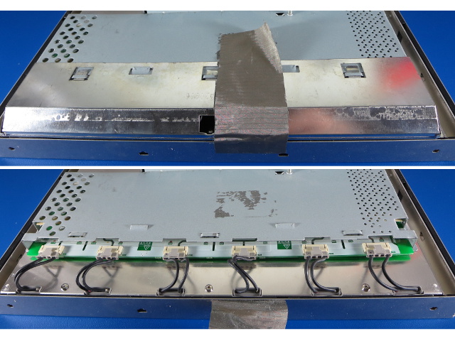
Here are those CCFL power connections with the shield on and off. If you ever pop one of these open and need to do live testing on it, keep in mind that CCFL lamps may have start-up or “striking” voltages in the neighborhood of 3kV. That's enough for a nasty zap or potentially ruined test equipment.
Lifting The Tray
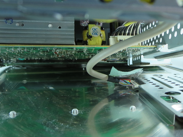
When you are ready to pop the electronics bay off the LCD's back, be mindful of the LVDS cable connecting the panel to the display controller. The wires are thin and the end connector is a thin low-force affair with tiny locking hooks.
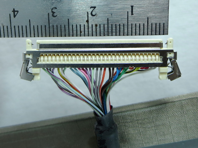
And When I Say Tiny...
The only things between you and this connector coming loose from a fair shake are two tiny hooks about half a millimeter tall, which retract when the levers are squeezed in. These won't respond well to getting accidentally yanked out. The wires themselves won't tolerate much abuse either.
Behind The Looking Glass
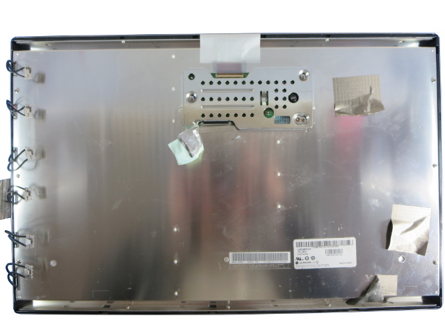
Here is the display panel liberated from the electronics bay. The CCFL power cables are flapping in the breeze along the left edge, and there is a small PCB hidden behind the perforated shielded area near the top. Practically all of the LCD's rear surface area is covered with a thin sheet of stainless steel to shield the electronics and CCFLs from each other. It may (or not) double as a reflector-diffuser for the backlight, but I have no intention of finding out before the lamps die.
Keep On Trucking
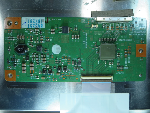
This board has two functions. On the left, we have a TI TPS65165 LCD bias regulator that provides the three voltages needed by the panel driver itself. And on the right, hidden under a thick thermal pad, is some sort of LVDS repeater. Nearly all unused space on this board is filled with via stitching to help disperse heat and noise.
At the bottom, you can see the flat-flex cable start on its way towards the panel's controller, covered with reinforcing tape to protect it from damage until it disappears under the steel sheet.
Inside The Bay
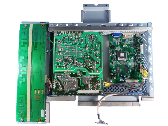
Detached from the display panel, the electronics bay can be flipped over. From the left, we see the CCFL inverter, the power supply and the display controller boards. The tray's top and bottom edges are lined with EMI gasket strips. There is not much wasted space in here.
Get Tom's Hardware's best news and in-depth reviews, straight to your inbox.
The Inverter Board
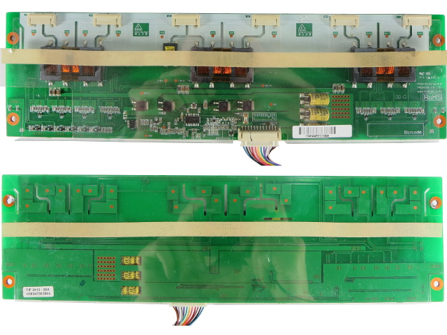
The LCD's six CCFL tubes are powered by three transformers with two secondary windings each. All three of them are driven in parallel by a full bridge of Anpec APM4008 N-FETs controlled by an MPS MP1038 CCFL controller. Since half of the board is high-voltage, it is covered by a glued-down plastic sheet on both sides to prevent arcing to the metal chassis. Three Sam Young NXH 35V 220µF caps are bent over into PCB cut-outs and still appear to be in mint condition after six years of frequent use.
No problem so far; everything still looks as good as new.
Outsourcing
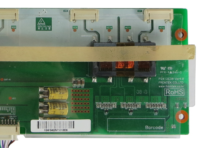
It looks like LG grabbed an off-the-shelf CCFL inverter from Frontek Co. Information on the company and its products is sparse, and the website listed on the PCB appears to be gone. The date code, just below the transformer, identifies the PCB as manufactured during the 13th week of 2008, which makes it a month shy of seven years old at tear-down time.
Further below the transformer, you can see three groups of components (resistors, capacitors and diodes) with traces running over to the high-voltage side. There is more of the same going on at the other board end. What do you suppose those might be for?
The Display Control Board
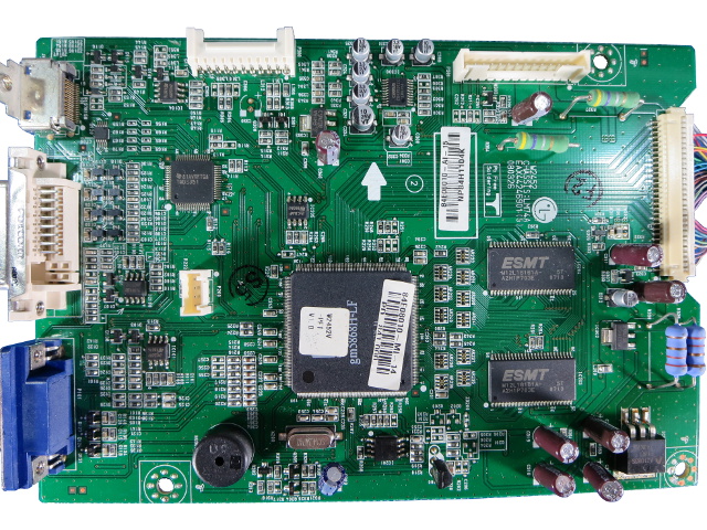
From the left, we have the HDMI, DVI and VGA inputs. DVI and HDMI pass through a signal switch before reaching the display controller IC. The small IC surrounded by caps is the DAC feeding the audio output jack, while the right third of the board contains nothing noteworthy aside from two DRAM chips and the LVDS connector.
I scratched my head for a few seconds when I noticed the speaker near the bottom-left. But then I remembered that turning off UI sounds (and the start-up jingle by extension) was one of the first things I did after turning the display on for the first time.
Quick Look From Behind
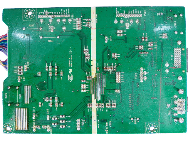
Before proceeding with a more detailed tour of the board, let's take quick lookat its back. Like many surface mount boards, the majority of interesting components are on top, while the bottom hosts mostly passive parts that wouldn't fit up there. In this case, you'll mostly find power decoupling caps. Light-brown flux residue is present all over the board.
If you didn't already guess, the areas with solder strips are simply heat spreaders for two of the linear regulators and the display controller itself. All power on this board appears to come from linear regulators.
-
iam2thecrowe I normally find in Samsung monitors a Samxon capacitor leaking. I swear monitor manufacturers put them in on purpose as a time-bomb capacitor. They fail after about 5 years, long enough that you thought, ok well i had a good run, but not short enough that it is an early failure. Its good to see an article like this, many monitors can be saved this way if you have a little soldering skill.Reply -
coolkwc Bad cap again...the cheapest yet effective time bomb of all components. Seldom got ppl want to dismantle dead old monitor even they have solder skill, simply because dismantle process before you can access to that tiny component itself already stopped alot of ppl ambitious. So i say this is effective time bomb to kill the device.Reply -
iam2thecrowe Reply15491836 said:Bad cap again...the cheapest yet effective time bomb of all components. Seldom got ppl want to dismantle dead old monitor even they have solder skill, simply because dismantle process before you can access to that tiny component itself already stopped alot of ppl ambitious. So i say this is effective time bomb to kill the device.
I generally have no problem getting anything apart and it only takes a few minutes. But yea i agree with this a little, a HP monitor i recently tried to fix was held together with noting but plastic clips, it was not designed to be taken apart once assembled. The plastic clips often break and they don't go back together 100%. -
crmaris When you want to check which capacitor is preventing a PSU (embedded in a device or a standalone) from starting try heating the ones that look defective with the heating iron. The bad cap once heated will allow the PSU to start and then you will know which one is bad.Reply
If you want a more scientific way then you should get an ESR meter. I have seen many caps that weren't bulged but still were bad (high ESR). -
coolkwc Basically none of them except those 'audiophile' equipment and PC component hear about our rant over internet/forum about badcap. Consumer product they often use dirt cheap component to maximize their profit. Nowadays especially those Japanese and Korean brand, they just provide design, and left manufacturing process (material decision) to those China maker, so basically Japanese and Korean device = China brand. A good example is Panasonic product never use a single piece of capacitor from its own brand or any other Japanese brand despite the fact that its capacitor is highly reputable. What a shame.Reply -
Daniel Sauvageau Reply
To use an ESR meter properly, you have to remove the caps from the circuit first and that's half of the replacement job for a cap you are already suspecting might be bad to start with. I went with the "targets of opportunity" strategy there: I'm already elbows-deep into this thing, might as well replace all potential suspects while I am in there instead of discovering a few more years down the road that another one that I skipped decided to go bad.15491955 said:If you want a more scientific way then you should get an ESR meter. I have seen many caps that weren't bulged but still were bad (high ESR).
If you paid someone $75-100 to repair an LCD, would you risk having to pay for having it repaired again 3-4 years due to skipping a $5 ($1 part + $4 time) opportunistic part replacement?
As far as the caps from my previous repair in this monitor go, I would be really surprised if they went bad without external signs since Panasonic is a far more reputable capacitor brand and the caps I used have much better specs than Samwha's. I repaired a bunch of PSUs using Panasonic FM-series caps and none of them have as far as I know.
If I had an ESR/ESL meter, I might have pulled one out just to see how the three years used FMs compare against fresh ones.
The most difficult part is prying the bezel off to remove the LCD from its enclosure. That part alone took me about an hour the first time since I did not know what sort of snap arrangement was used and there were no broken snaps to give me easier starting points. When I opened it up to do finish the repair this time around, I could have been in and out in about an hour, were it not for the hours spent taking photos for the tear-down.15492329 said:Nice article. How much time did you spend repairing it?
The repair itself only takes a few minutes once you have access to the PCB when you have a strong suspect before you even open the device and are going straight for it before investigating anything else.
-
cats_Paw ReplyI normally find in Samsung monitors a Samxon capacitor leaking. I swear monitor manufacturers put them in on purpose as a time-bomb capacitor. They fail after about 5 years, long enough that you thought, ok well i had a good run, but not short enough that it is an early failure. Its good to see an article like this, many monitors can be saved this way if you have a little soldering skill.
Em... yeah its called Planned obsolescence, nothing new, just another way most people are getting F'ed and dont know it. -
razor512 Many monitors now use lower quality capacitors in order to shorten the lives.Reply
Some will even design the boards around a more difficult repair, for example acer likes to sometimes completely flatten the leads against the PCB before soldering, thus it becomes annoying to desolder.
Here is the repair I did on my acer x191w a while back https://www.youtube.com/watch?v=hLbSbhvTTgY
PS, even on some relatively high quality brands, you will often fine a few cheap capacitors used in order to shorten the life of the panel.
The same also applies to many HDTV's
If the capacitors do not have the leads completely bent, then you are looking at about 40 seconds to a minute to replace each bad capacitor, if they are bent, then it takes much longer because there is always a little bit of solder left over, and you do not want to pull, even if you see a tiny bit as you do not want to damage the solder pads.
While the companies know that some people will do a repair them self, they know that the vast majority of people will not want to do the repair them self. Thus using a design that is is centered around being harder to fix, will prevent them from going to a 3rd party repair service, as the work involved will make the repair costs too high to justify it as compared to just getting a new device. -
JayTs Years ago my Acer monitor died after only 18 months, and I did a repair like this one. I had never opened a flat screen monitor and was amazed at the cheap construction, being held together by wimpy plastic clips and sticky tape. I found failed capacitors and decided to replace all of the caps with high-quality Nichicons. Four years later, the monitor is still working perfectly, running about 16 hours per day.Reply
For anyone who wants to try this type of repair, you need to know the following specs of each capacitor:
1. Capacitance (microfarads or uF). Match or exceed the original.
2. Rated voltage. Match or exceed the original.
3. Diameter and length. You may use a different size if you are sure it will fit.
4. Lead spacing. Measure the distance between the leads from the cap or holes in the PCB.
As explained in the article, capacitors in the power supply should be chosen to handle high ripple current and/or low ESD as necessary.
Once you have the information, it's complicated but not too difficult to find replacements at Mouser, Digi-Key, or other reputable electronic component distributors. Pick a top brand like Panasonic, Nichicon (my two personal favorites). Look for "Aluminum Electrolytic Capacitors - Leaded" or similar.
To replace all of the capacitors in my monitor, I spent about $15.
With good quality capacitors, how long can a monitor last? Who knows?
