Silverstone SST-EP03 Tear-Down
Front Cover
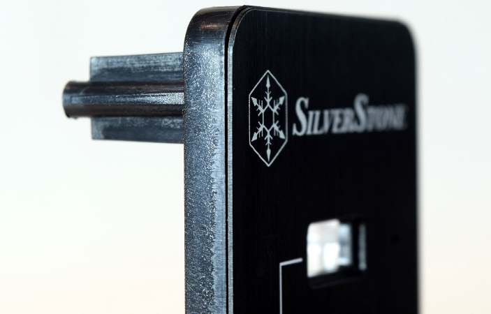
How much aluminum is in there? Look at the thin vertical line between the plastic structure with the screw mount on the left and the front with SilverStone’s logo on it. The aluminum sheet is less than half a millimeter thick and entirely cosmetic in function: it provides a somewhat scratch-resistant surface to stab with Type A connectors. The brushed finish also helps hide fingerprints and scratches.
I was expecting more aluminum from a “high-quality brushed aluminum design” than this thin scratch shield laminated on top of a plastic structure.
MORE: Best PC Builds
MORE: Best Cases
PCB Top
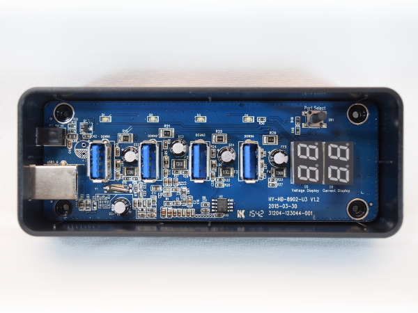
The top of the board looks crowded along the center line with a bunch of passive components crammed between each USB port up to the LED displays. The upper area looks under-utilized, while the bottom-left area is populated with what looks like power-related components and a fifth capacitor.
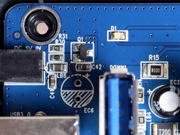
From this angle, the first thing that drew my attention was the vacant capacitor footprint next to the DC-in jack, no doubt intended for a sixth capacitor.
MORE: Best Deals
Get Tom's Hardware's best news and in-depth reviews, straight to your inbox.
MORE: Hot Bargains @PurchDeals
Light Pipes
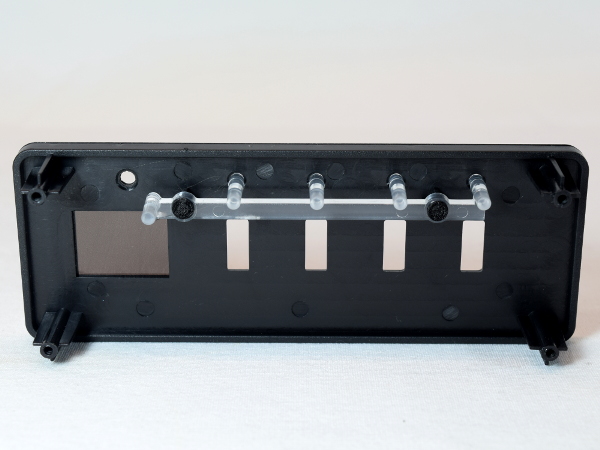
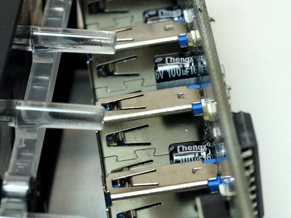
How do you cover the distance from the LEDs on the board to those tiny holes in the aluminum front piece? One option would be mounting the LEDs on supports and shaping holes under the cover to guide them into place. But SilverStone went with light pipes, clear or slightly diffuse pieces of plastic to guide light from its source to wherever it is needed. To save manufacturing steps, the four light pipes are molded as one piece and joined by a side strip to minimize leakage between pipes.
If you look closely, you can also see multiple injection molding tooling holes on the cover’s inner face.
MORE: Best Power Supplies
MORE:10 Inexpensive Automotive USB Adapters Tested
Crystal Twister
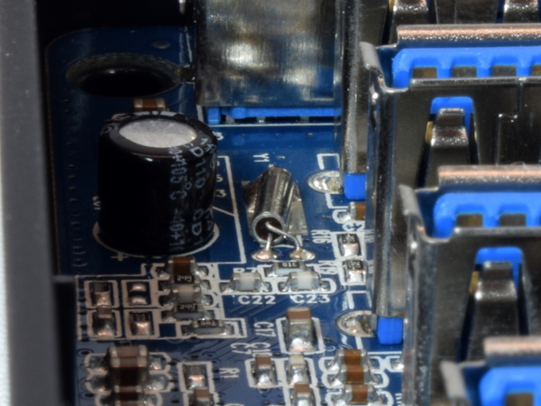
It looks like the crystal can is playing Twister with itself, with one leg bent at odd angles over the other to reach its pad. The crystal must have been put in crooked and bent over the board to solder its body to the PCB for mechanical support, causing the longer leg to twist over like this.
I don't see this style of crystal very often, as most manufacturers favor surface-mount equivalents that are readily compatible with pick-and-place machines for automated assembly.
MORE: Best PC Builds
MORE: Best Cases
Curious Little Thing
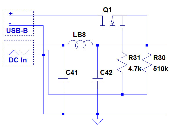
What does that little circuit around the DC input jack and omitted EC6 do? At first, I thought that Q1 was set up as an ideal rectifier and soft-switch circuit to prevent the hub’s host-provided power and capacitors from getting dumped into an unpowered adapter. A few measurements told a slightly different story, though.
MORE: Best Deals
MORE: Hot Bargains @PurchDeals
How Does That Work?
The principle is simple: the barrel jack has an extra normally-closed switch contact on the shell contact. With no AC adapter plugged in, the FET’s gate gets grounded by the barrel switch and allows power from the USB host to feed the hub. When the external adapter is plugged in, it breaks the normally closed contact, the gate gets charged to 5V, and the FET stops conducting, disconnecting the USB host's power feed. Circuitry of this sort is necessary to prevent USB hub power from back-feeding into the host where it can cause issues like preventing a PC from shutting down.
In this configuration, the host may still end up providing power through the FET’s body-diode if the adapter’s voltage sags to one diode drop (~0.5V) below the USB cable’s voltage.
MORE: Best Power Supplies
MORE:10 Inexpensive Automotive USB Adapters Tested
High Rise
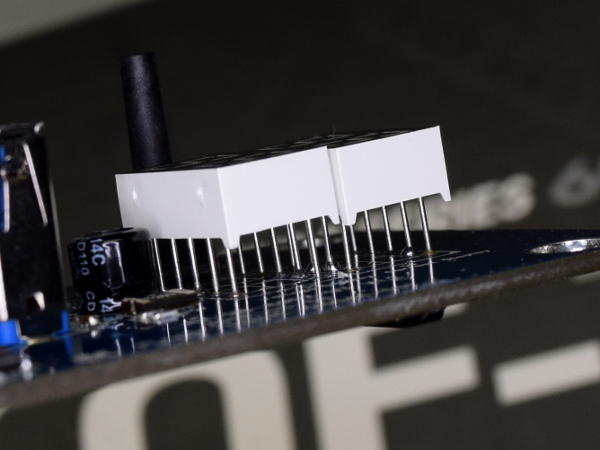
It looks like my guess about the seven-segment LEDs requiring additional height was partly correct. Instead of sockets or extensions of some sort, the design may have been meant for use with even longer-leaded free-standing modules.
MORE: Best PC Builds
MORE: Best Cases
Chengx For Everyone
What sort of electrolytics are in there? They are all Chengx 100µF 16V capacitors. The brand isn't one of our favorites, but without any significant heat sources or a switching power supply nearby, and all five of them in parallel to share whatever they may get exposed to, these shouldn't see much ripple current. They're suitable for the application.
MORE: Best Deals
MORE: Hot Bargains @PurchDeals
Between Sockets
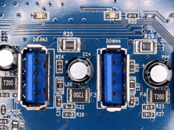
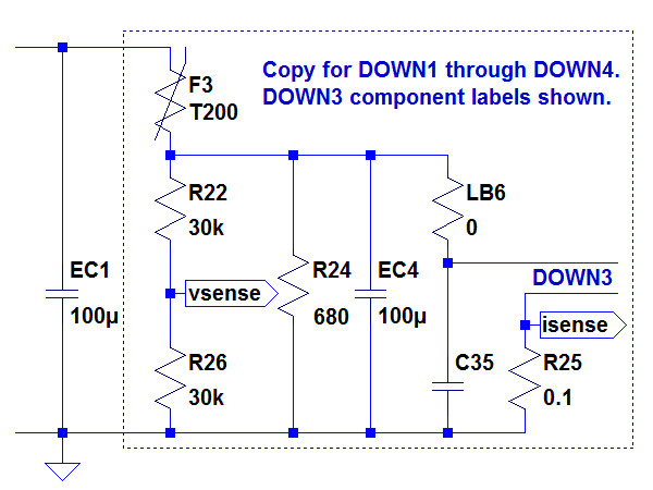
What is the circuitry replicated between sockets for? From the top, each downstream port has a 0.1Ω low-side current-sensing resistor, its own Chengx local bypass capacitor, a 680Ω bleeder resistor, a 0Ω resistor in place of a ferrite bead inductor, a 2A PTC fuse on the high side, a tiny multi-layer chip capacitor, and a pair of 30kΩ resistors.
MORE: Best Power Supplies
MORE:10 Inexpensive Automotive USB Adapters Tested
What This Translates To
To reach individual ports, power from the internal 5V rail passes through the PTC fuse, gets locally bypassed by the electrolytic and ceramic capacitors (EC4 and C35), passes through the 0Ω resistor that was originally intended to be an inductor, the device, and finally, the 0.1Ω current sense resistor to ground. The two 30kΩ resistors form a voltage divider to sense each port’s voltage after the fuse, which explains how the voltage meter can have a range of 0-5.5V. The output can drop close to 0V after the PTC fuse (F3) heats up enough to cut the port off.
I see no reason to waste 40mW on a bleeder resistor (R24). It may have been meant to dampen oscillations between C35, LB6, and EC4. Those won’t happen with a 0Ω resistor substituted for LB6, though.
MORE: Best PC Builds
MORE: Best Cases
-
Daniel Sauvageau Many people say that reviewers get cherry-picked samples. As my contact at Silverstone told me when I sent him a copy of my tear-down as a heads-up for what was coming, reviewers get whatever inventory is in the warehouse like everybody else and I doubt anybody will dispute that here.Reply -
itsnotmeitsyou This was awesome. Thanks for this kind of content TH. Makes this feel like a real technically oriented website instead of just tech gossip. Kinda felt like that was where things were headed for a while.Reply -
jtd871 Good on SilverStone for asking for your unvarnished criticism. But it's disappointing that SS's own QA/QC doesn't pick up these issues.Reply -
Daniel Sauvageau Reply
Most of these were more 'quibbles' than serious issues though: as long as the flux is non-corrosive at room temperature, there is nothing technically wrong with leaving the finished PCB drowned in it. Solder blobs may not be pretty but as long as they don't touch anything they shouldn't, there is nothing wrong with those either. Ripples and noise on VBus may not be pretty but section 11.4.4.2 of the USB 3.1 spec (VBus) does not have a noise or ripple specification. Anything from 4.45V to 5.25V appears to be fair game.18896400 said:Good on SilverStone for asking for your unvarnished criticism. But it's disappointing that SS's own QA/QC doesn't pick up these issues.
The only real issue I have with it is the mechanical/shield hole on the upstream port since leaving one tab loose means more stress on the data pins when the cable gets (dis)connected or tugged. SilverStone told me one tab is enough, but I don't have to like it.
