QQC Q-Swap Power Bank Tear-Down
Q-Boost Open Frame
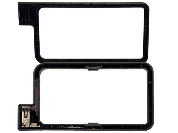
Now here’s a somewhat puzzling first look at the Q-Boost frame’s internals. From the exterior shape, you may have expected the electronics to be tucked away in the connector and contact pad areas. But this picture shows the space immediately next to the type-A socket to be empty. If you pay close attention to the type-A connector and follow the PCB edge, you can see it extend into the side wall all the way to the cell retention clip.
Locating electronics into hollow walls is one way of saving space.
MORE: SilverStone PB06 USB Power Bank Tear-Down
MORE: Best Deals
Q-Boost Cell Retention
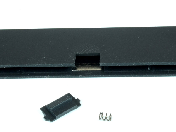
Whereas a budget-oriented manufacturer would likely have molded the retention tabs directly into the frame and relied on the frame’s flex to hold the cell in, QQC went with separate plastic tabs powered by tiny springs on each side. To top that off, a metal insert in the frame prevents the spring from eventually wearing its way through the outer wall it rests against.
As far as plastic housings go, no expense was spared here.
MORE: SilverStone PB06 USB Power Bank Tear-Down
Get Tom's Hardware's best news and in-depth reviews, straight to your inbox.
MORE: Best Deals
Q-Boost Innards
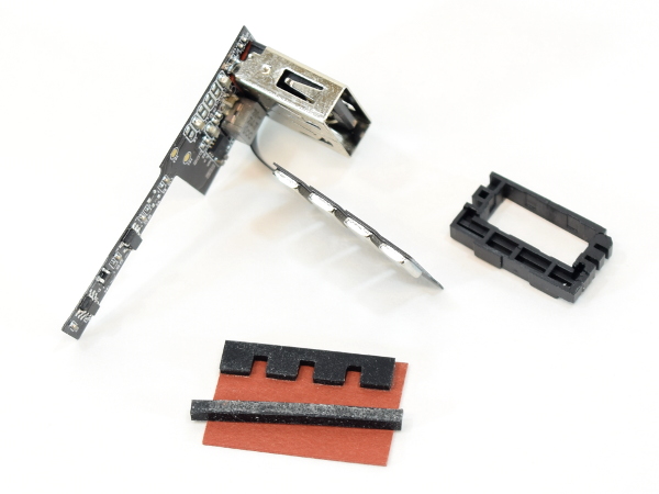
The attention to detail continues with a mechanical support frame around the type-A connector to help lock it in place, a rubber strip on a piece of phenolic cardboard to provide pressure for the cell contacts, and a thin rubber strip to hold things in place for assembly. As an interesting design twist, the Q-Boost’s circuit board is so thin that QQC could afford to build the whole thing as a single piece, then bend the board’s contact area into place to eliminate wiring between boards.
While chips on flat flex cable (FFC) are commonplace, I believe this is my first time seeing a manufacturer flex a regular (albeit thin) circuit board.
MORE: SilverStone PB06 USB Power Bank Tear-Down
MORE: Best Deals
Flattened Q-Boost
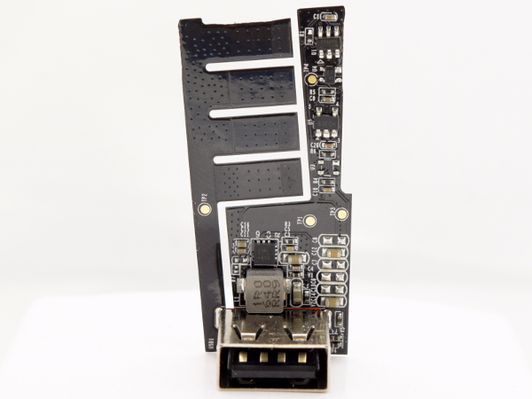
I gingerly straightened the Q-Boost’s board to have a flat look at it, as if freshly cut off from the manufacturing panel. Shockingly enough, there is next to nothing on it. We have a one-microhenry inductor next to a QFN-style 6939, which must be a boost converter with integrated drivers, an SOT25 93F04 also found in the Q-Cell, which may be a linear voltage regulator, an SOT343 ML23 that I suspect is a One-Wire device based on how the Q-Cell’s D_P signal gets routed straight to its immediate neighborhood, and a SOT26 FT4KPK that connects to the type-A port’s data lines, likely making it a charging mode detection chip. I could not find definitive matches for any of these.
I was expecting some form of processor to talk with the Q-Cell’s micro-controller.
MORE: SilverStone PB06 USB Power Bank Tear-Down
MORE: Best Deals
Q-Boost SMD Soldering
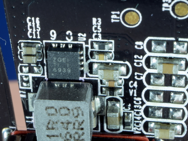
Soldering uniformity looks a lot better in the Q-Boost than the Q-Cell, with no excess solder balling up on the pads or component leads. Solder balling around the 6939 is more subtle than it was on the Q-Cell’s QFN, and the 0603/0402 components have the characteristic uniform concave filleting with full pad coverage. Did QQC use a thinner solder paste stencil for this board?
MORE: SilverStone PB06 USB Power Bank Tear-Down
MORE: Best Deals
Q-Boost Through-Hole Soldering
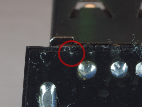
While the SMD-side soldering looked very good, the type-A connector’s soldering is slightly worse. Although the joints themselves look fine, there is leftover solder flux on the board that lint gets stuck to. And embedded in that solidified flux are a few tiny solder globules like the one circled in red, along with a smaller one further to its right. These could become a short-circuit hazard if they ever broke loose from the flux.
I doubt the Q-Frame will ever get hot enough to liquefy the flux and free the globules, but I would have preferred that they both went away in the ultrasonic cleaner.
MORE: SilverStone PB06 USB Power Bank Tear-Down
MORE: Best Deals
Missed Opportunity
I mentioned earlier that the combination of taper and different corner radii on the Q-Cell made it impossible to insert the cell incorrectly. I found one practical disadvantage to this: if you could insert the Q-Cell rotated 180° so its contacts faced away from the Q-Frame contacts, then you could use the Q-Frame as a Q-Cell contact cover, greatly reducing the risk of shorting the exposed Q-Cell contacts and eliminating the live Q-Frame type-A port when not in use.
MORE: SilverStone PB06 USB Power Bank Tear-Down
MORE: Best Deals
Q-Cell Charging Circuit
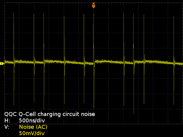
Remember how I said I’d expect the charging regulator to operate somewhere north of 1 MHz? Here I am measuring the regulator’s output ripples and there are effectively none to speak of. All we see are the chip’s very fast switching transients, which demonstrate irregular intervals as short as 300ns and as long as 1µs. There may be a feedback loop stability issue going on.
This sort of artifact is no good for efficiency due to increased transistor switching and inductor losses. That might explain the unbearably hot inductors.
MORE: SilverStone PB06 USB Power Bank Tear-Down
MORE: Best Deals
Q-Cell Output Liveliness Test
One question I brought up earlier was whether or not getting power out of the Q-Cell might be as simple as hooking it up. For safety reasons, I expected output current to be extremely limited (say, 10mA) until some sort of handshake was completed.
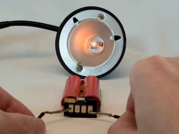
In order to determine which one was correct, I connected a 20W halogen bulb across the battery terminals and the bulb lit up to a dim orange glow, drawing 930mA in the process.
There's no secret handshake here; just remain below the over-current cut-off.
MORE: SilverStone PB06 USB Power Bank Tear-Down
MORE: Best Deals
Q-Cell Short-Circuit Behavior
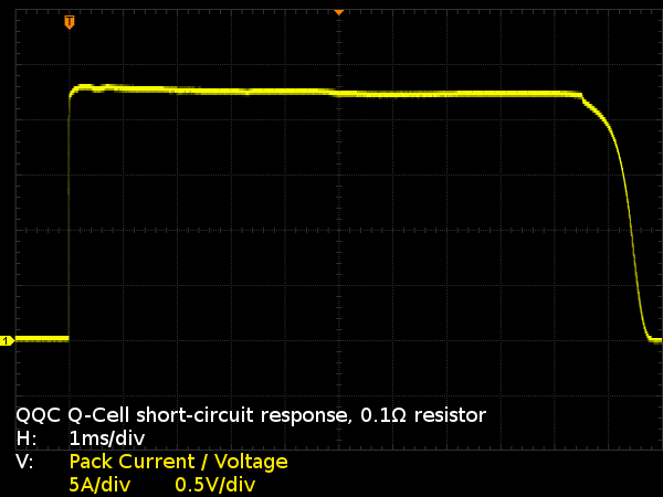
How high does the Q-Cell’s short-circuit current go, and how quickly does it disconnect its output when such a short happens? To find out, I shorted the pack’s contacts with a 0.1Ω resistor and recorded the cell’s response with an oscilloscope. Since I = V / R and R = 0.1, the current is the same as the voltage multiplied by ten. Here, we see the Q-Cell putting out roughly 22.5A for 9.5ms before cutting off its output.
At first, I thought the not-quite-vertical rise meant that the Q-Cell had some sort of current rise rate limit. Then I realized that it may simply be my ceramic wire-wound resistor acting as an inductor.
Let’s see what happens with a beefier resistor.
MORE: SilverStone PB06 USB Power Bank Tear-Down
MORE: Best Deals
-
JamsCB Interesting idea, but by going with this design of a spare battery with exposed contacts means you're going to have to do something with that extra battery if you want to fly anywhere, at least in the US (See the regulation: 49 CFR 175.10(a)(18) ). Personally I feel if you need that much spare charge, two separate banks would be the simpler and cheaper option.Reply -
sparkyman215 Asus makes a great battery pack with 10k mAh, and it's only $20. I've had mine for maybe a year and it hasn't exploded yetReply -
LostAlone Feels like this is entirely misguided on their part. Battery packs are bulk commodity items now, they've become cheap and ubiquitous. Everyone has their own branded ones out there. And with that in mind, I just don't understand an expensive version. Honestly, even in the corner case that you need so much juice that multiple battery packs are reasonable then I'd rather have another complete back with it's extra ports available. Sure, a little more bulk but only slightly and this gives me a truly redundant solution that I can lend to someone or have a complete spare in the event of loss or damage.Reply
In the end, given that battery packs are already light and small making a lighter smaller one isn't that big a deal. Any thing in the 10k mAh range is too big to keep in a pocket all day anyway, and once you're tossing the things in a bag then it really doesn't matter if it's a little big smaller or lighter. -
Daniel Sauvageau Reply
People stuff 6" 'phones' in their pockets. I've seen 10Ah power banks smaller than those but haven't tested one yet to see if they can actually deliver. I do plan to address that later this year.19802041 said:Any thing in the 10k mAh range is too big to keep in a pocket all day anyway
-
nukemaster Another good one.Reply
Looking forward to seeing your tests on some of those smaller 10Ah ones you mention. I rarely need an on the go charge(my old Zen did sometimes when I forgot to charge it), but it is always nice to have 5 volts for testing things. -
LostAlone ReplyPeople stuff 6" 'phones' in their pockets. I've seen 10Ah power banks smaller than those but haven't tested one yet to see if they can actually deliver. I do plan to address that later this year.
Phones have a bigger footprint but a 10k or 12k battery back is MUCH thicker and MUCH heavier. Take it from someone with a big phone AND a 12k battery pack; only one of those happily lives in my pocket all day. Maybe on something with cargo pockets you could stick the battery in a pocket but it wouldn't be comfortable to sit on it.
My battery pack is almost an inch thick dude; and totally inflexible and heavy enough that it can pull your pants down. It's a whole other kettle of fish compared to a phone, even a big phone. -
alextheblue I'll just shove this into my pocket with loose change...Reply
They need some kind of spring-loaded safety cover for those contacts, and at that price I would want so much more than what they're offering. Standard cylindrical cells? I would expect it to be using fancier (and higher density) packs using semi-prismatic cells or maybe higher-end well-engineered pouch cells.. Maybe support for Qi charging and higher amp output / higher volt QC capabilities. Otherwise... it's really no better than a typical 5200 pack in the $30 range. -
Daniel Sauvageau Reply
That depends heavily on the type of cells being used and by type, I mean the actual chemistry and geometry of the cell which dictate the cell's maximum charge/discharge current, cycle endurance and nominal capacity. There is a drastic energy density difference between high current, high endurance cells (thicker current-carrying electrodes and anode/cathode material) and those prioritizing energy density over all else.19805518 said:Phones have a bigger footprint but a 10k or 12k battery back is MUCH thicker and MUCH heavier.
Also, a power bank designed around pouch-style cells isn't constrained by the size of 18650 cells and can be made much thinner. -
Daniel Sauvageau Reply
Based on my limited short-circuit tests, that should actually be fine as the output cuts off within 2ms from the short being detected and wouldn't cause your change to warm up noticeably.19805743 said:I'll just shove this into my pocket with loose change...
Still, I am disappointed that there wasn't some sort of protocol between the pack and frame to limit current until the connection to an accessory is confirmed.
