11-Way P45 Motherboard Shootout
Asus Maximus II Formula
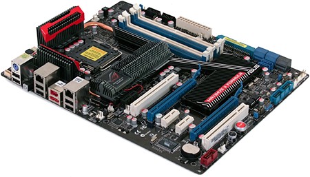
The latest in Asus’ Republic of Gamer series, the Maximus II Formula, certainly looks powerful with oversized ’sinks covering mysterious components. Many great things can be found beneath those heatsinks, but not as many as some observers had hoped. Let’s dig a little deeper.
The Maximus II Formula is not only Asus’ flagship P45 product, it’s also a showboat unto itself. Enormous ’sinks will certainly do an excellent job of cooling, and these have been designed with a removable portion that Asus may someday replace with a water cooling block (such as formerly found on the limited-edition version Maximus Formula). Sticking with the showboat theme, the ’sink’s Republic Of Gamers logo lights up, along with internal power and reset buttons. A scattering of LED’s which indicate various system problems (cards not plugged in all the way, for example) finish the theme.
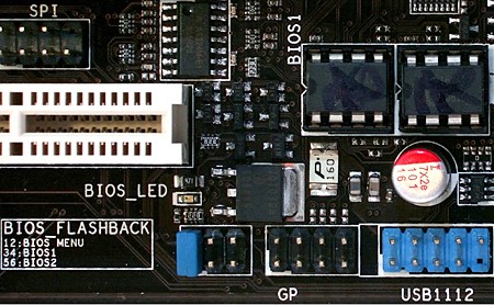
But if you’re going to show off, you’d better be good, and the Maximus II Formula is packed with features such as two PCI Express x16 slots that auto-switch between one by x16 and two by x8 modes, dual Gigabit networking, 16-phase CPU power regulation, and dual BIOS.
Starting at around $260 Web price, Asus didn’t need to make any compromises whatsoever in the design of the Maximus II Formula, and instead optimized its layout for high-speed stability and clean cable management.
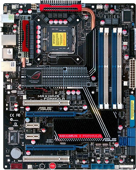
The high-speed stability optimization starts with DIMM slots that have been moved significantly “southward” to better orient them around the P45 Express northbridge. Other features have been designed around this starting point, with the top PCI Express graphics card slot in the third position.
Now, before we begin piling compliments on the Striker II Formula’s good connector layout, we thought we should address one common misconception concerning the width of the southbridge ’sink. No, it isn’t covering a PCI Express hub, especially not the rumored nForce 200. In fact, it isn’t covering anything that needs a ’sink at all. The only components that reside beside the ICH10R southbridge are the third-party ATA controller, a few electronic switches for controlling PCI Express lane width (one can already be seen next to the ’sink), a few resistors, and transistors. The huge ’sink is in fact a fake-out, made to make the Maximus II Formula fit in with several other ROG motherboards such as the Striker II Formula, Maximus Extreme, and Blitz Formula, all of which had required a PCI Express Hub to enable additional graphics card slots.
The Maximus II Formula could be viewed as a replacement for the aging Blitz Formula, a motherboard that used its PCI Express hub to split its chipset’s sixteen graphics lanes across two slots in x8 mode. The P45 Express doesn’t require additional components to do this however, as it natively supports dual graphics cards. Additional southbridge cooling could provide an excuse for this oversized part, but we know in truth it’s just for looks.
Get Tom's Hardware's best news and in-depth reviews, straight to your inbox.
The Maximus II Formula puts its 8-pin and 24-pin power connectors along the top and front edges, which make for easy cable routing to a top-mounted power supply. Builders stuck with a bottom-mounted power supply will appreciate that the 8-pin connector is close enough to the top edge to pull a cable up from behind the motherboard tray, but any cable folded over the top would cover the latch.
Asus knows that many gamers prefer Windows XP, and puts its floppy header near the top to ease cable routing in typical tower designs. The floppy is still needed by most people for adding AHCI or RAID drivers during Windows installation.
Located on the front edge, just below the motherboard’s center line, the Ultra ATA connector is probably close enough to the top bays of most mid-tower cases to run a cable to the top external bay. Users of true full towers might be a little aggravated, though oversized mid-tower users shouldn’t have a problem.
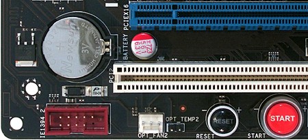
Serial ATA ports are a different matter. Designed to provide the best clearance for long graphics cards, the six forward facing ports make installation into many chassis nearly impossible, since traditional designs have a hard drive cage in close proximity to the motherboard’s front edge. Also a concern is the internal IEEE-1394 connector, with a bottom rear corner placement that often isn’t reachable by the cables of front-panel connectors.
Internal power and reset buttons are also in what appear to be an inconvenient location, but appearances are deceiving, since such buttons are only really useful for bench testing. The location of these buttons is quite handy for that intended purpose.
Current page: Asus Maximus II Formula
Prev Page P45TS-R Software And Accessories Next Page Maximus II Formula Onboard Devices-
nickchalk Where are the lower price P45 M/B ?Reply
Asus P5Q pro is out for €110 and P5Q deluxe for €165 the price difference is about 70$ in Greece. -
Proximon I suppose I can get some good from having read this. Did you get paid by the word? Maybe next time you could just put together a complete features chart so that we can have some convenient comparison? You know, so someone could go to a chart and see at a glance which boards had eSATA or firewire, or 8 USB.Reply
-
JPForums I'd rather have the overabundance of information than a lack of information. Presentation could use a little refining (I.E. comparison charts and the likes), but having the relevant information available at least is a good thing.Reply -
the introduction and specifics are nice, the comparision isn't. so, why don't you test with an 8500 or qx9650? 6850 are outdated... and a mobo handling a c2d doesn't mean it can handle a quad too, see P5K for example (it stinks when it comes to a q6600).Reply
-
Crashman procithe introduction and specifics are nice, the comparision isn't. so, why don't you test with an 8500 or qx9650? 6850 are outdated... and a mobo handling a c2d doesn't mean it can handle a quad too, see P5K for example (it stinks when it comes to a q6600).Reply
Tom's Hardware wants the performance of current articles to reflect that of recent articles, so a "standard test platform" was chosen a while ago. It will get updated, but probably not before the new socket becomes widely available. -
zenmaster I would have liked to see something such as a P35 and an X48 as controls to help analyze the P45 Performance.Reply
In otherwords, What is the P45 Gaining me over the older P35.
What would I gain by going to the X48. (Or Lose) -
Crashman zenmasterI would have liked to see something such as a P35 and an X48 as controls to help analyze the P45 Performance.In otherwords, What is the P45 Gaining me over the older P35.What would I gain by going to the X48. (Or Lose)http://www.tomshardware.com/reviews/intel-p45-chipset,1961.htmlReply -
johnbilicki The first 17 pages were filled with nothing but junk from ASUS. Do us a favor: don't even bother featuring or *MENTIONING* anything for any reason from a company that refuses to RMA 200-400 dollar brand new motherboards with anything other then used and usually broken junk. It destroyed my enthusiasm for the article.Reply -
dobby nickchalkWhere are the lower price P45 M/B ?Asus P5Q pro is out for €110 and P5Q deluxe for €165 the price difference is about 70$ in Greece.Reply
the p5q PRo is a p43 board, i should know i have one


