System Builder Marathon, June 2011: $2000 Performance PC
Hardware Installation
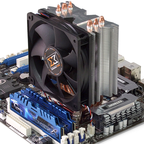
We began our installation by clipping the CPU into its interface and applying paste, as described in our How To guide. Next, we moved on to the CPU cooler.
The Xigmatek Gaia uses four long screws above the board to secure a support plate beneath it. The screws are pushed from beneath the board, up through the backplate and motherboard, and then secured with four barrel-shaped nuts. Fiber washers prevent the nuts from making contact with any motherboard circuits.
Two included brackets are then screwed to the bottom of the Gaia heat sink, and the sink drops in place with the protruding ends of the screws fitting holes in the bracket ends. Four more nuts hold the sink and brackets securely against the CPU.
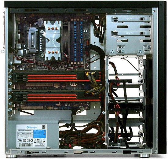
Note that we already installed the memory. This was followed by attaching the motherboard and power supply to the case. Again, both are easy-to-follow steps in the linked How To story.
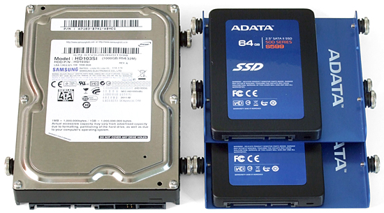
Lian-Li uses shoulder screws and rubber grommets to mount 3.5” drives on slots in the drive cage. The rubber grommets reduce noise from vibrating drives, while the screw shoulders prevent the grommets from being crushed.
A-Data’s included brackets are threaded at the sides for M3 screws, which are normally used by floppy and optical drives. Most hard drives use larger #6 UNC screws, and Lian-Li’s hard drive attachment hardware is made exclusively to this standard. Yet, because A-Data’s adapter trays are made of soft aluminum, it’s possible to force the larger screw into the smaller hole.
This actually thickens the metal surrounding the hole, making it less likely to strip (as long as it doesn’t crack). Furthermore, traditional #6 case screws have a tapered end that allows them to start in the smaller M3 holes. Rather than drill and tap the holes for the larger screws, we did what someone who didn’t own a #6-32 tap would normally try: we forced the larger screw into the smaller hole using a powered screwdriver. Of course, we didn’t want to risk damage to any of the screws that came with the case, so we used one of the left-over screws from a previous build. After opening up the holes in this manner, we installed the shoulder screws and grommets in each adapter tray.
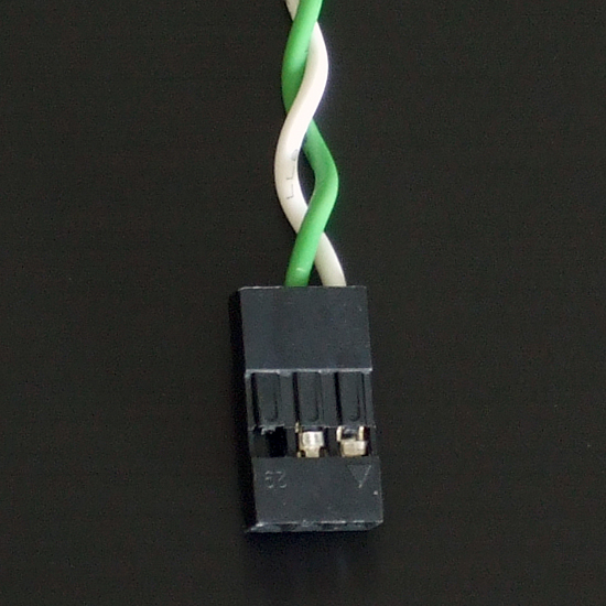
Lian-Li’s front-panel power LED is wired to an old, AT-style 3-pin connector. Nearly everyone except Asus has switched to an industry standard 9-pin layout with 2-pin spacing, including ASRock. Lifting a tab on the plastic connector released our LED connector’s positive lead, so we could move it to the center position. The excess connector could be trimmed, but we simply let it protrude past the end of our motherboard’s pin header.
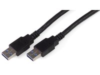
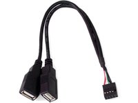
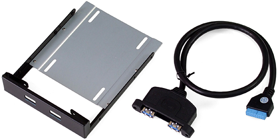
We don't particularly like that Lian-Li expects builders to chose between sloppiness or reduced functionality. The PC-9F uses external cables to connect its front-panel USB 3.0 connectors to the I/O panel through a hole in the case, leaving a loop on the back of the case that’s far too ugly to be used in a professional build. An included adapter allows builders to clean up the appearance of their system by connecting to a USB 2.0 front-panel motherboard header, but using it causes the front-panel to lose its USB 3.0-class transfer rates.
ASRock includes a bay panel adapter for its USB 3.0 internal header. Removing the cable from the bracket allows it to serve the same function as Lian-Li’s USB 2.0 adapter, but without the loss of USB 3.0 performance. After connecting this to both the motherboard header and front panel cables, we stuffed the big end into a space under the case’s hard drive cage to hide the clutter.
With all the hardware in place, the only mess is a bundle of unused power cable at the bottom of our build’s case. All that’s left for us to do now is install one of the CrossFire bridges included with our graphics cards and begin testing.
Get Tom's Hardware's best news and in-depth reviews, straight to your inbox.
-
regenon I gess u wanted to say:Reply
A pair of Radeon HD 6950s beats a pair of GeForce GTX 570s at our 2560x1600 target resolution, and the HD 6970 is even faster. -
Tamz_msc Finally you made a decent choice regarding the case. I could not believe you went with the Antec 300s on previous builds of this category.Reply -
buzznut I agree, though some may care less for what's on the outside I can't see putting together a $2000 PC with a 50 dolla case.Reply -
Yes, I am pleased to see a classy looking Lian Li case being used and not one of those gargoyle-inspired transformer-looking abominations that appeal only to google-eyed children and pimply-faced teenagers. That an adult might actually purchase that sort of monstrosity damped my hope for the future of the supposedly mature population of this world!Reply
-
hmp_goose So it's now considered "safe" to RAID 0 SSDs? I thought Tom's once had a big "here be dragons" label for that practice …Reply -
compton I too like the upgrade to a Lian Li. I didn't have a problem with the SBM method of fitting into a tightly constrained budget - but it's still good to see an attractive system as well as impressive performance. If someone is building a $2000 system, they can pony up a couple extra bucks for a better case. The System Builder Marathon is one of the best things going.Reply -
dragonsqrrl Again, another great high-end build (very similar to previous build), and my only real complaint (albeit a small one) from the last $2000 system was also addressed, the case.Reply
Are you guys satisfied with your decision to go with a higher-end case? Have you noticed any tangible benefits? For example, lower system temps, better build quality, better cable management, more interior room to work, additional features, etc...? -
whysobluepandabear Todd SauveYes, I am pleased to see a classy looking Lian Li case being used and not one of those gargoyle-inspired transformer-looking abominations that appeal only to google-eyed children and pimply-faced teenagers. That an adult might actually purchase that sort of monstrosity damped my hope for the future of the supposedly mature population of this world!Reply
You give vivid details describing children and teenagers, but might I add something for the adults? Something like: "That a wrinkly, weaker and deteriorating adult might actually purchase". Something along those lines - we must make those adults look like old fuddy-duddies, whom are at the brink of a midlife crisis any moment now!

