Blue Shift: Building a Custom-Cooled PC in the Spectre III Case
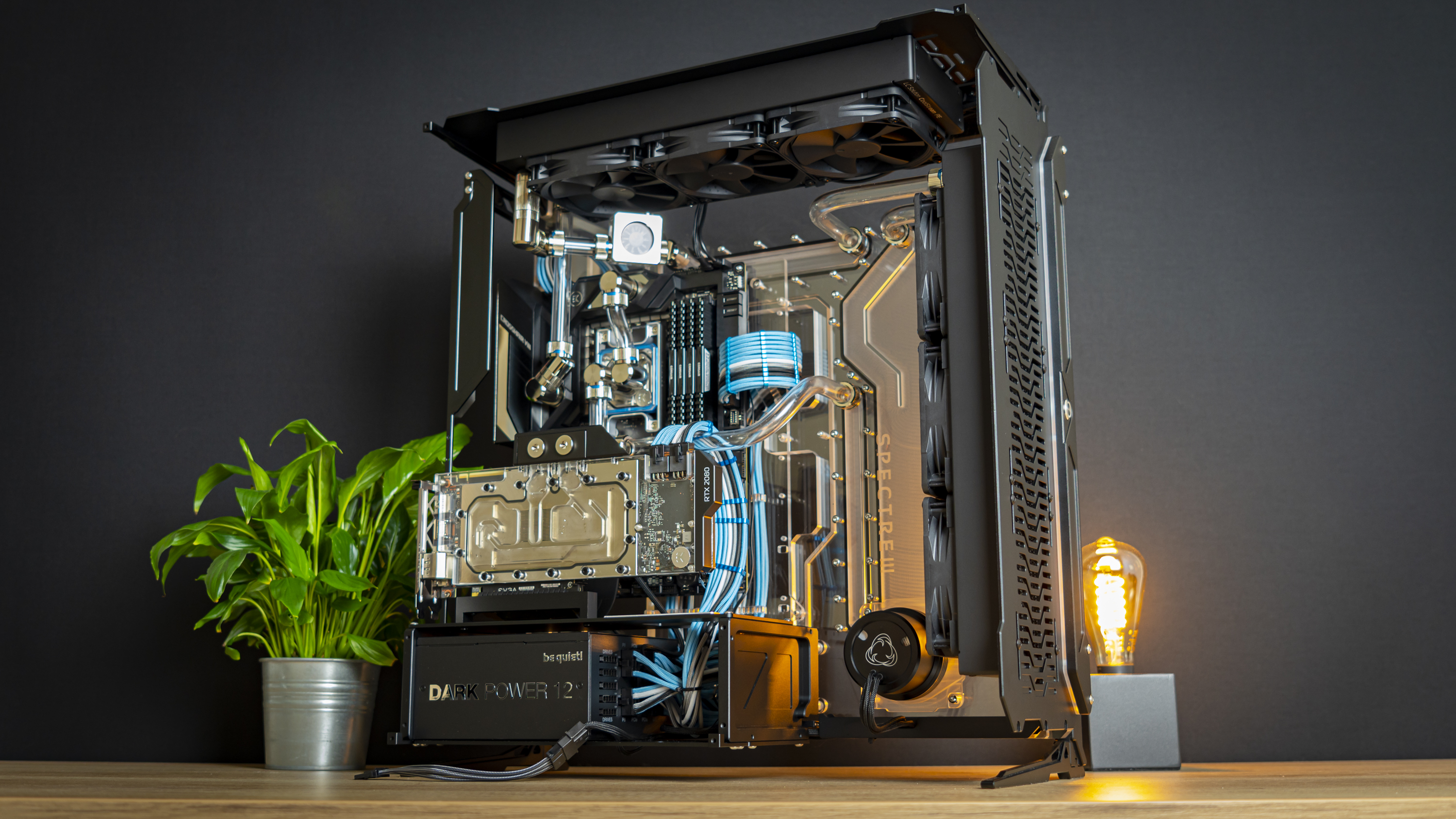
Up until now, we’ve come quite far in the assembly of Blue Shift. The case is built, and most of the components, including the cabling, is installed into the system. But there’s one job that still remains: building the cooling loop. And in terms of time and effort, this might be the biggest job yet.
Because this gives you only a few options for routing your loop, and I was bound to the motherboard, CPU block, GPU block and radiators that I had. I only roughly planned a loop beforehand. Of course, when the time to install the fittings and check my plans came, it didn’t work out quite as nicely as I had hoped.
So, I spent about four hours placing fittings, moving them around, moving the radiators and other bits around, until I was eventually happy with the rough loop layout I had created. Luckily, I had lots of fittings to play with, with tons of extension pieces, 90-degree angled fittings, 45-degree fittings and more. Having all these extra pieces can be crucial to making a loop work, as a 7mm extension piece, for example, can make the difference between having a very easy tube run and a difficult one. If you’re doing a cooling loop, do yourself a favor and buy more fittings than you think you need – you can often return the unused pieces.
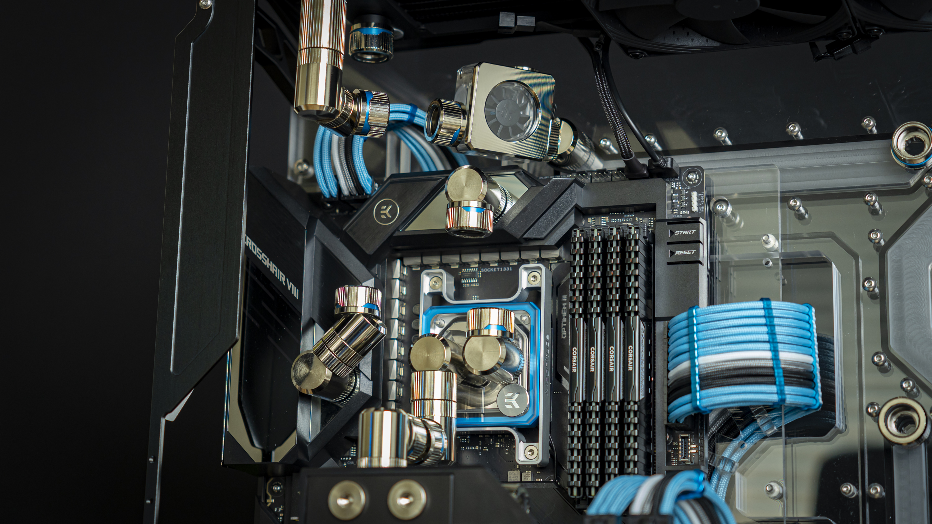
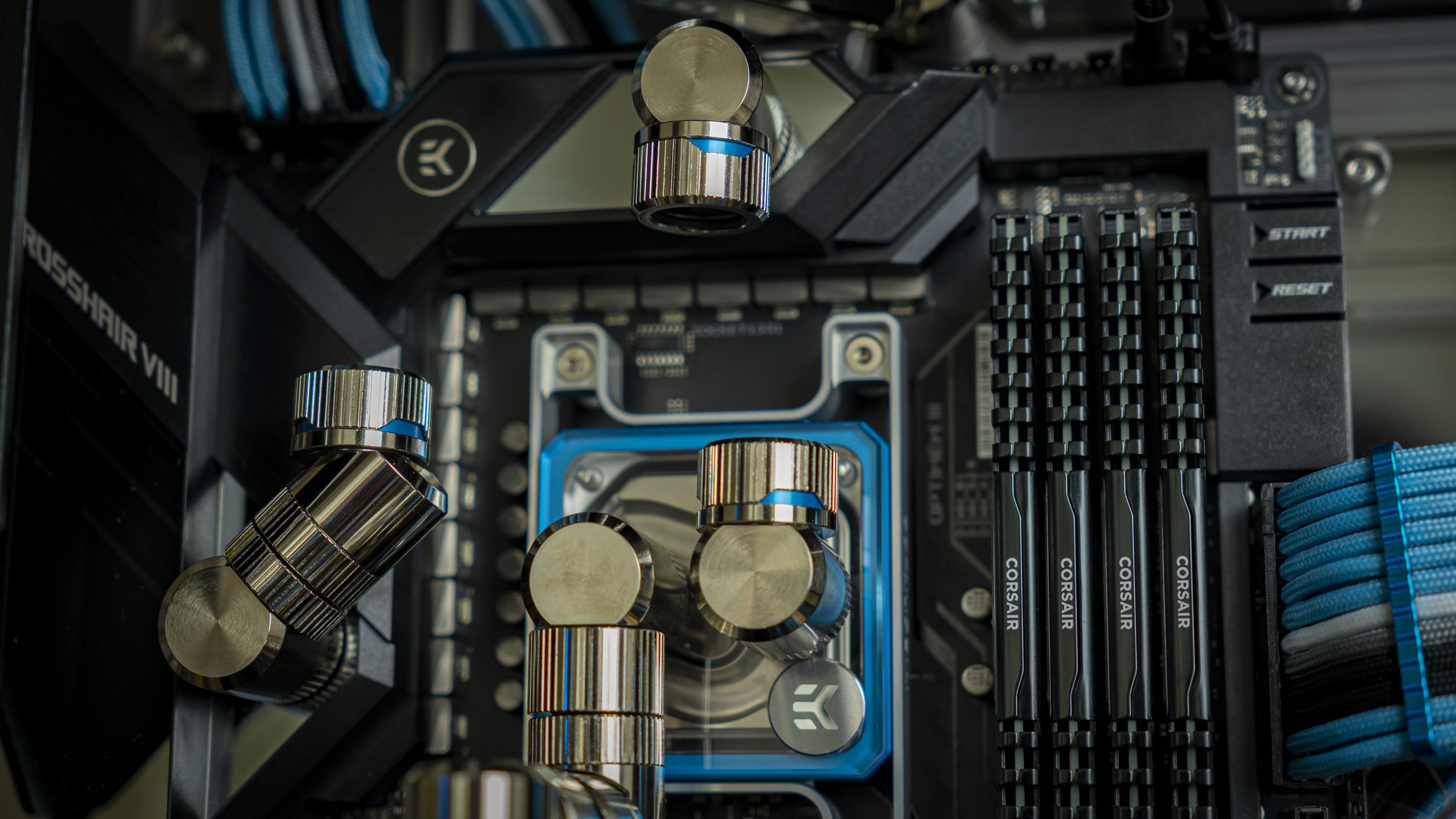
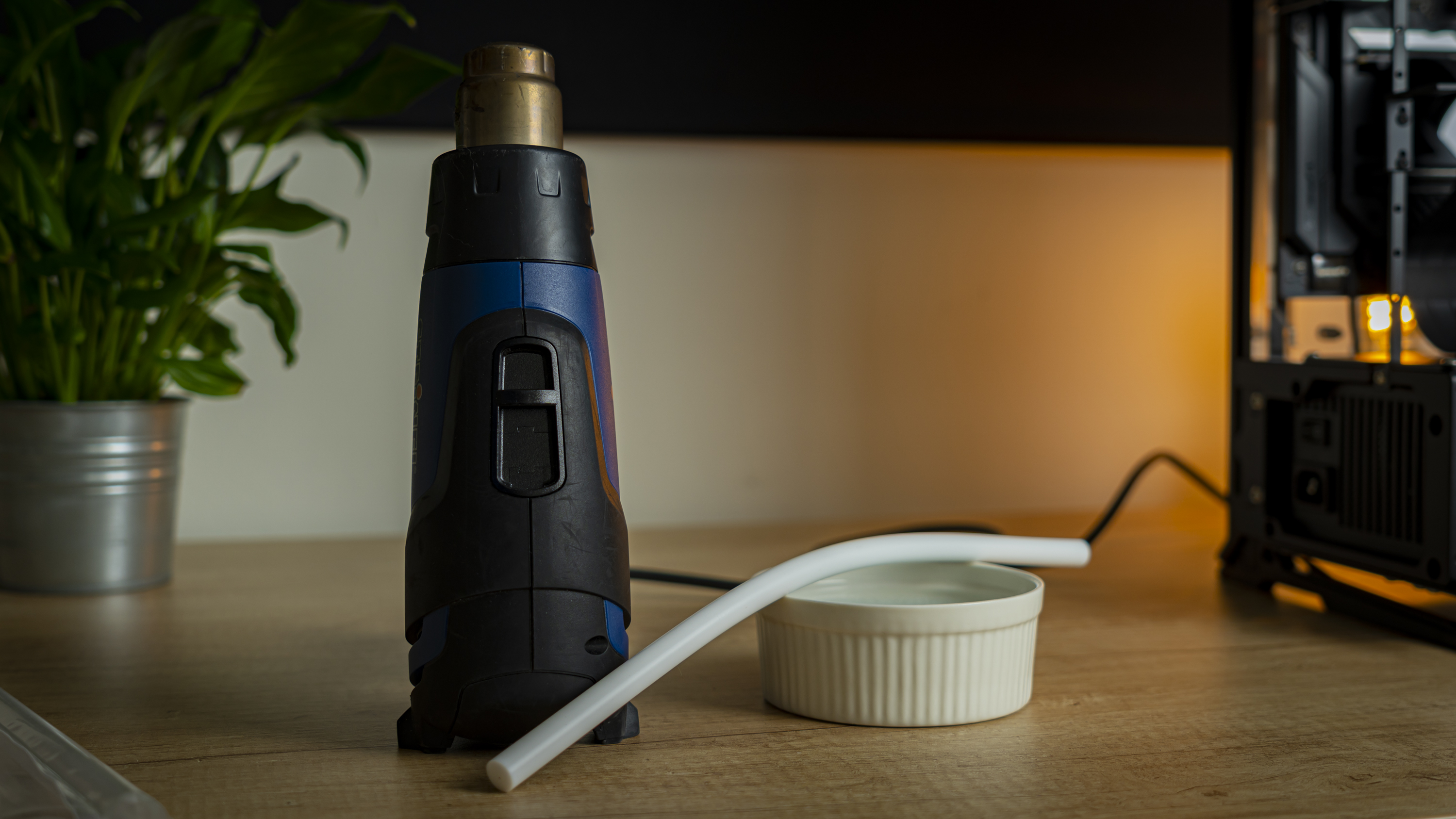
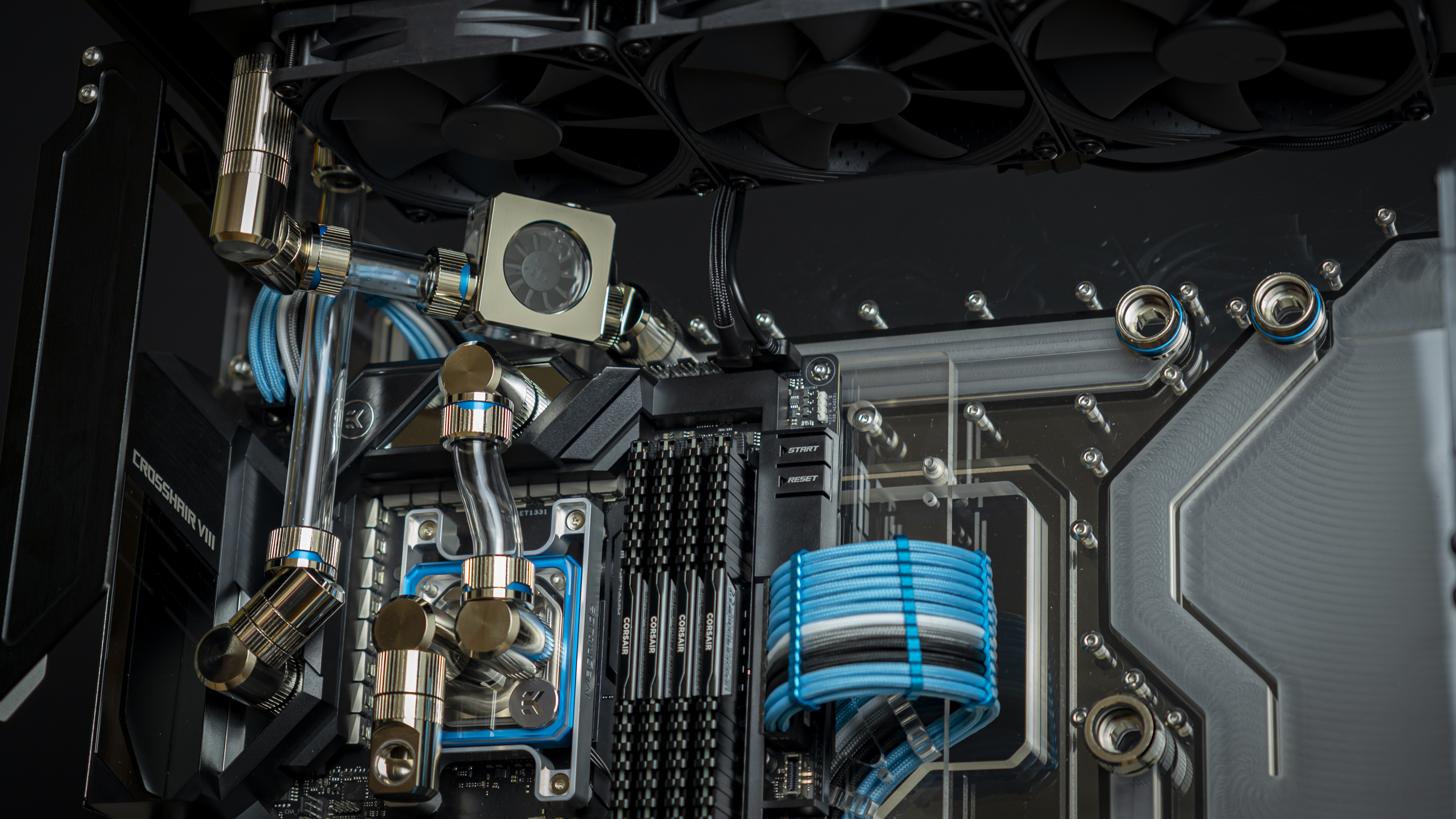
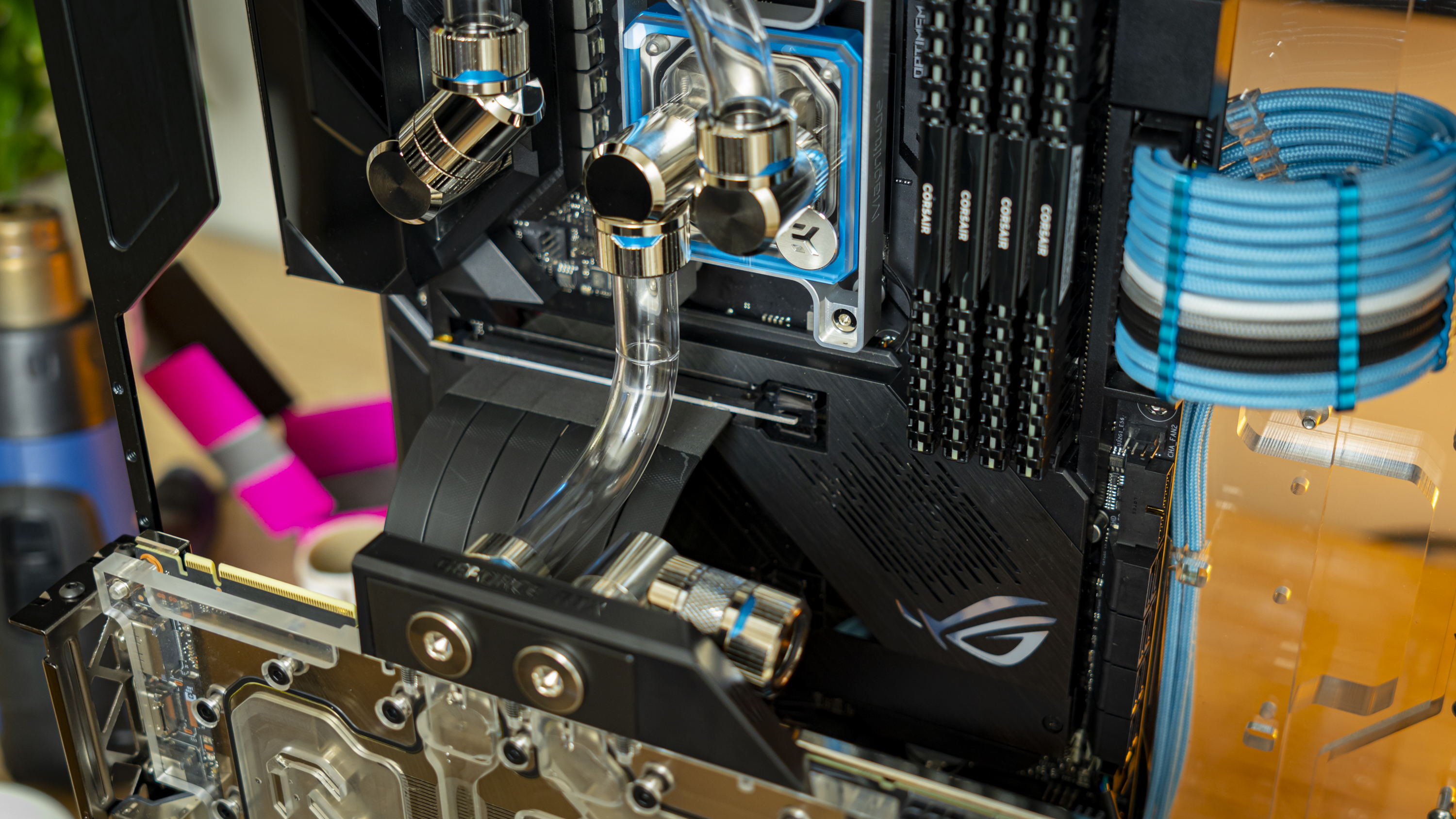
Pictured above is the layout I eventually settled on before tubing. Below I’ll take you through the details of each piece as I create and fit the bits of tubing for each spot, starting with the bend from the CPU block to the top of the VRM block. You can check out our recent feature on how to cut and bend hard tubing for details on how to do this right.
Tube Run 1: From CPU Block outlet to VRM block inlet
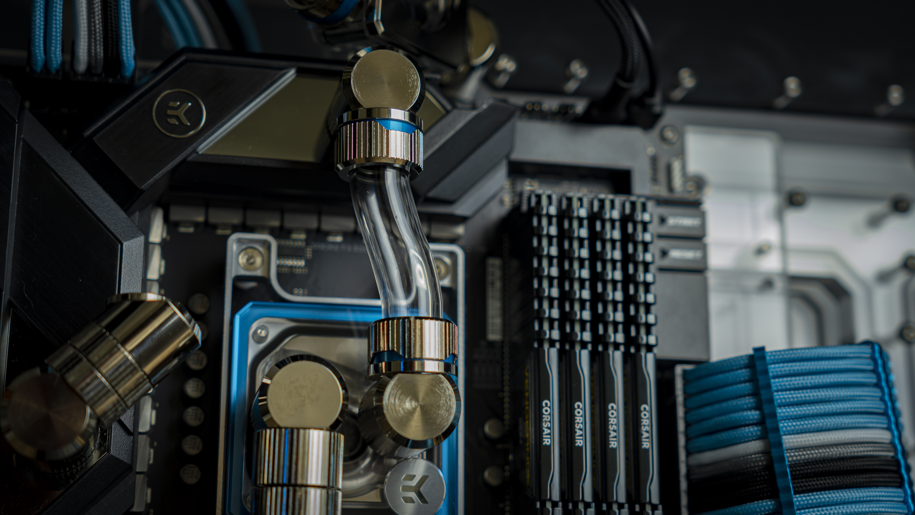
This is arguably the tubing run I struggled most with, and thus I decided to get it out of the way first as it required removing the CPU block. The two ports don’t line up very nicely, and no amount of extenders or angled fittings could help me, as they would over-correct or not look very nice.
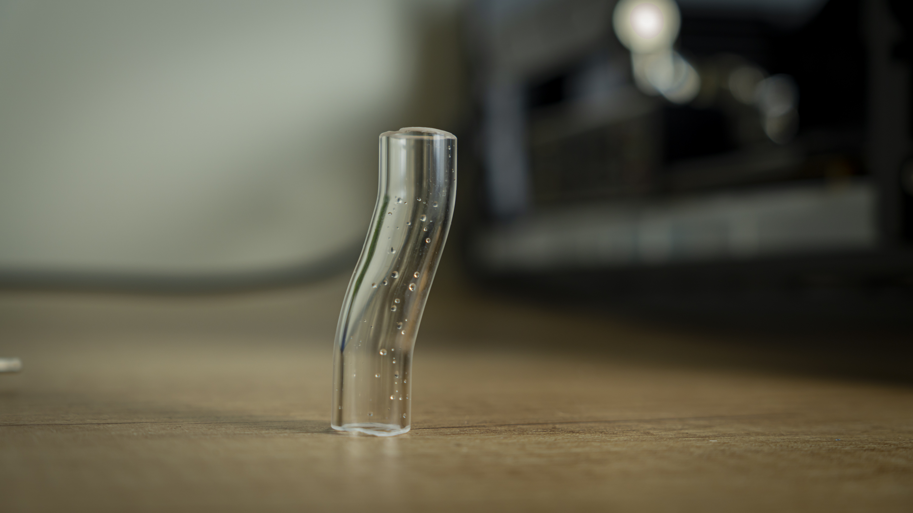
The distance between the two ports was big enough that a bent tube could work, but being pointed straight at each other, I would need to get the two fittings apart far enough to get the tube in. To do this, I first measured out the offset between the two ports, bent, cut, and chamfered the bit of tube, removed the GPU for better access, then removed the CPU block, put the bit of tube in place, and resecured the lot to create the connection.
Did I say before that you need to be willing to improvise and adapt along the way?
Get Tom's Hardware's best news and in-depth reviews, straight to your inbox.
Tube Run 2: From Radiator to Flow Indicator
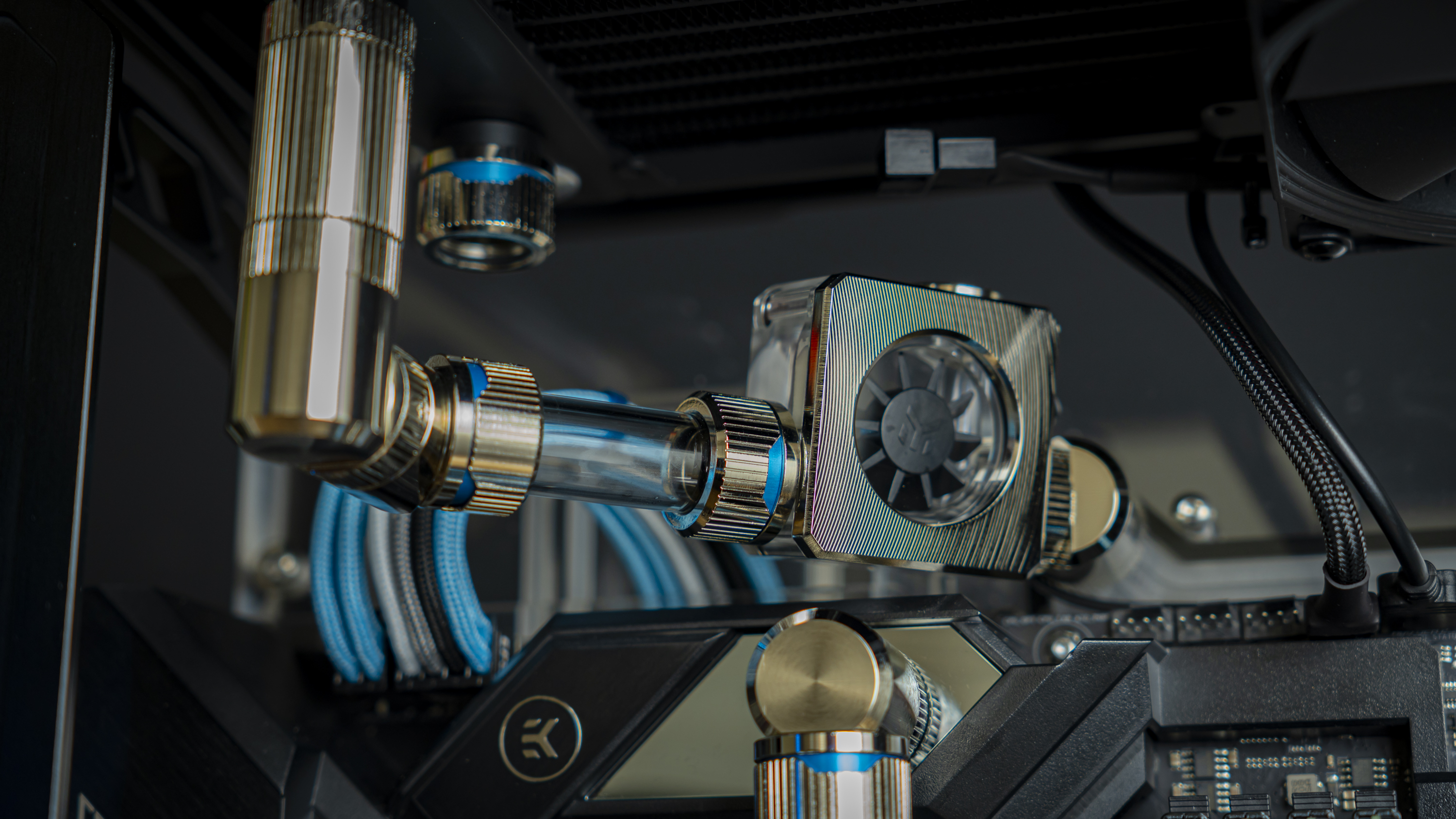
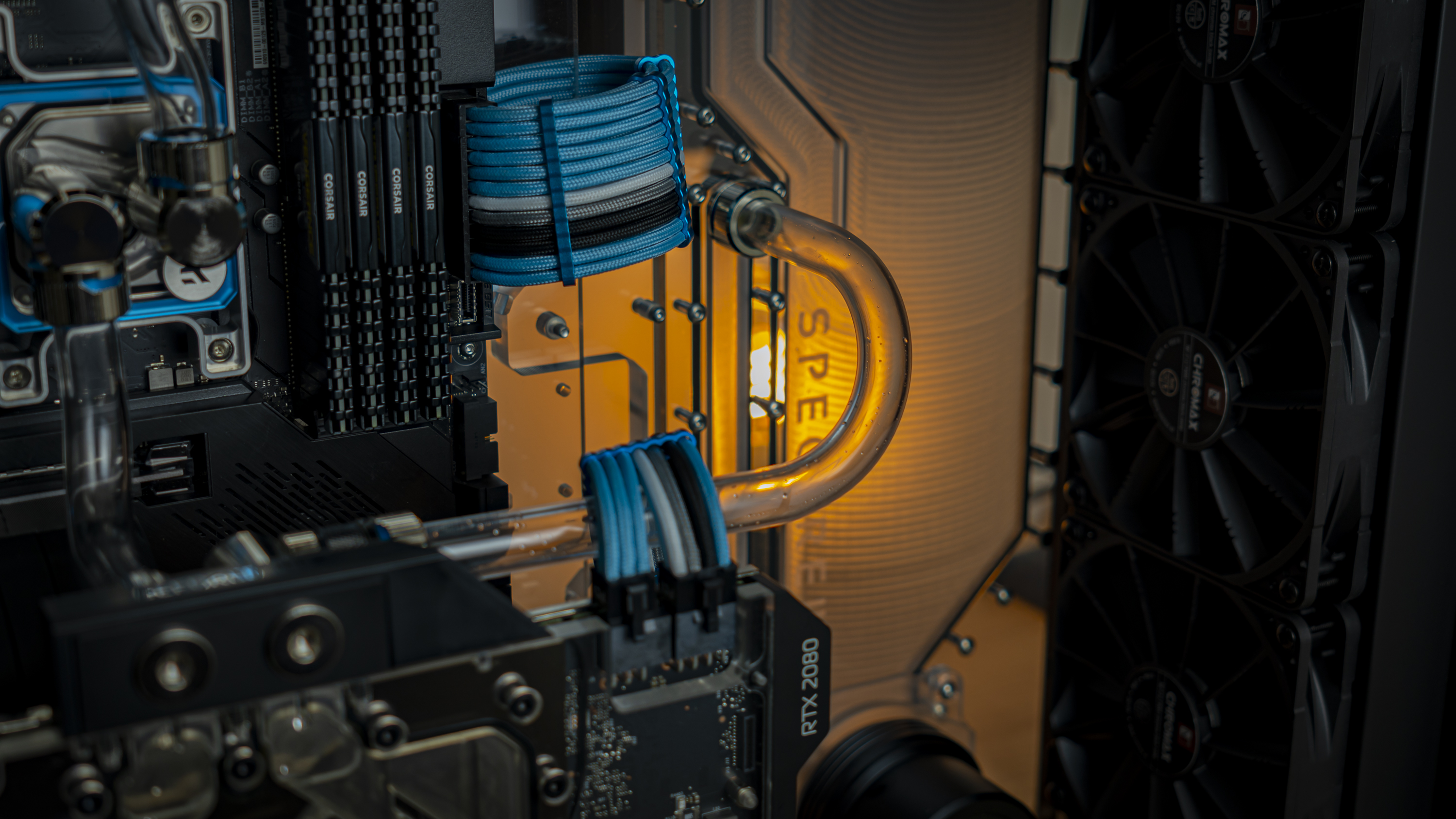
This tube run was very straightforward, with just a 5cm straight piece of tubing doing the trick. To get the fittings far apart enough to get the tube in though, I did loosen up the top radiator panel to get things apart enough for tube insertion. The lining up of these two ports wasn’t super-precise, but the fittings all have a little play, so it wasn’t a problem.
Tube Run 3: From VRM block Outlet to Radiator
This run was just as easy as the previous one, and the loose radiator panel came in handy – the straight bit of tube dropped right in. Again though, it didn’t line up very precisely, and if you look closely, you can see that the tube is angled slightly towards the motherboard near the top. But the difference is minimal and within the tolerances of the fittings’ play, and I was able to move the radiator a bit to minimize the offset.
A Quick Pressure Test
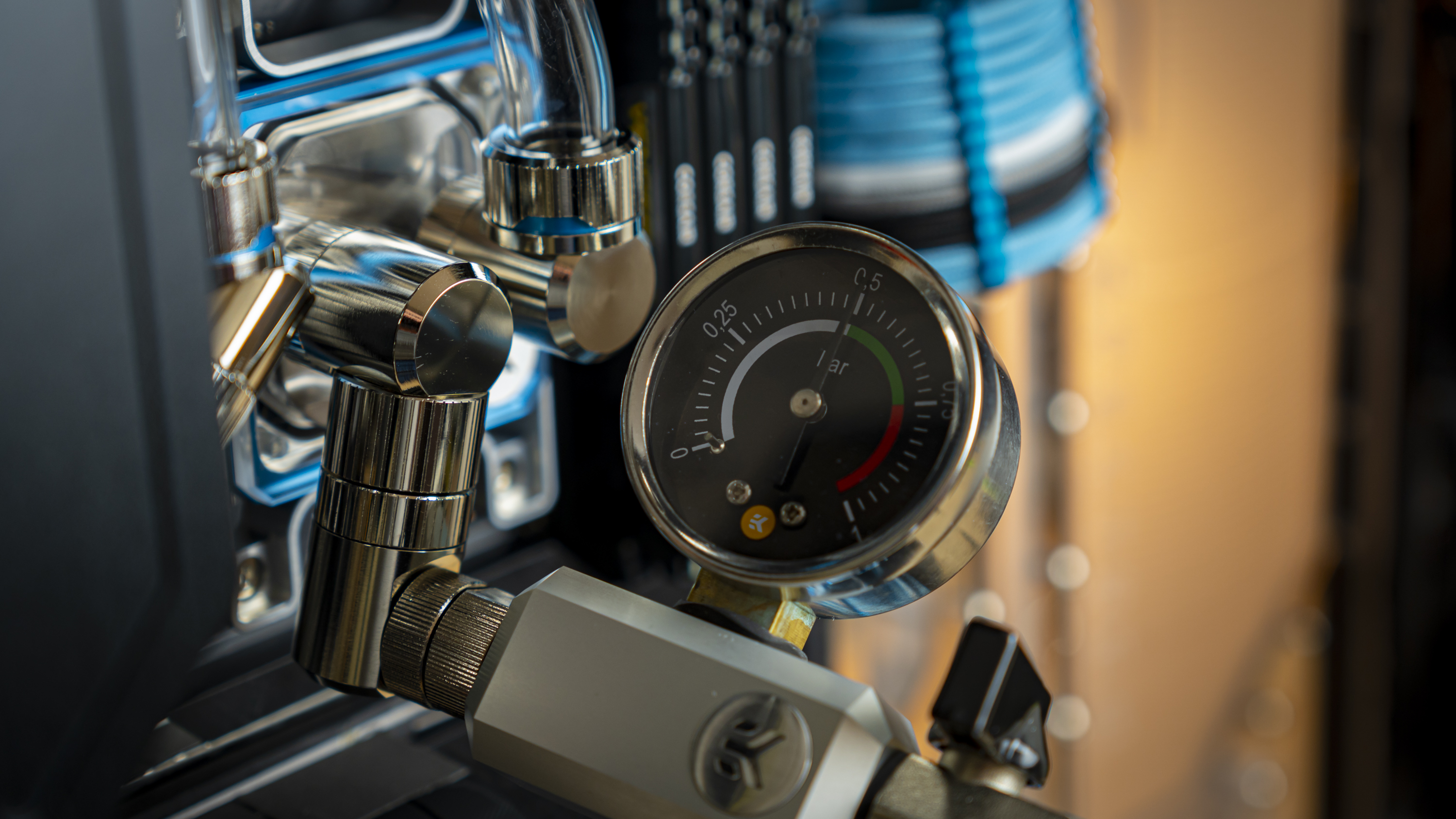
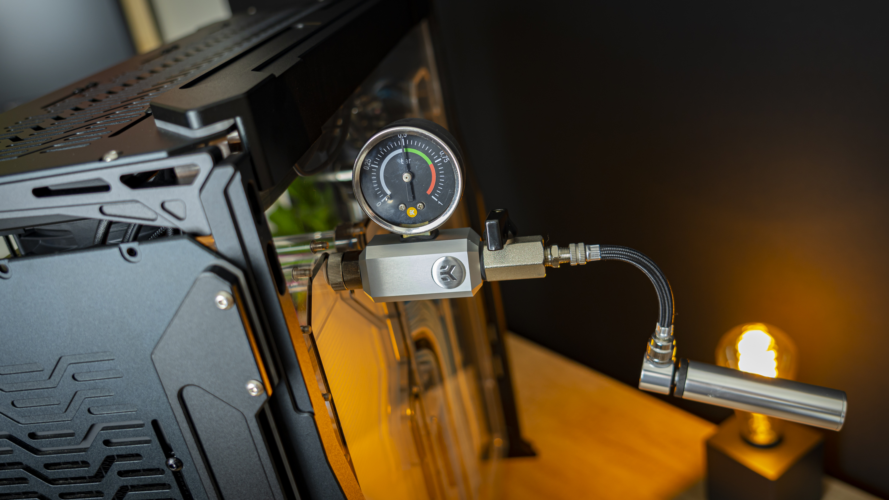
At this point, I plugged off one end of the distribution panel and installed the pressure tester on the CPU block to run a leak test. The loop may not be complete, but if I were to run into issues further down the line, I could then rule this area out from being the problem spot, possibly saving valuable diagnosis and re-assembly time.
Tube Runs 4 and 5: From Distribution Panel to Front Radiator
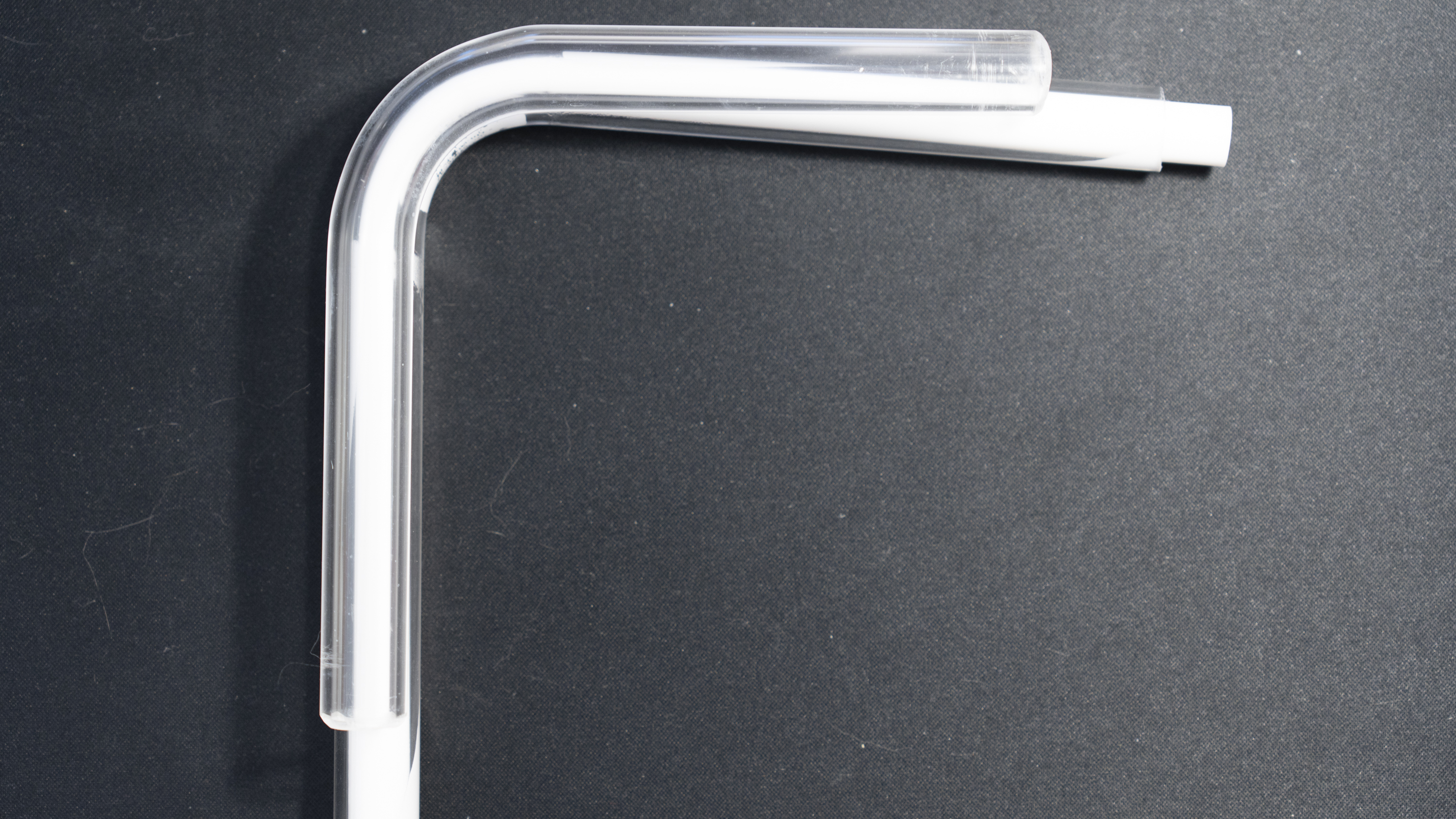
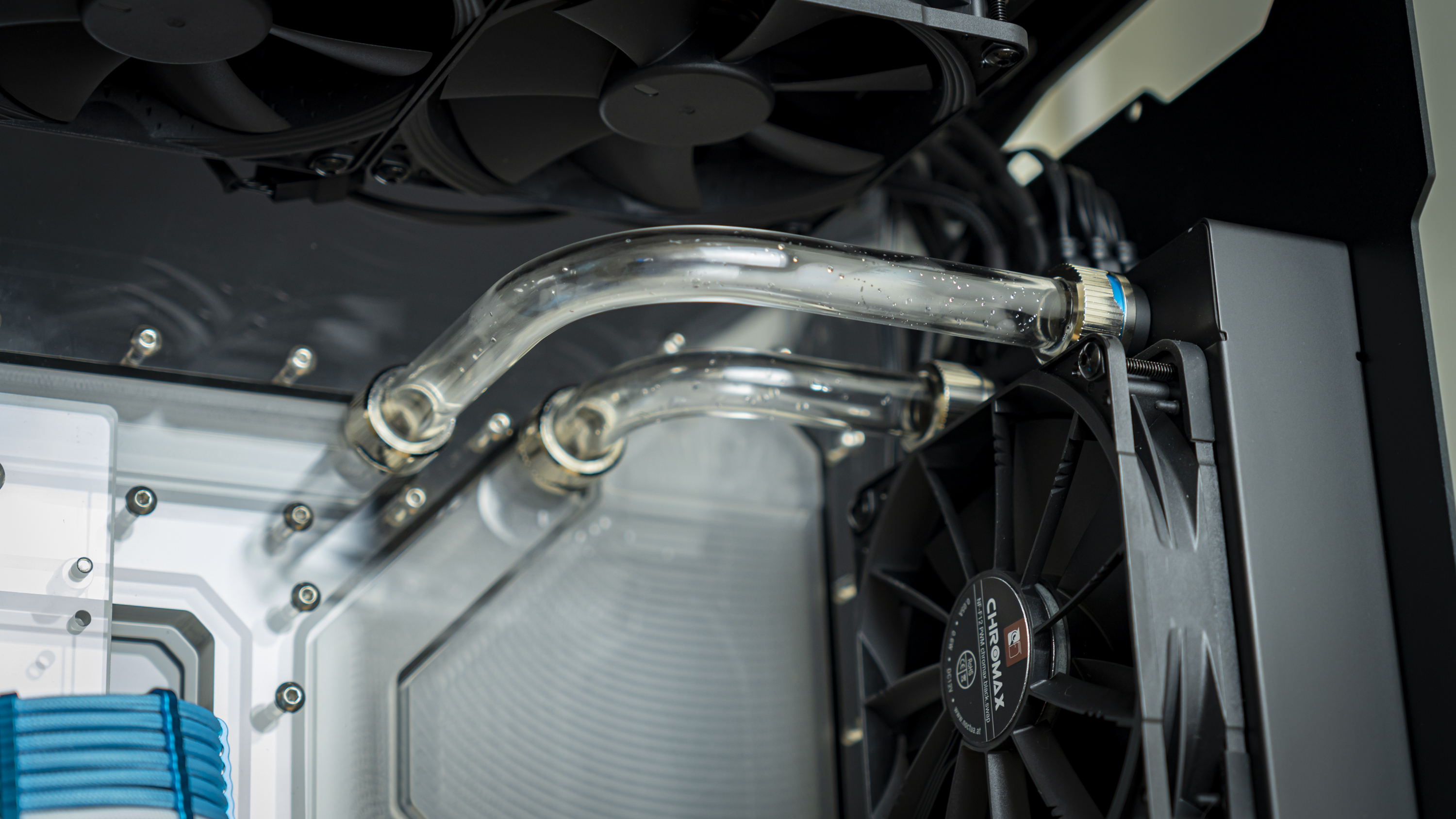
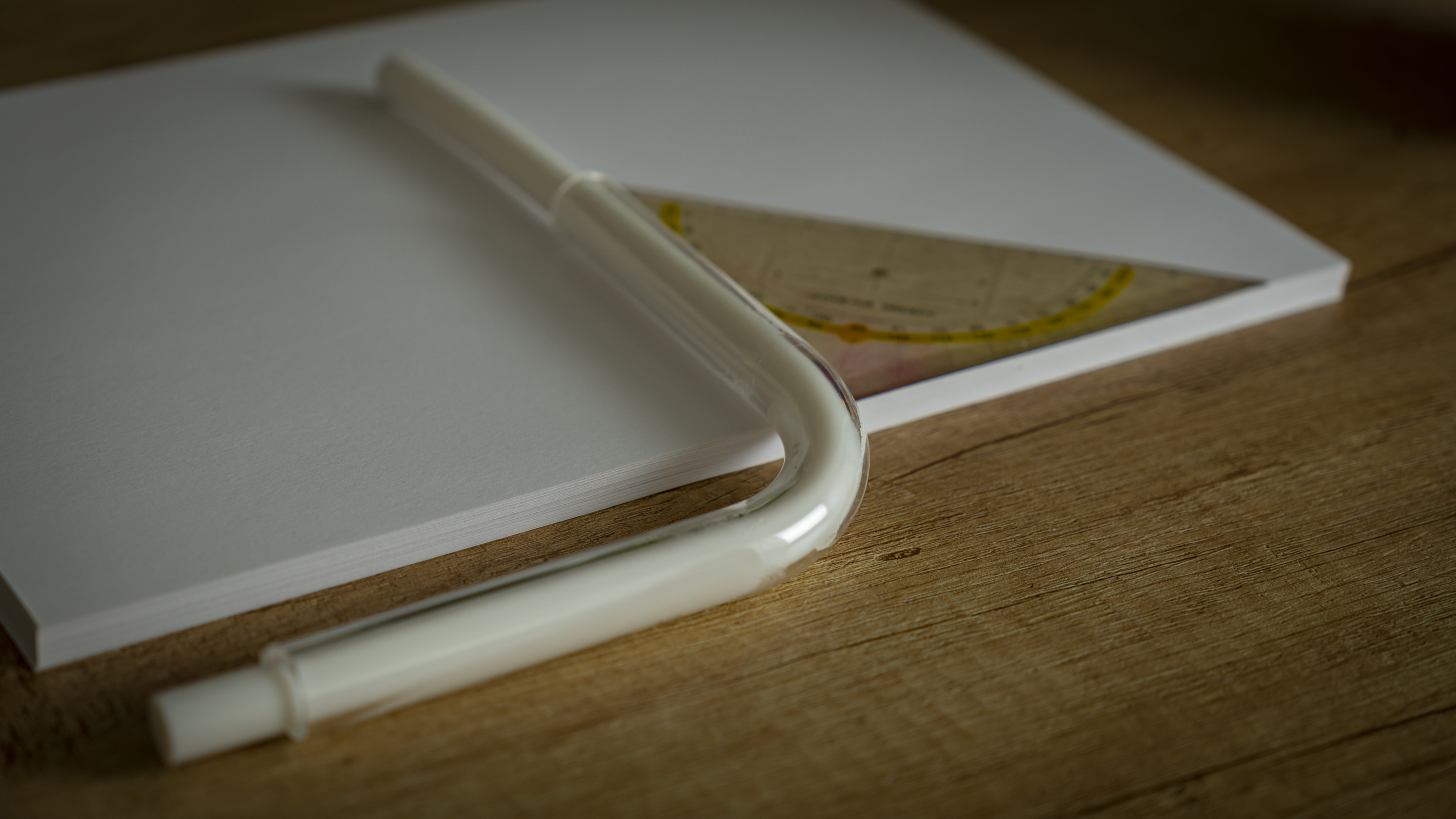
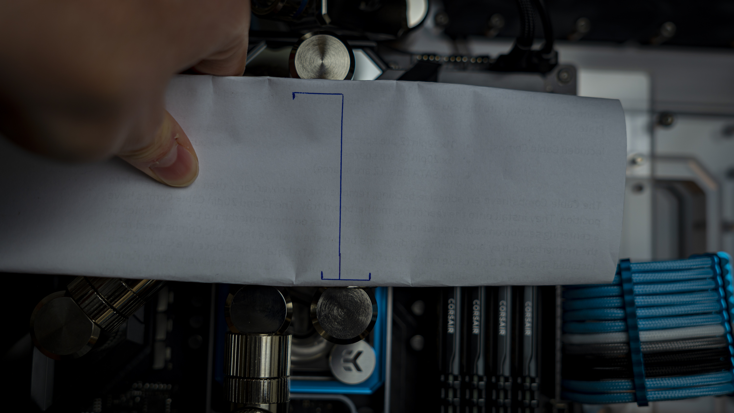
These two runs were at simple 90-degree angles, but this is where I was slightly unprepared. I hadn’t realized that my EKWB Modulus tool was only meant for 14mm tubes, so I had to eyeball the 90-degree angles. I used a piece of paper to eyeball the angle, and after a couple of pieces of wasted tube, I eventually got the hit right and they fit right in, of course with a loose front radiator panel to get the tubes in smoothly.
That being said, I did start tearing a few O-rings at this point. Puzzled as to why, I made sure to pay extra attention to how smoothly I chamfered the ends of my tubes. And I added a little extra dish soap to my soapy water for added lubrication when pushing the tubes past the O-rings into their fittings – and I think the latter made the biggest difference. The tubes suddenly needed a lot less force to press in once I added more soap.
Tube Run 6: From GPU Inlet to CPU Inlet
Because of the GPU block’s layout, I decided to run it in a reverse-flow direction for aesthetic reasons –the loop would simply get too complicated if I tried otherwise.
Although previously I aimed to use a whole bunch of fittings to achieve this connection because of a slight offset, at this point I was feeling confident, so I spared three 90-degree angles and a whole bunch of fittings, instead attempted a 90-degree bend with roughly a 7-8mm offset sideways, so that the fitting on the CPU block could be pointed straight down instead of at a slight angle. A stack of paper just as tall as the offset was perfect for achieving the right bend.
With the GPU block loose, the bit of tube slipped right into place in one go.
Tube Run 7: From Pump Outlet to GPU
This was the last run, and boy was I happy to have reached this far. I used the same strategy to bend it as I did the last tube, but then with a book and some paper to get to the 5.5 cm height offset in addition to the 90-degree bend. And again, to my surprise, 20 minutes later I had a tube that fit perfectly in one go.
For this run, I used a 90-degree angled fitting to point the GPU’s outlet in the right direction, onto which I fixed an Alphacool in-line fluid temperature sensor. This is because it’s best to run liquid cooling loops based on the fluid temperature rather than CPU temperature. And in this position, I would measure the coolant temperature straight from the reservoir, after it’s been cooled down by the radiators.
Drain Valve Install
I also dropped a compact drain valve at the other end of the distroplate, which will be helpful later when I need to drain the system.
Final Pressure Test Before Fill
I made it, at last. After a week of building (not including assembly of the case), the system was finally done and I could throw the pressure tester on. Of course, I don’t expect a perfect result in one go, but that doesn’t change the fact that my heart sunk a little when it wasn’t holding any pressure at all.
It couldn’t be, I thought. I’ve checked all the fittings throughout assembly, at worst it could leak a little slowly, but no pressure at all? Quickly I realized that although I’d mounted the pump, I wasn’t sure how tight it was supposed to be. I tightened it up a little more, and for a split second, the needle on the pressure tester would raise again, only to drop right back to zero when releasing the pump. This told me that I was at least on the right track, but I wasn’t going to tighten the pump up further in fear of cracking the acrylic.
So, I took off the pressure tester and laid the case on its backside again. I removed the pump, pulled out the gasket, lubricated it with some of my soapy water, and re-installed it. That seemed to have done it, and after tightening up the pressure tester a little further, the loop was holding pressure properly.
Can you imagine my relief? No, you can’t. It was immeasurable. Let’s fill the system up and test it.
Before moving to the next stage though, this section makes it all look like a breeze to work through – but I’m not showing you all the failed bits of tubing. As this is only the third watercooled PC I have ever built, I wasted quite a bit of tube. In the end, I needed seven 0.5-meter lengths of tube, most of which ended up in the wastebin. So if you don’t have a ton of experience, be sure to give yourself plenty of extra to work with.
Current page: Building the Cooling Loop
Prev Page Spectre III Assembly Next Page Filling, Testing and ConclusionNiels Broekhuijsen is a Contributing Writer for Tom's Hardware US. He reviews cases, water cooling and pc builds.
-
shunyata00 Love the color scheme. I designed that case for Singularity a few years back love seeing what people do with it. Very cool to see it on Tom's Hardware. Made my day.Reply
