PSU Repair: A Case Study
When your PSU won't start, most enthusiasts don't go beyond a paperclip or multimeter check. Today, we'll do a comprehensive repair of Antec's old SL300.
Preliminary Testing: PS_ON# Behavior
We already know that the supply has horrible deviations on the 5VSB output, so the next thing to look at would be correlation between the abnormal 5VSB output and turn-on failure.
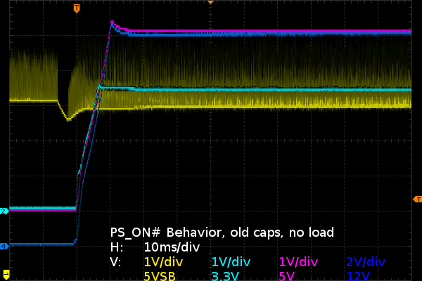
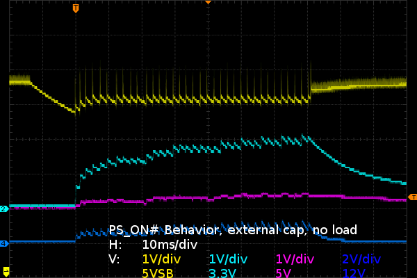
This first slide shows what happens at turn-on with the old 5VSB caps and no loading on 5VSB. The 5VSB output looks like junk throughout, but its DC value remains close to 5V and the main outputs look perfectly fine. While the overshoots aren't pretty, they are still within the 10% turn-on tolerance. In the remaining four slides, I added a 1200µF cap connected to the 5VSB pin on the ATX connector.
With the addition of that cap and no further changes, things go down the drain. Although the high-frequency content on the 5VSB line was greatly reduced, I now appear to have a problem with the 5VSB flyback operating irregularly, pulsing at about 500Hz. After 70ms though, the unit decides to shut down.
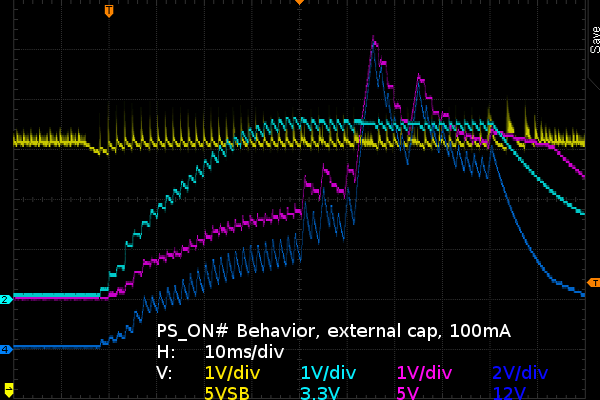
This time, I added the shunt voltage regulator from the previous page on the 5VSB output and adjusted the set-point voltage until I got 100mA through it before signaling PS_ON#. Now the flyback is pulsing at 600Hz and the main outputs are looking much livelier. They still shut down near the 82ms mark and do not look like anything you would want near your components.
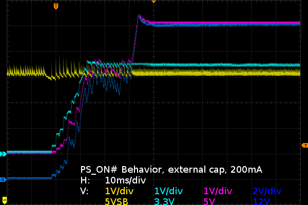
Dialing the load up to 200mA produces these traces and the first quasi-successful power-up: the 5VSB flyback is operating at 700Hz, the main rails manage to reach their respective nominal voltages and stay on. However, they do miserably fail the “smooth ramp” and 20ms maximum rise time requirements from Intel's 2013 PSU design guide. Results are also highly dependent on warm-up and cool-down times between runs.
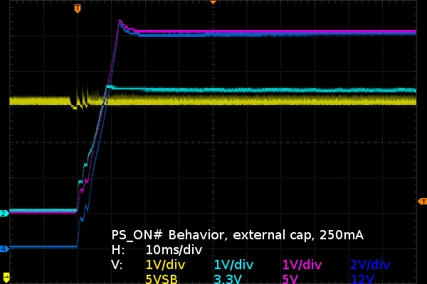
Stepping things up to 250mA starts looking good: the 5VSB flyback still has some minor hiccups just before main outputs come to life but it is now operating steady through the whole ramp, the main output ramps are much smoother and take just over 10ms.
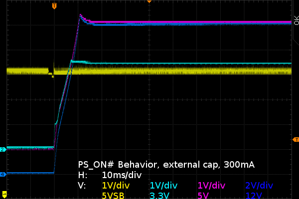
At 300mA of dummy loading, the main output ramps look as good as they are going to get.
Get Tom's Hardware's best news and in-depth reviews, straight to your inbox.
What do all of these waveforms have in common? They all show a dip on the 5VSB output just before the main outputs start coming to life, and during that dip, the 5VSB output behaves itself better than usual.
What preliminary conclusions can we draw from these observations? The strong correlation between how steady the 5VSB flyback is and how smooth the main output ramps are tells me the main switcher must either be bootstrapping from or entirely powered by an auxiliary output on the 5VSB flyback, and irregular flyback operation is preventing the main switcher from receiving steady enough power to operate normally. If I am correct about it, I should be able to loosen this dependency by putting a larger capacitor in the controller's power supply. If the controller's bootstrap happens to be tied into the 5VSB feedback circuit on the primary side, this could also explain the non-loaded voltage increase to 6V with either fresh caps or external caps. The main converter being powered by an auxiliary winding on the 5VSB supply would also explain the dip just before outputs start ramping up.
Current page: Preliminary Testing: PS_ON# Behavior
Prev Page Preliminary Testing: The 5VSB Rail Next Page Words Of Caution-
Nuckles_56 An interesting read, it was interesting following the process you used to troubleshoot the problemReply -
Crashman I used to do this for a living :)Reply
Don't tell my boss, I've managed to convince him that I'm only an expert at running benchmarks and writing about the results :) -
epsiloneri Disclaimers won't help. The people who will likely hurt themselves trying this are the same who lack the reading comprehension and self awareness to understand those disclaimers are directed at them. I admire you courage in publishing this.Reply
-
beetlejuicegr the truth is the paper clip and multimeter is all i can go in to psus. after all i haven't studied electricity or circuits or whatever.Reply
However i do hate to throw stuff earlier than it should, like you. -
C12Friedman I like this article and I fully agree with the conclusion. I've repaired a few PSU's but, for the most part I scavenge them anymore since I can't put them in a new system (nor would I want to) IMO they aren't really worth anything other than for on a test bench.Reply -
Mr A Daniel, I know next to nothing about electronics, and yet I could not stop reading this article. Fascinating! Thanks very much!Reply -
Urzu1000 This was a great article! It was informative, as well as interesting. Personally, I've only had one PSU fail on me so far. My brother-in-law's self-built computer had a really low-end Thermaltake PSU. 800W Bronze, and oh man, did that thing go out in a blaze of glory. Very loud popping, and smoke, and funny smells. When I ripped it out of the computer, there were burns inside the case. Miraculously, the other components remained unharmed, so I slapped in a new PSU (750W Gold Seasonic) and fired it up.Reply
Still working good, but I get black soot on my hands every time I open up that case. It's a black case, so it's hard to clean it off properly. -
Interesting article. I would have simply replaced the entire unit. You saw how to fix the failure, but how many units were damaged that you didn't see? A ticking time bomb that will eventually send some spike to your much more valuable hardware than a 10 year old PSU. Wasteful, yes. I get it. I don't like to waste either. And if it's on marginal hardware, fine. But on primary systems I'm not willing to take the risk. I'd rather throw away a 200$ part that has a 0.05$ repair solution, than risk frying 800$+ hardware.Reply
-
kalmquist "Antec's manufacturer (Channelwell in this case) got the live and neutral wires backwards, which means that in the “off” position, the neutral line gets opened and everything on the primary side becomes live instead of neutral."Reply
That's really bad--I doubt it is even legal to sell a power supply wired like that. I've never bought a CWT (Channelwell) power supply, and based on this I wouldn't buy one, except perhaps for a high end model where you might gamble that the company would exercise a bit more care.
