PSU Repair: A Case Study
When your PSU won't start, most enthusiasts don't go beyond a paperclip or multimeter check. Today, we'll do a comprehensive repair of Antec's old SL300.
Setup And Safety
In my LG repair, the power PCB was mounted a fair distance away from any surface, so I had no need to worry about possible insulation crushing. I was also only tapping into low voltage and relatively low-power signals, so I did not have to worry about insulation breakdown, electrocution or potentially very destructive shorts either. For this first and hopefully only set of test points I am going to need on the primary side, I will be tapping into circuits biased at somewhere in the neighborhood of -170V connected directly to mains through the input rectifiers, so a few extra precautions are warranted.
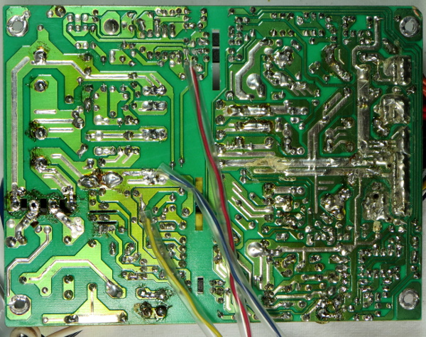
The first three points I want to look into are the 5VSB's auxiliary output, the 3844B's supply voltage and the bottom cap voltage, since I need to know what the other two I am interested in are referenced at. To tap into those signals, I used #24 wires and slipped plastic tubes on top of the sections that will end up under the PCB. This protects the wires' insulation from component pins and provides additional insulation in case the wire's insulation is dented or uneven.
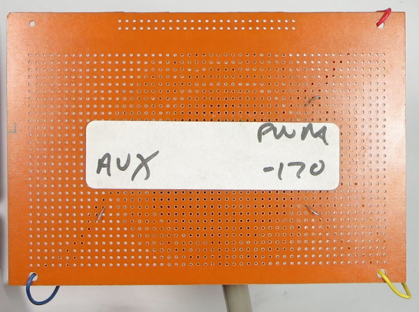
Another precaution is that instead of attaching probes directly to loose wires and just spreading them out a little, I used a perforated prototype board as a spacer to prevent accidental shorts or wandering. To protect my wires from the metal housing, I removed the fan, slipped a PVC tube over them and made them exit through the fan opening. This way, my three wires have a direct exit path across the PCB, under the transformers where there are very few component pins.
Get Tom's Hardware's best news and in-depth reviews, straight to your inbox.
-
Nuckles_56 An interesting read, it was interesting following the process you used to troubleshoot the problemReply -
Crashman I used to do this for a living :)Reply
Don't tell my boss, I've managed to convince him that I'm only an expert at running benchmarks and writing about the results :) -
epsiloneri Disclaimers won't help. The people who will likely hurt themselves trying this are the same who lack the reading comprehension and self awareness to understand those disclaimers are directed at them. I admire you courage in publishing this.Reply
-
beetlejuicegr the truth is the paper clip and multimeter is all i can go in to psus. after all i haven't studied electricity or circuits or whatever.Reply
However i do hate to throw stuff earlier than it should, like you. -
C12Friedman I like this article and I fully agree with the conclusion. I've repaired a few PSU's but, for the most part I scavenge them anymore since I can't put them in a new system (nor would I want to) IMO they aren't really worth anything other than for on a test bench.Reply -
Mr A Daniel, I know next to nothing about electronics, and yet I could not stop reading this article. Fascinating! Thanks very much!Reply -
Urzu1000 This was a great article! It was informative, as well as interesting. Personally, I've only had one PSU fail on me so far. My brother-in-law's self-built computer had a really low-end Thermaltake PSU. 800W Bronze, and oh man, did that thing go out in a blaze of glory. Very loud popping, and smoke, and funny smells. When I ripped it out of the computer, there were burns inside the case. Miraculously, the other components remained unharmed, so I slapped in a new PSU (750W Gold Seasonic) and fired it up.Reply
Still working good, but I get black soot on my hands every time I open up that case. It's a black case, so it's hard to clean it off properly. -
Interesting article. I would have simply replaced the entire unit. You saw how to fix the failure, but how many units were damaged that you didn't see? A ticking time bomb that will eventually send some spike to your much more valuable hardware than a 10 year old PSU. Wasteful, yes. I get it. I don't like to waste either. And if it's on marginal hardware, fine. But on primary systems I'm not willing to take the risk. I'd rather throw away a 200$ part that has a 0.05$ repair solution, than risk frying 800$+ hardware.Reply
-
kalmquist "Antec's manufacturer (Channelwell in this case) got the live and neutral wires backwards, which means that in the “off” position, the neutral line gets opened and everything on the primary side becomes live instead of neutral."Reply
That's really bad--I doubt it is even legal to sell a power supply wired like that. I've never bought a CWT (Channelwell) power supply, and based on this I wouldn't buy one, except perhaps for a high end model where you might gamble that the company would exercise a bit more care.

